You are using an out of date browser. It may not display this or other websites correctly.
You should upgrade or use an alternative browser.
You should upgrade or use an alternative browser.
ANH Motorised stunt Saber experiments (& blades) Part 1
- Thread starter Mouse Vader
- Start date
Mouse Vader
Sr Member
Not posted lately as I've been busy doing stuff (inc on this project) & thinking.
I've been thinking on the Info Jon has provided & In particular about his sketch. As is stands I there appears to be no way to change the blade without a fairly major strip down & I've been trying to figure out how to make this work.
This is what my fevered little brain has come up with. It doesn't work for the the Kanobi stunts but does as a general arrangement for both the graffy & vader ones & offers explanations for at least three things that have been puzzles for me upto now. It's not a finished 'theory' or anything like that - for instance it doesn't deal with the collars we see - but I think it is quite indicative the general principal.
The ingredient not on the sketch but is in the conservation is the push fitting of the bearing. If this is literally just that - push in with the fingers - & retained with the infamous grub screw we see on the graffy, then by slackening the grub screw the whole innards can be withdrawn from the front by pulling on the blade - the motor/gearbox being a friction fit from the paper wedges. The blade grub screw can now be loosened, blade swapped & it all pushed back in.
There is a flaw in this arrangement, one that I think proved 'fatal' & supports this reasoning & that is relies on a good friction fit of some folded up paper.
What this arrangement solves for me is:
1. The purpose of that grub screw on the graffy (& yes Kurtyboy I know you used it for just that purpose on yours). This was my first impression of it but thought it lead to misalignment of bearing & motor - I've mod'ed the MK2 to this & it's not a problem.
2. It gives a method for changing the blade on the vader stunt as the blade goes deep in to the shroud so there would be no access to a grub screwed collar.

It was this that lead me to think of the tube drive shaft & just stuffing a blade down the hole for a friction fit.
3. It explains what the f--k Dave P is doing in some parts of the duel. When I first saw the film in 1977 I notice DV was holding his saber in a very peculiar manner sometimes - like he was trying to hide it. What I have recently found is Dave P is actually holding the blade in front of the shroud, you can see light reflecting from the blade below his upper hand in this screen shot -

and his hand in front the shroud & on the blade in these three.


Why's he doing that? I think this is the fatal flaw of relying on paper wedges to hold things in place. The innards have come loose & he's holding all the works in. I've not been able to see any grub screw on this saber but we have so few shots of it in ANH guise it could just not be showing up. Anyhow that's the only explanation I've got (or heard of) to explain why he's doing what he's doing.
From post # 196 pg 10

 www.therpf.com
Jon informs us that there were about eight (yes that's 8) mechanised sabers for ANH. (I'm going 2 graffies - the hut/falcon & shared Luke/Vader & 3 each for the duel).
So for them to stop using the vader stunt (& or graffies) there has to be a systemic fault & not just single mishaps. My hunch is that this is what I describe above. The Kanobi/V2 can't be made to work with that system so was immune.
I've already mod'ed the MK2 to push/slip fit & grub screw for the single bearing & even if I remove the motor retaining screw there is still enough friction to prevent the motor rotating in the core sleeve & it's a slip fit currently. It's a viable set up.
Pic's & some other tweeks to follow.
I've been thinking on the Info Jon has provided & In particular about his sketch. As is stands I there appears to be no way to change the blade without a fairly major strip down & I've been trying to figure out how to make this work.
This is what my fevered little brain has come up with. It doesn't work for the the Kanobi stunts but does as a general arrangement for both the graffy & vader ones & offers explanations for at least three things that have been puzzles for me upto now. It's not a finished 'theory' or anything like that - for instance it doesn't deal with the collars we see - but I think it is quite indicative the general principal.
The ingredient not on the sketch but is in the conservation is the push fitting of the bearing. If this is literally just that - push in with the fingers - & retained with the infamous grub screw we see on the graffy, then by slackening the grub screw the whole innards can be withdrawn from the front by pulling on the blade - the motor/gearbox being a friction fit from the paper wedges. The blade grub screw can now be loosened, blade swapped & it all pushed back in.
There is a flaw in this arrangement, one that I think proved 'fatal' & supports this reasoning & that is relies on a good friction fit of some folded up paper.
What this arrangement solves for me is:
1. The purpose of that grub screw on the graffy (& yes Kurtyboy I know you used it for just that purpose on yours). This was my first impression of it but thought it lead to misalignment of bearing & motor - I've mod'ed the MK2 to this & it's not a problem.
2. It gives a method for changing the blade on the vader stunt as the blade goes deep in to the shroud so there would be no access to a grub screwed collar.
It was this that lead me to think of the tube drive shaft & just stuffing a blade down the hole for a friction fit.
3. It explains what the f--k Dave P is doing in some parts of the duel. When I first saw the film in 1977 I notice DV was holding his saber in a very peculiar manner sometimes - like he was trying to hide it. What I have recently found is Dave P is actually holding the blade in front of the shroud, you can see light reflecting from the blade below his upper hand in this screen shot -
and his hand in front the shroud & on the blade in these three.
Why's he doing that? I think this is the fatal flaw of relying on paper wedges to hold things in place. The innards have come loose & he's holding all the works in. I've not been able to see any grub screw on this saber but we have so few shots of it in ANH guise it could just not be showing up. Anyhow that's the only explanation I've got (or heard of) to explain why he's doing what he's doing.
From post # 196 pg 10
Halliwax's weird V3 theory
2021 Update I originally started this thread back in 2018, its main goal was to prove that some photos which we thought at the time was the v2 was actually the v3. Years have gone by, with new discoveries being made almost every month. There is a lot of new data, discoveries and photos that...
www.therpf.com
Jon informs us that there were about eight (yes that's 8) mechanised sabers for ANH. (I'm going 2 graffies - the hut/falcon & shared Luke/Vader & 3 each for the duel).
So for them to stop using the vader stunt (& or graffies) there has to be a systemic fault & not just single mishaps. My hunch is that this is what I describe above. The Kanobi/V2 can't be made to work with that system so was immune.
I've already mod'ed the MK2 to push/slip fit & grub screw for the single bearing & even if I remove the motor retaining screw there is still enough friction to prevent the motor rotating in the core sleeve & it's a slip fit currently. It's a viable set up.
Pic's & some other tweeks to follow.
Mouse Vader
Sr Member
I've redone my battery pack & wiring with some new single core wire. Works well but I have a suspicion the remaining fault I was getting is maybe with the switch. [edit 4.7.19. I have not found any other faults since, switch seems Ok.]

& made a second set with more convenient speed controller. Also put tails on a couple more motors inc the 900rpm.

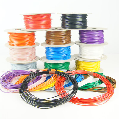
I really like this new wire. It's nice to work with & when twisted together looks just like what we see in the hut pictures. My only criticism is that it maybe just a tad thin though it's looking OK in my photo's. If I have to reorder I think I might go for the next size up at 11amp rating. This is the 7amp rated.
( single core stranded cable / wire. PVC coated.)

This is the 900 in the MK2 at full whack on the speed controller then dropping V's.
I'm finding it hard to do a frame count to gauge the rpm as over a certain level it all looks the same. I'll check the volts later & try to get some calibration. For the time being it's shows that this set up can handle relatively high rpm with no trouble & that the 900 motor also has no problems with the this sort of load.
This shows the MK2's new bearing set up & how the grub screw keeps things in place well enough - for now. I have found that if I tighten the grub screw 'fully' it interferes with the bearing, causing drag on the inner ring so it sometimes stops. I'm only lightly pinching the bearing in this video but it's keeping everything put.
This shows how the motor stays put in the core when running even though it's a very light slip fit. You can just see it twitch when I switch on & off, a bit tighter fit & this would be fine. I'm thinking the switch would act as stop to prevent over insertion.
More bits on the way for MK3 with tube drive shaft.
& made a second set with more convenient speed controller. Also put tails on a couple more motors inc the 900rpm.
I really like this new wire. It's nice to work with & when twisted together looks just like what we see in the hut pictures. My only criticism is that it maybe just a tad thin though it's looking OK in my photo's. If I have to reorder I think I might go for the next size up at 11amp rating. This is the 7amp rated.
( single core stranded cable / wire. PVC coated.)
Single Core Stranded 12V 24V Cable Thin Wall Wire All AMP Ratings 11 Colours | eBay UK
Thin Wall Single Core Stranded 100% Copper Cable. Plain Copper Conductors to BS EN 60228:2005 - PVC Insulated. Suitable for use at temperatures from -40°C to 105°C with excursions up to 120°C. 10M Coiled.
www.ebay.co.uk
This is the 900 in the MK2 at full whack on the speed controller then dropping V's.
I'm finding it hard to do a frame count to gauge the rpm as over a certain level it all looks the same. I'll check the volts later & try to get some calibration. For the time being it's shows that this set up can handle relatively high rpm with no trouble & that the 900 motor also has no problems with the this sort of load.
This shows the MK2's new bearing set up & how the grub screw keeps things in place well enough - for now. I have found that if I tighten the grub screw 'fully' it interferes with the bearing, causing drag on the inner ring so it sometimes stops. I'm only lightly pinching the bearing in this video but it's keeping everything put.
This shows how the motor stays put in the core when running even though it's a very light slip fit. You can just see it twitch when I switch on & off, a bit tighter fit & this would be fine. I'm thinking the switch would act as stop to prevent over insertion.
More bits on the way for MK3 with tube drive shaft.
Last edited:
Mouse Vader
Sr Member
I wondered if /when I'd get asked this & it's a very awkward one for me to answer. Interested ? Yes - able to fulfill ? probably not. My personal circumstances leaves me very little time for this sort of thing & to do what I have so far has been far from easy - or rather has impacted on other things that it really shouldn't have. Also it was never my intention to do 'production runs'. I wanted one or two for myself & to conduct the blade tests with & I thought I'd post that process as a thread so others could use that info to build their own or tweak for limited runs.
I may be able to do one or two at a (much?) later date if folk are prepared to wait, esp if it's not a full build but I really need to see how long it takes to do one start to finish before I can say for certain or come up with a price for that matter.
I mentioned earlier I was thinking of doing a Vader & also motorising my Solo's Hold V2, This has now become a full blown must , which is annoying.
I'm close to finalising my pattern for these cores or rather patterns the main dif being what type of bearing & with or without the motor retention screw. With - means the whole core will slide out the front for access to the workings by removing the buttons, without - means a grub screwed front bearing & push fit motor to slide out for access with the core 'sleeve' still retained in the outer tube. The latter being about as close to the genuine article as I think I'll be able to do. Drive shaft type will depend on blade type & how they attach.
The 646rpm motor arrived this morning & looks good. The motor part is nearly twice as long as the others so must surely have more grunt. Gave it a quick spin holding connectors to the terminals (6V regulated battery pack) & it sounds sweet.
I've also tried one of my 400rpm motors on 3 fully charged lipos (11.7V) with no discernible problems & it was certainly well over 600rpm maybe even over 720 which is good news as they're about 1/2 the price of 646 & I already have 3. I'll try & get some pic's up of the newbie later.
Mouse Vader
Sr Member
KB - can't find any info on the frame rate on your video's as on YouTube. I didn't know it could be changed on MP4 - my info came from a web search to find MP4 frame rate & this tallied with the info on my digiSLR.
Is there any way I can find out what frame rate a particular YouTube video is running?
I defo was encountering a repeat frame 4 to 5 on several of the BTS StarWars video's as other moving objects in the same view also remained static.
I encoded my 4K clips at 24FPS so maybe YouTube preserves the frame rate?
Kurtyboy - finally got some info on your video format. It downloaded as a Google/On2's VP9 Video (VP90) with frame rate at 23.97 fps. so it has preserved what you encoded. What was the original format you coded from?
Mouse Vader
Sr Member
Managed get some calibration done on motor rpm. Had to do about a dozen short videos to analyse (don't worry I'm not posting them all). I discovered the 900 isn't 900 at 6V it's actually 720 rpm which is one of the speeds I was aiming for. It gives 600 at 5V.
I've been digging about on the interweb for data on these JGA25-310 motors hoping to find what rpm the actual motor part does but could only find out they're rated 3-12v (or 6-12v another site) so I'm fine running 12V on them. I've found the 400 does 600rpm at 9.75V and gives 720rpm at 11.5V. The longer JGA25-370 (on the 646) is rated 6-18V and has the same gearbox set up of 9.64:1 as found on the 400, so looks to be a higher revving (more powerful ?) motor.
Check the sound now on the MK1b single bearing setup at 600rpm compared to the vid clip.
posted again for convenience.
I also found more on how movie frame rate is transposed to video (NTSC 30fps = MP4). still trying to fully transpose that to what I see in dif. video clips.
Does explain the double images I see on some of them.

 en.wikipedia.org
I've been digging about on the interweb for data on these JGA25-310 motors hoping to find what rpm the actual motor part does but could only find out they're rated 3-12v (or 6-12v another site) so I'm fine running 12V on them. I've found the 400 does 600rpm at 9.75V and gives 720rpm at 11.5V. The longer JGA25-370 (on the 646) is rated 6-18V and has the same gearbox set up of 9.64:1 as found on the 400, so looks to be a higher revving (more powerful ?) motor.
Check the sound now on the MK1b single bearing setup at 600rpm compared to the vid clip.
posted again for convenience.
I also found more on how movie frame rate is transposed to video (NTSC 30fps = MP4). still trying to fully transpose that to what I see in dif. video clips.
Does explain the double images I see on some of them.
Three-two pull down - Wikipedia
Mouse Vader
Sr Member
Pedants amongst you may have noticed I'm fudging 600rpm slightly (easier to frame count) by using 2 turns in 5 frames & 25 FPS (this turns out to be PAL video standard ). Movie standard is of course 24 FPS. If we use the latter then RPM works out at 576 for the actual movie.
In my RPM tests I got the 400 motor clocked at 578 RPM on 9.5V. I can't tell the difference in the above test.
I think audio is not affected by frame rate conversion as on film this is recorded as continuous data (a bit like a bar code) on the edge of the film so all that's required would be to re-record this in sinc. to the video file.
Just thought I clear that up.
Mouse Vader
Sr Member
Managed to make the 'stuffer' drive shaft for the MK1b this afternoon. This was the very 1st design I had come up with (see my post #21 prev. pg.). The blade doesn't need grub screws for retention it's just a friction it.
It's 3/4" EN3b mild steel (19.05mm) bored 16mm (drilled) 1.5" deep, to take the 16mm balsa dowel I bought a while ago. You can see how the dowel is a little over size & not properly round & has been compressed by fitting.


Short video of the balsa running in the MK1b. This is untapered dowel as bought, 90cm long but about 4cm is in the shaft.
It's quite bendy & will take a set. It was not straight to start with & took me quite a while to get it as unbent as this. At this rpm (8.3V app. 515rpm) it has a self centering effect at the tip if you don't grip the core tightly, just as my very 1st blade test with my V2 blade. At quite low rpm this doesn't happen & the tip waggles about quite a lot.
Here's the blade & drive shaft removed from the core. Remind you of anything ?

It's 3/4" EN3b mild steel (19.05mm) bored 16mm (drilled) 1.5" deep, to take the 16mm balsa dowel I bought a while ago. You can see how the dowel is a little over size & not properly round & has been compressed by fitting.
Short video of the balsa running in the MK1b. This is untapered dowel as bought, 90cm long but about 4cm is in the shaft.
It's quite bendy & will take a set. It was not straight to start with & took me quite a while to get it as unbent as this. At this rpm (8.3V app. 515rpm) it has a self centering effect at the tip if you don't grip the core tightly, just as my very 1st blade test with my V2 blade. At quite low rpm this doesn't happen & the tip waggles about quite a lot.
Here's the blade & drive shaft removed from the core. Remind you of anything ?
Mouse Vader
Sr Member
NO takers then. I was thinking of this pic.

Yes I still hold it could be anything, inc A mop handle, but I have inadvertently come up with a blade/shaft looking remarkably similar. Not proof as such either way but definitely of interest.
I came up with the stuffer driveshaft from a comment Mark H made on the video when Brandon showed him the V2, when he is recalling the wires up his sleeve he mentions that, on 'switch on' a prop guy would come in & insert the blade.
While on this subject there are other ways to skin this rabbit, such as a metal tube over the wooden blade, the blade with a hole that is a push fit onto the motor shaft. This is the method Kurtyboy used on his build & got so close to working ( he used the sleeve for the roller bearing - a tube would give the appearance seen in this pic ). Perhaps KB you could post a few pic's here of yours? It was a experiment after all & is also quite close to what Jon Bunker sketched.
Simpler still is the same thing without the metal tube but the tube could give us the collar.
Last edited:
Really interesting developments here and I’m very much liking the insights into the filming props that are being generated by your investigation. That pic of Alec with what appears to be one of these blades/shafts is pretty revealing in light of your own piece. Pretty convincing to me...
Excellent work!
Dan
Excellent work!
Dan
Mouse Vader
Sr Member
Is that a hole at the base for a set screw at the bottom?
That is indeed a grub screw (one of two opposing ones), as with the other drive shafts, that attaches the drive shaft to the gearbox output shaft. The blade hole is only 1 1/2" deep the remainder is solid metal.
It certainly looks right with the blade in place & no grub screw in the 'collar' part & makes for quick & easy blade change. It's the only alternative to my front works removal adaptation of Jon's sketch that allows for convenient blade access on the Vader motorised stunt.
In Jon's sketch the body narrows slightly infront of the gearbox that would prevent the works exitting via the front but he has no switch behind the motor preventing its sliding out the pommel end & we know both the graffy stunt & OB1 have switches & there is a presumed switch hole in the Barbican.
His sketch seems to be a compound of both graffy,Vader & V2 making interpretation necessary. To be fair he stated as much.
Thanks Dan. I find it very tempting that my experiment has (unintentionally) thrown this up but one photo doesn't a theory prove. There are some similar (but as Kurtyboy pointed out to me, not identical) mop handles on set too. (See man on right with darker of the two, metal part is too short.) I'm being cautious here (& yes rash at other times but I'm learning not to be).

Last edited:
Mouse Vader
Sr Member
Closer pic of 'stuffer' shaft.


Mouse Vader
Sr Member
Came across these on fleabay but dithered too long to buy them (they weren't that cheap). Vendor listed them as vintage 1970's. Ignore the plugs, the sockets look really close to what's in the photo (sans nuts of course)


Did get some modern ones that are also close-ish.

Did get some modern ones that are also close-ish.
Last edited:
Mouse Vader
Sr Member
My order of beech doweling arrived yesterday, 1m length x 16mm diam , some more bent that others. Slipped right into that drive shaft & I couldn't resist.

Mouse Vader
Sr Member
I'll see how I'm set when I've completed everything I want to investigate in this thread. I've another project (FX) to follow after but I may be able to make a few if folk want as at the moment I'm quite enjoying doing this. No promises though & I want to concentrate doing the research at the moment.
Similar threads
- Replies
- 4
- Views
- 915
- Replies
- 15
- Views
- 2,751
- Replies
- 63
- Views
- 5,550