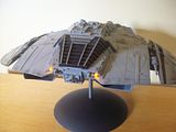
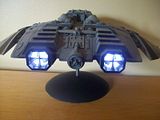
help with.wiring needed. battlestar build

Chosen1

New Member
Hello all,

So.i.was.about 3/4 of the way thru buildimg the.pegasus.and.the.LEDs (half of them) are either dim or have burned out. The strips also have the same issue. I light tested a week ago and it was.fine. but.now no cigar...
Im just wondering.if.maybe there is a particular.wiring/ soldering technique to usewhen building thr different wiring apparatuses and converging them.into a single wire. Any help would be much appreciated.

C1
 
Can you post pictures of your wiring? Did you wire in series or parallel? All reds together and all blacks together? What are you using as a power supply? How many LEDs do you have wired?
 
oh man. i stripped everything b/c I'm rebuilding it so no pics. some where wired in series and some in parallel. The six flickering LEDs for the boosters were all wired in series. separate from the LED strips that were also wired in series once i cut the sections i needed. Then 4 Leds - 2 wired in series on both the upper and lower hull potions, and then 3 lEDs for navigation lights. so all together 12 LED bulbs 5mm. and 6 strips of about 9 lights per strip. I then linked all of the positive and negative ends together for the boosters and other wiring separate. so at the end of all of it. i had 2 positive wires and 2 negatives. The boosters work just fine its just the lighting for the ship thats out.
 
If they were all working at one time, I would say you have a power supply issue...either too much (more likely) or too little.

Jon
 
Sounds to me more like a resistance issue. Unless you use LEDs with built-in resistors, each LED or series run of LEDs must have its own resistance added to the circuit to limit its current. If you wire your circuit through a resistor then split it to LEDs in parallel, the current will often not divide evenly, and one of the LEDs will get too much and eventually fail. If it fails by going open-circuit, another of the LEDs that were in parallel with it will fail soon after in an accelerating cascade -- until either they all fail, or one of them fails by going shorted instead of open.
 
i did use them. but i have a feeeling i used the wrong ones. I went to the LED website where it tells you what resistors to use but its confusing b/c im not sure if adding 12V LEDs to the circuit would affect that and theres no option for that on the site.
 
Go here to figure out your wiring and resistor needs.

http://led.linear1.org/led.wiz

12v LEDs are just regular LEDs that come with a resistor to be used with a 12v power supply.

What type of power supply were you using? Were these all white LEDs?
 
Go here to figure out your wiring and resistor needs.

http://led.linear1.org/led.wiz

12v LEDs are just regular LEDs that come with a resistor to be used with a 12v power supply.

What type of power supply were you using? Were these all white LEDs?


No most of them were white. bUt I also had 1 green LED and 1 Red for the flight pod lights. and i made a mistake earlier. I meant the LED strips were 12V. Do the strips need a resistor too?

- - - Updated - - -

Go here to figure out your wiring and resistor needs.

http://led.linear1.org/led.wiz

12v LEDs are just regular LEDs that come with a resistor to be used with a 12v power supply.

What type of power supply were you using? Were these all white LEDs?

Thats the site im talking about. I wired it up exactly how they told me to w/ the suggested resistors. I have a 12V batter as the power source. IM thinking i need to bring that down to 9V tho.
 
The calculator should have given you how much current your array draws. I'm thinking your 12v battery is being drained too fast causing your LEDs to die out. I would consider rewiring it using a regulated power supply that plugs into a wall outlet. That should give you enough mAH to power your lights without killing batteries. I used an adjustable one I got at RadioShack for about $20 on my Moebius Raider.

 
just bought one. I also got the red and black cords that plug into the machine? Do i just feed the wire from the ship into those cords on the other end?
 
@ Chosen 1

resistor goes on the positive side before the led.....

the leds you are using have different voltage requirements, the whites use 3.5v to 3.6v, the green requires 2.1v and the red uses 2.0v so you will need 2 different voltages to drive the 3 different leds of coarse this is for 20ma diodes to get your resistances .

using the calculator you are using will not give the correct resistances for varying voltage leds , so by this you are either over voltage the red and green which can burn them out, or under voltage the whites which more likely than not be to dim or not light up at all. Since the red and green use 2.0v run those on a parallel circuit independent of the white led circuit, this way you can avoid the above situation I stated.

here is a calculator that gives the voltage per led color;

http://www.hobby-hour.com/electronics/ledcalc.php

and remember that series shares common current but voltage increases per led used and in parallel current increases per how many leds are used but voltage stays the same.

hope this helps you out a bit :)
 
Last edited:
I count 66 to 67 leds total in your array. As I stated before the red, green and yellow leds need 2.1v at 20 ma and the whites need 3.6v at 20 ma to light up at full luminosity.
As I see this you should do each circuit separate in parallel , In this fashion you will be able to calculate what resistance per circuit you will need and not worry about what might get mixed up doing a series/parallel array. Pick a power supply of 4.5v to 6v , wire each setup separately and use the calculator I have above .
Your led white strips are already wired in parallel so consider those as 1 led at 3.6v @180 ma each (20ma x 9 = 180ma x 6 = 1080 ma or 1.1 amp) could be why they were dim).
Draw yourself a simple diagram and go from there.
 
You can use the battery you already have, but if the post above by vidman is correct, that 1 amp of current will drain a battery quickly unless it's something big like a lantern battery or cordless tool battery. You might want to get a 12 volt supply of fairly hefty current capability (2 amps or more).

Then all you need to do is put a resistor of the proper value in series with each LED. The LED strips you mentioned as being 12V should have built-in resistors, so no extra resistors needed for those.

LEDs.png

Calculate each resistor value in ohms as follows: Rx = (Vsupply - Vled) / I led
where Vled is the LED voltage, and I led is the LED current in AMPS -- LED current is usually given in mA (milliamps), so you need to divide it by 1000 to get amps; 20 mA = 0.020 A

You can save resistors and power by putting a few LEDs in series as indicated by the bottom 2 rungs of my ladder diagram. If you have several LEDs that want the same amount of current, you can put a few of them in series so long as their voltages do not add up to more than the supply. To be safe, you should stay at least a couple of volts below the supply value. For example, you could put 4 green LEDs of 2.1 volts and 25 mA in series. To calculate the resistance, add up the voltages (but not the currents). So the calculation for R3 becomes R3 = (12 - 8.4) / 0.025, or 144 ohms. This is not a standard value for common 5% tolerance resistors, so go up to the next standard value which is 150 ohms.

If you put 2 white LEDs of 3.6 volts and 30 mA in series, the calculation gives R4 = (12 - 7.2) / 0.030, or 160 ohms. This is a standard value but not very common, so you will probably have to go up to 180 ohms.

As was mentioned before, it does not matter if the resistors are on the negative side or the positive side. I drew them on the positive side because that's the conventional way of doing it. Same thing with the switch, it does not matter which side of the battery it goes on.

Also, I think we might need more info about those 6 flickering LEDs for the boosters. They might not want to be wired in series.
 
Last edited:
Thanks for the diagram. So I would keep the green and Red LED's seperate right? and wire the white LEDS together?

My mistake there are 8 flickering LEDs. Blue 3V 20ma.
 
Thanks for the diagram. So I would keep the green and Red LED's seperate right? and wire the white LEDS together?
That's up to you. It's OK to wire LEDs of different voltages in series, as long as they all want the same current.

My mistake there are 8 flickering LEDs. Blue 3V 20ma.
I would need to know more than this. Can you provide a link to a full description of this product? I've seen blinking LEDs (not random flickering) that you could put one blinking LED in series with several regular LEDs as long as you didn't exceed a certain supply voltage, and they would all blink at the same time. If your flickering LEDs are like this, it might not be good to put them in series. Also, do you want the boosters to all flicker in synch, or do you want them to be independent?
 
This thread is more than 9 years old.

Your message may be considered spam for the following reasons:

  1. This thread hasn't been active in some time. A new post in this thread might not contribute constructively to this discussion after so long.
If you wish to reply despite these issues, check the box below before replying.
Be aware that malicious compliance may result in more severe penalties.
Back
Top