You are using an out of date browser. It may not display this or other websites correctly.
You should upgrade or use an alternative browser.
You should upgrade or use an alternative browser.
ZK's ZF-1 research thread
- Thread starter Zombie Killer
- Start date
predatorRanger
New Member
ok sounds good,,ill hit him up !!! just wish I could go back a couple years when you guys got all this going and all,, just striving for a accurate gun !!
predatorRanger
New Member
where'd you get your electronics glen,, very impressive !!
Thanks, i designed and built it myself.
predatorRanger
New Member
wow that must have taken a couple months,, when I get to that part, might hit ya up for some note on what circut boards and resistors led's to buy !!! How much longer til your ZF1 is finished ??
Ok got the parts Mars sent and built the frame up as much as i can. First thing, don't tighen any screws down too tight at first. This thing has to be assembled and disassembled a million times. Also i recommend going through the tapped holes with a tap to clean out the treads. Some threads were not tapped as deep as they were supposed to be like the sight crossbar so you'll need to try to get a couple more threads cut into it or you might not be able to tighten down the rear shock front rod ends tot he sight arms. Check them first, one of mine just made it but the other side i had to get a couple threads cleaned out and go as deep as i could by hand before the screw would go in far enough. They were supposed to be done at 20mm to have some room to play but it looks like they only went to 15mm which is right at the limit so you may have to work it. I'll do this in 2 parts as there are 90 pics. You'll need to contact me for the link to the photobucket folder for the pics of the parts and the screws that go with them.
Top plate is going to have to be drilled. All the holes are 2mm. Here is what i drilled them to. You will want to read this whole thread before drilling. If you are mounting the pod down here on the sides you will not want to drill out the edge screws holes. You'll want to drill and tap for the screws because with the tabs you cannot get the nuts on. You will need to tap them to secure the screws.


Something else i did was mod the whale plates. I drilled a 13/64" hole in between 2 holes for the rear hose support bar. You will want to drill it a little higher than here, the screws ended up keeping the rear plate from coming up flush. I also cut the front edge where the red line is because the frame seemed a little long for my pod. I cut this a while back and have no clue how much, I think it was close to 1/8" . Just leave a bit so you don't go into the big hole. If you have already drilled your frame bolt holes you will have to slot them like i did and i also filed the slot so the top plate would go back more. Might be easier to leave that and cut the top plate since it has to be cut anyways.

Then i reassembled the frame to what it was before replacing the top plate. Then i put the 8-32 screw in the rear most hole in the top plate with nuts. I then spaced the rear plate one screw head width back. Which ends up being the back edge of the sideplate.


Then i found out where the first bend was at compared tot he top plate. Made a mark for where to cut.


I used a 2x6 to hold the plate up while i cut. I also cut the front tabs off. I am not mounting the pod at the sides anyways. If you are you will want to drill and tap those outside holes instead of drilling them like i did in the first step..


Then reassembled


Then i flipped it upside down and marked where the 6-32's go and disassembled, drilled and tapped for them and mounted the angles.


Then i put in the other 6-32 ans 8-32 screws with nuts and put nuts on the bracket 6-32s too.


Installed the rear hose support bar to keep the back semi together. I am going to have to replace this screw with a regular socket cap style so it doesn't hit the rear plate.

I put the rear plate back up and marked for the first 2 mounting holes for the 8-32 screws. I drilled 11/64 holes at the following locations.


Drilled them then put the plate back on the frame and used a pencil to mark the place for the hole in the top plate.Then drilled and mounted the plate to the top plate.

Rear plate was a bit short so i had to beat and bend it so it was longer. There was no simple way to do this. I got a piece of 1/2" solid aluminum bar and tried to hammer on the inside of the plates to open the bends up . Any other way and the plates just wanted to bend at the holes. Hopefully a little filing and sand paper will clean it up.


Next thing was to drilled the sidearm rear mounting holes. First i assembled the arms and mounts and bolted the front mount to the sideplate so it was straight to the front edge of the sideplates.

When assembling the arms i noticed one of my rear brackets mounting holes were not drilled in the center of the bracket so when it was together with the spacer it was off by a bunch. I ended up drilling one of the holes bigger to make up for it. It was still a hair off but i couldn't go bigger. i may be able to wobble the drill to make up the last bit. Not sure if you will have this same problem but figure i'd post it incase you do.


With the frame upside down i put the rear mount so it was straight, moved the arm out of the way and marked the mount and hole location using a pencil with lots of lead out.


To hold the plate on better and keep that tab flatter tot the top plate i added another hole further back for another 8-32. This screw is not in the screw kits. We'll have to figure out this screw thing because i ended up having to add some to make this work.


To mount the pod to the frame i plan on 1 at the front and the mount at the back. I doubt i will put anything on the sides. The sides may work better for you though. All depends on how you wantt to do it. I'll just show what i came up with, your mileage may vary.
I mounted a plate to the top of my pod with screws and will have a stud sticking out of the middle hole to screw to the frame bracket.


For the frame i used the little brakets i sent out. I mounted the front shcok mounts to the plates and marked their location on the top plate. Then took the brackets and centered them in those boxes and marked it, then quartered the box for mounting screw locations. These sacrews are also not in the kit as i didn't plan on doing it this way. I got some at the local fastener store. Probably could have bout a box of them for the price these guy charge locally.


Drilled holes for 4-40 flat head screws to go through then put the brackets on the other side where they willl sit and marked the holes for them. I drilled and taped the angle brackets for 4-40 screws. Then counter sunk the holes in the plate. I guess the best way is to make a hoop of sorts with a hole at the top for the pod stud to go through and then make the legs the right size for the pod to come down and then drill and tap for screws to attach the hoop to the angle brackets.


Top plate is going to have to be drilled. All the holes are 2mm. Here is what i drilled them to. You will want to read this whole thread before drilling. If you are mounting the pod down here on the sides you will not want to drill out the edge screws holes. You'll want to drill and tap for the screws because with the tabs you cannot get the nuts on. You will need to tap them to secure the screws.
Something else i did was mod the whale plates. I drilled a 13/64" hole in between 2 holes for the rear hose support bar. You will want to drill it a little higher than here, the screws ended up keeping the rear plate from coming up flush. I also cut the front edge where the red line is because the frame seemed a little long for my pod. I cut this a while back and have no clue how much, I think it was close to 1/8" . Just leave a bit so you don't go into the big hole. If you have already drilled your frame bolt holes you will have to slot them like i did and i also filed the slot so the top plate would go back more. Might be easier to leave that and cut the top plate since it has to be cut anyways.
Then i reassembled the frame to what it was before replacing the top plate. Then i put the 8-32 screw in the rear most hole in the top plate with nuts. I then spaced the rear plate one screw head width back. Which ends up being the back edge of the sideplate.
Then i found out where the first bend was at compared tot he top plate. Made a mark for where to cut.
I used a 2x6 to hold the plate up while i cut. I also cut the front tabs off. I am not mounting the pod at the sides anyways. If you are you will want to drill and tap those outside holes instead of drilling them like i did in the first step..
Then reassembled
Then i flipped it upside down and marked where the 6-32's go and disassembled, drilled and tapped for them and mounted the angles.
Then i put in the other 6-32 ans 8-32 screws with nuts and put nuts on the bracket 6-32s too.
Installed the rear hose support bar to keep the back semi together. I am going to have to replace this screw with a regular socket cap style so it doesn't hit the rear plate.
I put the rear plate back up and marked for the first 2 mounting holes for the 8-32 screws. I drilled 11/64 holes at the following locations.
Drilled them then put the plate back on the frame and used a pencil to mark the place for the hole in the top plate.Then drilled and mounted the plate to the top plate.
Rear plate was a bit short so i had to beat and bend it so it was longer. There was no simple way to do this. I got a piece of 1/2" solid aluminum bar and tried to hammer on the inside of the plates to open the bends up . Any other way and the plates just wanted to bend at the holes. Hopefully a little filing and sand paper will clean it up.
Next thing was to drilled the sidearm rear mounting holes. First i assembled the arms and mounts and bolted the front mount to the sideplate so it was straight to the front edge of the sideplates.
When assembling the arms i noticed one of my rear brackets mounting holes were not drilled in the center of the bracket so when it was together with the spacer it was off by a bunch. I ended up drilling one of the holes bigger to make up for it. It was still a hair off but i couldn't go bigger. i may be able to wobble the drill to make up the last bit. Not sure if you will have this same problem but figure i'd post it incase you do.
With the frame upside down i put the rear mount so it was straight, moved the arm out of the way and marked the mount and hole location using a pencil with lots of lead out.
To hold the plate on better and keep that tab flatter tot the top plate i added another hole further back for another 8-32. This screw is not in the screw kits. We'll have to figure out this screw thing because i ended up having to add some to make this work.
To mount the pod to the frame i plan on 1 at the front and the mount at the back. I doubt i will put anything on the sides. The sides may work better for you though. All depends on how you wantt to do it. I'll just show what i came up with, your mileage may vary.
I mounted a plate to the top of my pod with screws and will have a stud sticking out of the middle hole to screw to the frame bracket.
For the frame i used the little brakets i sent out. I mounted the front shcok mounts to the plates and marked their location on the top plate. Then took the brackets and centered them in those boxes and marked it, then quartered the box for mounting screw locations. These sacrews are also not in the kit as i didn't plan on doing it this way. I got some at the local fastener store. Probably could have bout a box of them for the price these guy charge locally.
Drilled holes for 4-40 flat head screws to go through then put the brackets on the other side where they willl sit and marked the holes for them. I drilled and taped the angle brackets for 4-40 screws. Then counter sunk the holes in the plate. I guess the best way is to make a hoop of sorts with a hole at the top for the pod stud to go through and then make the legs the right size for the pod to come down and then drill and tap for screws to attach the hoop to the angle brackets.
Next thing i did was countersink the rear shock mounting bar screws. To do this i had to cut down the 4-40 screws a little. I used the old rear plate thingie and screwed the screws into it with nuts and then ground off the excess screw. I do it this way so the nut cleans the threads as you unscrew it.


Next i assembled the rear shocks. I screwed in the rear rod end to the rear cap so it was tight and then marked the holes in line with the edge of the rodend and put it 3/16" infrom the edge of the cap. I marked the front cap too. It's location is less critical because you can locate it after in line with the rear.

I put in the tube. (Rear shocks use the longer tubes front shocks have the short tubes.) and then drilled the cap and tube at the same time. Then i tapped them for 4-40x 1/8 setscrews at the same time. Bought the setscrews at the fasntener store.

Then i used a piece of tape to line the rear set screw up to he front one and then drilled and tapped the front holes. Then took them apart and cleaned them out and took out and burrs on the inside.

I'll use the screws from the hose cross bar in the shocks to keep them from coming out.


For the front shocks i inserted the short tube into the shock mount and made a mark for where to drill the hole in the tube for the setscrews. I don't have front shock caps so i can't mount them or the barrel. You will have to look at mars' build for that part.

I ended up cutting my whales a while back while experimenting and screwed myself. Your whales will be taller here. I don't see anyway around the fact you will need to drill 2 holes to attach the plates to the rear shock mounts. I would probably do it somewhere around where i have the red X. Probably go with a stainless countersunk screw so it is less visible. Also the 2 screws just sitting at the top will need to be screwed into the wood block that gets mounted to the pod there. These screws may have to be replaced with shorter ones if there is problems getting them in due to clearance. Might be easier to screw them to the wood then drop the pod down and screw the pod to the wood. Then the screws will have to be covered before painting. These screws are on the original pods, the pod screws are barely visible because they are covered then painted.


For the front parts i was going to cut some hardwood pieces to space the brass and side block apart but they just kept shattering as it was too hard. I just found some 1/4" thick regular wood and made a small spacer.

Don't forget the little locating pin on the bottom of the rocket block

I had to file off a little on the brass piece to clear the screw. I don't have one of the nuts that goes under it anymore.

Here is what it looks like assembled. Ignore the extra hole in the rocket block , i had to do that for the live fire one i am building.


I think we went through the lower brass parts before. you'll need to sand down the brass tube coming out of the clippard cylinder to fit in the bottom of the brass block and screw in the little square valve to the bottom of the cylinder. I don't have those brass cylinders that i made with the tubes so you'll have to look at the parts pics to see where they go. The lower blue tube gets screwed in with the 4-40x5/8 screw and the nozzle goes on with the 6mm stud i think mars had supplied. After fitting your probably better off unscrewing the nozzle so it doesn't get messed up. Put it and the blue nozzle on last or close to it.

For the blue nozzle you can just unscrew one of the mounting bar screws and slide it on and lift it up so the tube goes into it.

My rocket is cut for the live fire so it is slotted for the magazine making it a bit easier to put a nut on the inside. There are no slots on the live fire tube so that will be different too. You may have to drill and tap the rocket tube for this mount to work.
I bought some 1/4" aluminum tube with .049 wall. Sanded down the perimeter a little so it fit into the hole at tthe top of the rocket mount. Then i took a 6-32 allen and stuck it all the way into the hole and tightened the setscrew in the mount on it to hold it , put a nut on it so i knew how far deep it went. Then pulled it out and made a spacer to fit. Then i screwed it into the bottom of the rocket 1 7/8" from the edge of the tube where the rocket nose cone is and used a nut on the inside.


Then i stuck it back on the mount and tightened the setscrew again.

This is where i cut the torch to use the front part. I am not sure about this part yet but i'll probably JBweld another brass tube in the aluminum one and make a spacer or something to go over the tube and so the torch part fits over. The tube just slides into the lower blue block and gets secured with the lower of the 2 button head screws.


Thats about all i can do right now. You'll have to file or grind or sand the top plate and rear plate or/and the pod so the pod will go over them and sit on the pod. You may also want to use side mounts rather then the front ones like i did. The sight and it's workings you'll need to follow Marcels thread as he is tackling that now. Between this and Marcels build you should be able to build this thing up.
OK so where did the weekend go.....
Next i assembled the rear shocks. I screwed in the rear rod end to the rear cap so it was tight and then marked the holes in line with the edge of the rodend and put it 3/16" infrom the edge of the cap. I marked the front cap too. It's location is less critical because you can locate it after in line with the rear.
I put in the tube. (Rear shocks use the longer tubes front shocks have the short tubes.) and then drilled the cap and tube at the same time. Then i tapped them for 4-40x 1/8 setscrews at the same time. Bought the setscrews at the fasntener store.
Then i used a piece of tape to line the rear set screw up to he front one and then drilled and tapped the front holes. Then took them apart and cleaned them out and took out and burrs on the inside.
I'll use the screws from the hose cross bar in the shocks to keep them from coming out.
For the front shocks i inserted the short tube into the shock mount and made a mark for where to drill the hole in the tube for the setscrews. I don't have front shock caps so i can't mount them or the barrel. You will have to look at mars' build for that part.
I ended up cutting my whales a while back while experimenting and screwed myself. Your whales will be taller here. I don't see anyway around the fact you will need to drill 2 holes to attach the plates to the rear shock mounts. I would probably do it somewhere around where i have the red X. Probably go with a stainless countersunk screw so it is less visible. Also the 2 screws just sitting at the top will need to be screwed into the wood block that gets mounted to the pod there. These screws may have to be replaced with shorter ones if there is problems getting them in due to clearance. Might be easier to screw them to the wood then drop the pod down and screw the pod to the wood. Then the screws will have to be covered before painting. These screws are on the original pods, the pod screws are barely visible because they are covered then painted.
For the front parts i was going to cut some hardwood pieces to space the brass and side block apart but they just kept shattering as it was too hard. I just found some 1/4" thick regular wood and made a small spacer.
Don't forget the little locating pin on the bottom of the rocket block
I had to file off a little on the brass piece to clear the screw. I don't have one of the nuts that goes under it anymore.
Here is what it looks like assembled. Ignore the extra hole in the rocket block , i had to do that for the live fire one i am building.
I think we went through the lower brass parts before. you'll need to sand down the brass tube coming out of the clippard cylinder to fit in the bottom of the brass block and screw in the little square valve to the bottom of the cylinder. I don't have those brass cylinders that i made with the tubes so you'll have to look at the parts pics to see where they go. The lower blue tube gets screwed in with the 4-40x5/8 screw and the nozzle goes on with the 6mm stud i think mars had supplied. After fitting your probably better off unscrewing the nozzle so it doesn't get messed up. Put it and the blue nozzle on last or close to it.
For the blue nozzle you can just unscrew one of the mounting bar screws and slide it on and lift it up so the tube goes into it.
My rocket is cut for the live fire so it is slotted for the magazine making it a bit easier to put a nut on the inside. There are no slots on the live fire tube so that will be different too. You may have to drill and tap the rocket tube for this mount to work.
I bought some 1/4" aluminum tube with .049 wall. Sanded down the perimeter a little so it fit into the hole at tthe top of the rocket mount. Then i took a 6-32 allen and stuck it all the way into the hole and tightened the setscrew in the mount on it to hold it , put a nut on it so i knew how far deep it went. Then pulled it out and made a spacer to fit. Then i screwed it into the bottom of the rocket 1 7/8" from the edge of the tube where the rocket nose cone is and used a nut on the inside.
Then i stuck it back on the mount and tightened the setscrew again.
This is where i cut the torch to use the front part. I am not sure about this part yet but i'll probably JBweld another brass tube in the aluminum one and make a spacer or something to go over the tube and so the torch part fits over. The tube just slides into the lower blue block and gets secured with the lower of the 2 button head screws.
Thats about all i can do right now. You'll have to file or grind or sand the top plate and rear plate or/and the pod so the pod will go over them and sit on the pod. You may also want to use side mounts rather then the front ones like i did. The sight and it's workings you'll need to follow Marcels thread as he is tackling that now. Between this and Marcels build you should be able to build this thing up.
OK so where did the weekend go.....
lol...oops
")
I started disassembling mine completely yesterday. It's hard to work much on it in my unheated shop, but I'm starting to get a little overwhelmed. Hopefully these new pics will help a bit.
I may be able to offer a build service for the guys in the US if it is too much for anyone to handle.
All of this beautiful work reminds me that I am still missing a rocket tube. I have fins and tip, just no tube (slotted for the fins?) I am happy to buy blank tubing and slot it myself but if I can still get a properly machined one it would be better. Can anyone help?
Thanks!
Steve
Thanks!
Steve
I'm late to the game as always, but just had this nostalgia trip and saw youtube clips from making of. I'm curious, was there ever a prop that could transform or was it just "after effects"? Looking at the sequence in still frames, it seems they just took the plate and cut up the pieces and animated them for this one shot. Though, very nicely done.
As are your work
As are your work
Fnordcorps
New Member
Hi all,
I was brought here strangely by a link via Adam Savages video on making his own ZF1. I noticed a few of you in this thread talking about the 'History Channel' ZF1 that many of you have been using as influence for building your own.
Just thought you may be interested in a little history behind it - as I was the one who built it.
As some of you have noticed that particular one was slightly inaccurate.
I was doing work experience on my second year of my modelmaking degree at Hatfield university. I managed to land work experience in the armoury department on Band of Brothers under Simon Atherton (one of the armourers on The Fifth Element). I was looking for a 3rd year final project to make and I noticed Simon had the original closed ZF1 pod master and some of the spare componants in a storage container and asked him if he minded if I used his pattern to take moulds off and make an 'open' version of the ZF1 for my uni project.
He agreed to let me borrow the pod and allowed me to measure all the componant parts left he had to make my own. I then over the space of a month built the ZF1 that you see him holding in the history channel documentary. I know because I was in the next room while they were shooting it. We were working at Elstree studios at the time on Troy and because they did not have access to any of the original ZF1's Simon asked if he could borrow mine for the interview purposes.
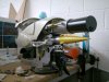
I have attached many of my working photos here for your interest. The pod shown here is the original template sculpted to make all the original ZF1's. I also measured and copied many of Simons parts and copied them as closely as I could. Many of the discrepancies many of you seem to have noticed was due to me very much using the same method as you guys to build it - screengrabbing the dvd and interpreting it as best as I could. The only difference being I could run things via Simon to see if I was doing it right as I went.
Also there were around 8 different versions of the ZF1 built - One for needles, one to take a blank firing gun, flamethrower version, net launcher version, dry ice version etc. Between armoury and SFX they built a version to do everything as it was easier than trying to fit all the rigs for each effect all in one. I dont know exactly how many they made but I have spoken to Simon and NIck Finlasson, who worked on the sfx side of the gune many times about this gun when hanging around on film sets.
I still have all the pieces from my original including two copies of all the shell parts cast from the original shell. Also when Simon was having a clear out one day some of the smaller componant parts were going in the skip which I salvaged and still have in a box in my workshop container. I also have one of the original net launchers that still has the net coiled up inside it.
My container just went into storage today, unfortunately for a couple of weeks but as soon as I get in there again I will try and dig out the original parts I have and photographe them for your research.
These days I now run the Armoury department as head of department on many big movies and still make weapons for films full time. Been doing it now for around 17 years.
Here are the images of my build with some original parts - please do not judge, I was a second year modelmaking student at university, doing this on a poor student budget and some of this makes me cringe!


- - - Updated - - -
And more images


I was brought here strangely by a link via Adam Savages video on making his own ZF1. I noticed a few of you in this thread talking about the 'History Channel' ZF1 that many of you have been using as influence for building your own.
Just thought you may be interested in a little history behind it - as I was the one who built it.
As some of you have noticed that particular one was slightly inaccurate.
I was doing work experience on my second year of my modelmaking degree at Hatfield university. I managed to land work experience in the armoury department on Band of Brothers under Simon Atherton (one of the armourers on The Fifth Element). I was looking for a 3rd year final project to make and I noticed Simon had the original closed ZF1 pod master and some of the spare componants in a storage container and asked him if he minded if I used his pattern to take moulds off and make an 'open' version of the ZF1 for my uni project.
He agreed to let me borrow the pod and allowed me to measure all the componant parts left he had to make my own. I then over the space of a month built the ZF1 that you see him holding in the history channel documentary. I know because I was in the next room while they were shooting it. We were working at Elstree studios at the time on Troy and because they did not have access to any of the original ZF1's Simon asked if he could borrow mine for the interview purposes.
I have attached many of my working photos here for your interest. The pod shown here is the original template sculpted to make all the original ZF1's. I also measured and copied many of Simons parts and copied them as closely as I could. Many of the discrepancies many of you seem to have noticed was due to me very much using the same method as you guys to build it - screengrabbing the dvd and interpreting it as best as I could. The only difference being I could run things via Simon to see if I was doing it right as I went.
Also there were around 8 different versions of the ZF1 built - One for needles, one to take a blank firing gun, flamethrower version, net launcher version, dry ice version etc. Between armoury and SFX they built a version to do everything as it was easier than trying to fit all the rigs for each effect all in one. I dont know exactly how many they made but I have spoken to Simon and NIck Finlasson, who worked on the sfx side of the gune many times about this gun when hanging around on film sets.
I still have all the pieces from my original including two copies of all the shell parts cast from the original shell. Also when Simon was having a clear out one day some of the smaller componant parts were going in the skip which I salvaged and still have in a box in my workshop container. I also have one of the original net launchers that still has the net coiled up inside it.
My container just went into storage today, unfortunately for a couple of weeks but as soon as I get in there again I will try and dig out the original parts I have and photographe them for your research.
These days I now run the Armoury department as head of department on many big movies and still make weapons for films full time. Been doing it now for around 17 years.
Here are the images of my build with some original parts - please do not judge, I was a second year modelmaking student at university, doing this on a poor student budget and some of this makes me cringe!
- - - Updated - - -
And more images
Attachments
Last edited:
Thanks you for this info, very nice of you to join this thread.
The pictures are great also. Its a very nice model indeed, esp as you were making it on your own.
Were the shell moulds in separate parts? Alot of the folks here have casts from the closed shell and are having to cut them apart and join the two sides, which is a bit of a nightmare.
The pictures are great also. Its a very nice model indeed, esp as you were making it on your own.
Were the shell moulds in separate parts? Alot of the folks here have casts from the closed shell and are having to cut them apart and join the two sides, which is a bit of a nightmare.
KramStaar
Sr Member
A great video of Adam talking about his finished ZF-1 with big shout-outs for Marcel, Matt and the RPF.
Killer work everyone.
https://www.youtube.com/watch?v=MuNMeLwXPeg
Killer work everyone.
https://www.youtube.com/watch?v=MuNMeLwXPeg
Similar threads
- Replies
- 5
- Views
- 983
- Replies
- 37
- Views
- 4,823
- Replies
- 12
- Views
- 1,402
- Replies
- 0
- Views
- 329