JakeConhale
New Member
Over the COVID lockdown, I had a lot of spare time on my hands and decided I'd put my new 3d printer to the test.
People of culture may remember a Sci-fi show a ways back called Sliders - a group of folks testing out a device allowing passage to alternate dimensions become lost and are seeking their way home. It's a lot like Quantum Leap, actually.
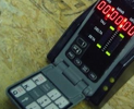
Over the course of the series, they used a device known as a "timer" to hop dimensions. The first one looked like this:

It was built into a particular brand of cellphone. (Though never stated, I suspect the rationale was to allow the characters to interact with the device in public while not drawing undue attention, people would just assume someone was fiddling with their phone). The top set of digits indicated how many days until the next "Slide" - on the original prop this was just a static display, the lower set of digits displayed hours, minutes, and seconds until the display, and the rest were basically blinkies to make it look like it was doing something impressive. The circular section above the "earpiece" was a power or intensity indicator.
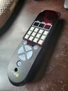
Anyways, here's my build:

The unit is powered by an arduino nano and a 9v battery. I was able to find a particular 3 digit clock display that I could flip upside down to complete the hours/minutes/seconds display as well as the days remaining.
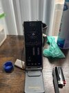
I designed and order a custom circuit board for the build. It turned out... alright. There were some errors in the design (all my fault) but nothing I couldn't work around. (the power jack port pins were completely the wrong way around, for example, and rather than being soldered to the board, the jack had to be connected through wires)

The initial plan was just to have the power knob be completely disconnected, as I didn't know what I could do with it. I found an 8-way rotary switch on adafruit and was able to turn it into the power switch. I also found a ring like on Adafruit and, with the help of a voltage divider circuit, was able to repurpose the power display from an intensity dial to a battery power indicator. Rather proud of that.
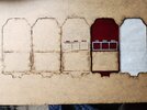
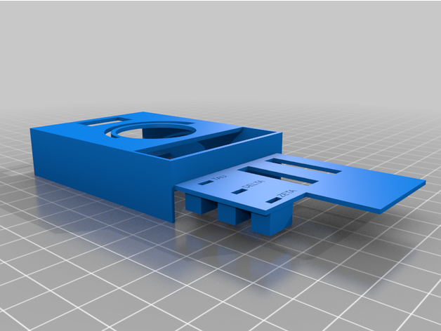
After that was said and done, I printed the top and bottom using a notch connection design I found online, and was able to assemble the thing:
 .
.

The HH:MM:SS display is red LEDs under red glass cut to size using the score-and-snap method. The keypad is functional and one is able to input a desired time. The device actually has a number of functions:
I think I need to adjust my settings on the 3d printer, the print came out with more striations than I had anticipated, not sure it's quite getting sufficiently hot. Meant to have a keypad cover but the mounting arms broke so I need to revisit that design. I also need to actually implement the wormhole generator at the top pf the unit, but I have ideas on that.
Anyways, what do ya'll think?
People of culture may remember a Sci-fi show a ways back called Sliders - a group of folks testing out a device allowing passage to alternate dimensions become lost and are seeking their way home. It's a lot like Quantum Leap, actually.
Over the course of the series, they used a device known as a "timer" to hop dimensions. The first one looked like this:
It was built into a particular brand of cellphone. (Though never stated, I suspect the rationale was to allow the characters to interact with the device in public while not drawing undue attention, people would just assume someone was fiddling with their phone). The top set of digits indicated how many days until the next "Slide" - on the original prop this was just a static display, the lower set of digits displayed hours, minutes, and seconds until the display, and the rest were basically blinkies to make it look like it was doing something impressive. The circular section above the "earpiece" was a power or intensity indicator.
Anyways, here's my build:
The unit is powered by an arduino nano and a 9v battery. I was able to find a particular 3 digit clock display that I could flip upside down to complete the hours/minutes/seconds display as well as the days remaining.
I designed and order a custom circuit board for the build. It turned out... alright. There were some errors in the design (all my fault) but nothing I couldn't work around. (the power jack port pins were completely the wrong way around, for example, and rather than being soldered to the board, the jack had to be connected through wires)
The initial plan was just to have the power knob be completely disconnected, as I didn't know what I could do with it. I found an 8-way rotary switch on adafruit and was able to turn it into the power switch. I also found a ring like on Adafruit and, with the help of a voltage divider circuit, was able to repurpose the power display from an intensity dial to a battery power indicator. Rather proud of that.
After that was said and done, I printed the top and bottom using a notch connection design I found online, and was able to assemble the thing:
The HH:MM:SS display is red LEDs under red glass cut to size using the score-and-snap method. The keypad is functional and one is able to input a desired time. The device actually has a number of functions:
- The sliders Timer function, including a randomly generated new time after every "slide", assuming you do slide, otherwise you'll be stranded for the next 27 years.
- A clock function
- An options page, allowing one to turn the sound on/off, change the boot sequence between original and Egyptian displays, whether or not to flash the LED blinkies, adjust brightness, and how long to wait before going to "sleep".
I think I need to adjust my settings on the 3d printer, the print came out with more striations than I had anticipated, not sure it's quite getting sufficiently hot. Meant to have a keypad cover but the mounting arms broke so I need to revisit that design. I also need to actually implement the wormhole generator at the top pf the unit, but I have ideas on that.
Anyways, what do ya'll think?