You are using an out of date browser. It may not display this or other websites correctly.
You should upgrade or use an alternative browser.
You should upgrade or use an alternative browser.
One-Sixth Studio Scale TOS Enterprise
- Thread starter Shaw
- Start date
Shaw
Well-Known Member
Thanks!
Yeah, I know right now a lot of this is covering stuff that has been covered many times before (though this stuff doesn't get old for me)... but I'm hoping that when I start to detail the non-filming side's features it'll spark more interest.
This is mainly a test (at two-thirds scale) of what I've been planning on doing when I attempt my one-to-one scale build of the 33 inch TOS Enterprise. I figured that this model and the Phase II Enterprise provided a scaled down way of testing out ideas I had before investing a lot more money on a larger project. It is one thing to think that a plan might work, but getting to test it once or twice on a smaller scale first helps remove the worry that I didn't plan it out correctly.
Right now I'm debating moving from the Mold Star 16 FAST to the Mold Star 15 when I start working on the 33 inch TOS Enterprise because it'll give me more working time. And I'm not as skittish about my masters being damaged as I was originally (the idea of that much work being under a fluid that I may have mixed wrong had me worrying).
Yeah, I know right now a lot of this is covering stuff that has been covered many times before (though this stuff doesn't get old for me)... but I'm hoping that when I start to detail the non-filming side's features it'll spark more interest.
I'm using Mold Star 16 FAST Gallon Unit, and the three molds I just made used up about 35-40% of that. I had used the Mold Star 16 FAST Trial Unit for the Phase II Enterprise parts and it was just barely enough to make those molds. To close in the remaining open volume of the containment boxes I used Woodland Scenics C1201 Lightweight Hydrocal (which is also what I used to help build the masters).What type of silicone are you using? I do not recognize the color.
This is mainly a test (at two-thirds scale) of what I've been planning on doing when I attempt my one-to-one scale build of the 33 inch TOS Enterprise. I figured that this model and the Phase II Enterprise provided a scaled down way of testing out ideas I had before investing a lot more money on a larger project. It is one thing to think that a plan might work, but getting to test it once or twice on a smaller scale first helps remove the worry that I didn't plan it out correctly.
Right now I'm debating moving from the Mold Star 16 FAST to the Mold Star 15 when I start working on the 33 inch TOS Enterprise because it'll give me more working time. And I'm not as skittish about my masters being damaged as I was originally (the idea of that much work being under a fluid that I may have mixed wrong had me worrying).
Shaw
Well-Known Member
Quick update...
I made the upper and lower primary hull parts. I also added the turbo lift to the bridge and gave all of the parts a first coat of primer. In the shots below I included the AMT Cutaway upper and lower primary hull parts for a scale reference.
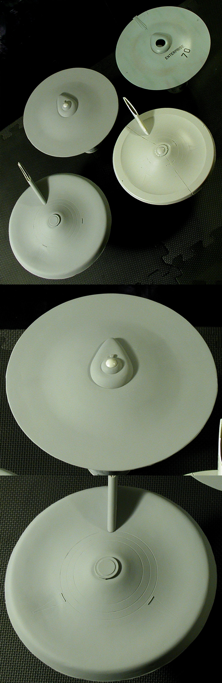
The dorsal and bridge/B/C deck parts are just set in place, I haven't started gluing anything together yet.
I made the upper and lower primary hull parts. I also added the turbo lift to the bridge and gave all of the parts a first coat of primer. In the shots below I included the AMT Cutaway upper and lower primary hull parts for a scale reference.
The dorsal and bridge/B/C deck parts are just set in place, I haven't started gluing anything together yet.
Shaw
Well-Known Member
Thanks!
So I took a series of shots of the primary hull put together (all parts are just sitting in place, no gluing yet) so I could do comparisons with reference images I have. I'm not expecting perfection at this point. The parts have been pulled from their molds, trimmed a little and hit with a coat of primer, but this is the first time I've been able to see the parts all working together (something I couldn't do with the masters).
Here is a selection of the ones that looked the best (as in worth sharing)...
I generally don't show the messier side of these parts, but Albertese asked if I was making these parts solid, so I figured I'd show what the insides of them looked like (so you guys can get a feel for how I'm making them).

So yeah, these aren't solid or even very thick, but they are pretty strong. This is the same method I used for making the bridge/B/C deck and nacelles of my Phase II Enterprise.
So I took a series of shots of the primary hull put together (all parts are just sitting in place, no gluing yet) so I could do comparisons with reference images I have. I'm not expecting perfection at this point. The parts have been pulled from their molds, trimmed a little and hit with a coat of primer, but this is the first time I've been able to see the parts all working together (something I couldn't do with the masters).
Here is a selection of the ones that looked the best (as in worth sharing)...
I generally don't show the messier side of these parts, but Albertese asked if I was making these parts solid, so I figured I'd show what the insides of them looked like (so you guys can get a feel for how I'm making them).
So yeah, these aren't solid or even very thick, but they are pretty strong. This is the same method I used for making the bridge/B/C deck and nacelles of my Phase II Enterprise.
LordSarvain
New Member
Awesome as always!
Shaw
Well-Known Member
Thanks!
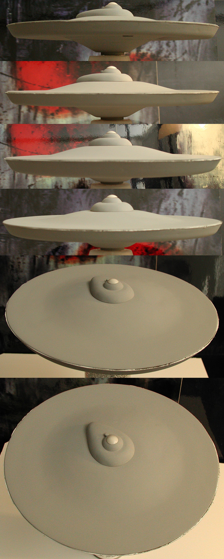
Spent some time making adjustments to the primary hull parts today (mainly the edge of the lower primary hull). Here are a series of images with the parts set in place so I can see how my work has progressed.
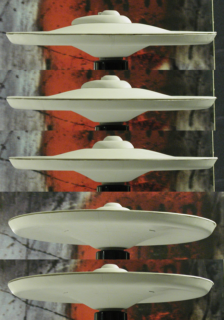
I know it isn't a big difference from the previous series, but I thought I'd share some of the images anyways.
Spent some time making adjustments to the primary hull parts today (mainly the edge of the lower primary hull). Here are a series of images with the parts set in place so I can see how my work has progressed.
I know it isn't a big difference from the previous series, but I thought I'd share some of the images anyways.
Shaw
Well-Known Member
Some more adjustments to the primary hull parts and testing the anchoring system I'll be using to join the primary hull, dorsal and secondary hull. Here are a couple of images with the primary hull parts and dorsal together (nothing is glued yet).
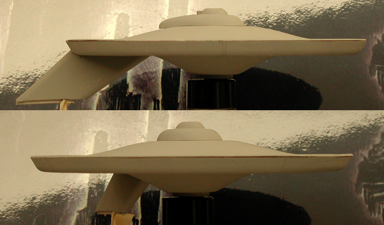
The anchoring system is the same as I used in the Phase II Enterprise (coat hanger wire anchored in both the primary and secondary hulls fed through the dorsal), which is over kill for this model as the primary hull weighs a fraction of that of my Phase II primary hull.
The anchoring system is the same as I used in the Phase II Enterprise (coat hanger wire anchored in both the primary and secondary hulls fed through the dorsal), which is over kill for this model as the primary hull weighs a fraction of that of my Phase II primary hull.
Shaw
Well-Known Member
I did a second quick-n-dirty color test... this time with a spare warp nacelle. This was done (like the upper primary hull) with stuff I had on hand (including decals that are too old... which was why I didn't have all the numbers on the primary hull). So this is actually the second test, I didn't get what I wanted with the colors I used the first time, so I changed it up a bit.
So here is the test...
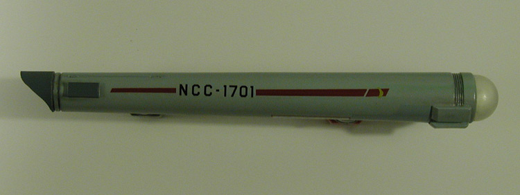
The base hull color is (again) Luftwaffe Light Blue (AS-5). The rear parts are done in Ocean Gray (AS-31) and I added on the same styrene I used for my masters so I could see how the color would work under the same conditions... and I'm happy with the results. The gray area under the front of the nacelle was why I started over. I first tried Medium Sea Grey (AS-11), but it was too dark and stood out way too much for the 11 foot model. For my second attempt I used Light Ghost Grey (AS-26) and that blends in the same way that the original color did on the original model.
I put a final coat of gloss on the test nacelle and then took it back with a couple coats of matte finish (basically the same steps I used on the top primary hull color test). Here is the color test nacelle as it currently stands with the top primary hull included for color comparison/reference.
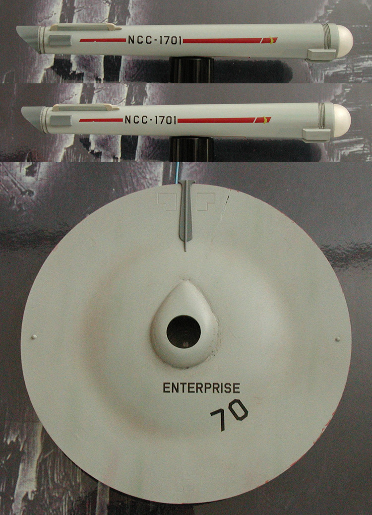
These were shot in daylight… cloudy/snowy daylight, but daylight none the less.
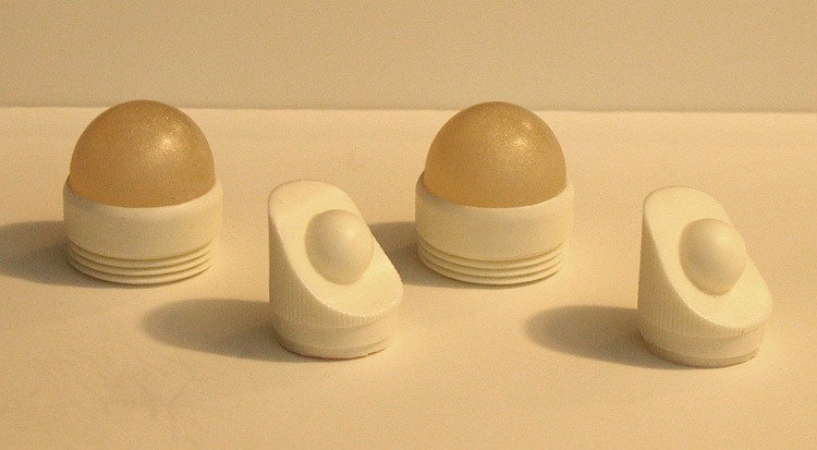
As for the model itself, I made molds of the nacelle domes and did a quick test run to see how they'd turn out as far as size/shape (the mold was thick, so I wasn't expecting any distortions).
Below is a shot of the master spheres, the mold and the first test pulls, and a test dome with my front nacelle master.
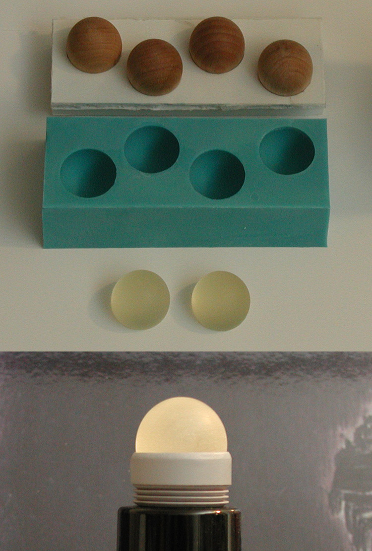
The clear resin isn't as straight forward as the Alumilite White that I'm using for the rest of the parts, so I'm taking some time to get familiar with it.
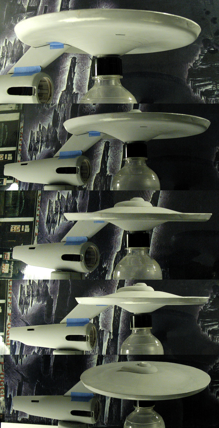
I closed up the primary hull and started in on fixing surface flaws and sharpening up the primary hull's edge.
I wanted to see the primary hull with more than just the dorsal, so I added in the secondary hull in this series of images...
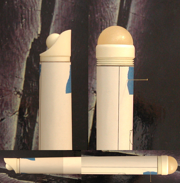
I finally finished with the front and rear nacelle masters and made the molds. Here are the parts that I pulled from them…
I'm not sure if those are the final domes or not, but they do have the effect I'll be attempting to achieve when I do the 33 inch Enterprise replica. With those parts ready I can start in on making the nacelle bodies.
So here is the test...
The base hull color is (again) Luftwaffe Light Blue (AS-5). The rear parts are done in Ocean Gray (AS-31) and I added on the same styrene I used for my masters so I could see how the color would work under the same conditions... and I'm happy with the results. The gray area under the front of the nacelle was why I started over. I first tried Medium Sea Grey (AS-11), but it was too dark and stood out way too much for the 11 foot model. For my second attempt I used Light Ghost Grey (AS-26) and that blends in the same way that the original color did on the original model.
I put a final coat of gloss on the test nacelle and then took it back with a couple coats of matte finish (basically the same steps I used on the top primary hull color test). Here is the color test nacelle as it currently stands with the top primary hull included for color comparison/reference.
These were shot in daylight… cloudy/snowy daylight, but daylight none the less.
As for the model itself, I made molds of the nacelle domes and did a quick test run to see how they'd turn out as far as size/shape (the mold was thick, so I wasn't expecting any distortions).
Below is a shot of the master spheres, the mold and the first test pulls, and a test dome with my front nacelle master.
The clear resin isn't as straight forward as the Alumilite White that I'm using for the rest of the parts, so I'm taking some time to get familiar with it.
I closed up the primary hull and started in on fixing surface flaws and sharpening up the primary hull's edge.
I wanted to see the primary hull with more than just the dorsal, so I added in the secondary hull in this series of images...
I finally finished with the front and rear nacelle masters and made the molds. Here are the parts that I pulled from them…
I'm not sure if those are the final domes or not, but they do have the effect I'll be attempting to achieve when I do the 33 inch Enterprise replica. With those parts ready I can start in on making the nacelle bodies.
Shaw
Well-Known Member
I drew up a template for the nacelle bodies and threw together a mock-up to see how it worked with the parts I made. Here is how that test turned out…
I then used the templates to cut out sections from an Estes model rocket tube and pieced them together (not glued, just taped for now). Here is that first nacelle body test with the front and rear nacelle parts in place (and the spare nacelle from the 22 inch Cutaway kit I used for the color tests).
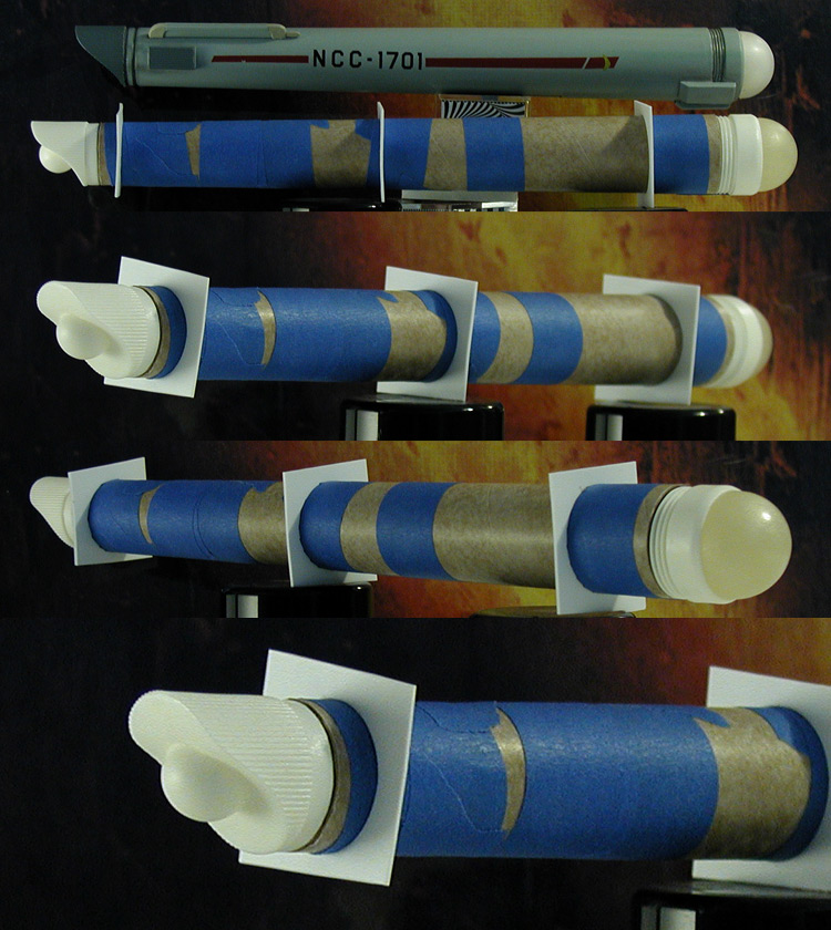
I'm still considering my options at this point as I do need to make one nacelle with the inboard channel as a physical feature.
I then used the templates to cut out sections from an Estes model rocket tube and pieced them together (not glued, just taped for now). Here is that first nacelle body test with the front and rear nacelle parts in place (and the spare nacelle from the 22 inch Cutaway kit I used for the color tests).
I'm still considering my options at this point as I do need to make one nacelle with the inboard channel as a physical feature.
crackerjazz
Sr Member
Hi Shaw - really like your dedication and quest for perfection.
Shaw
Well-Known Member
Thanks guys!
Small update...
I made the initial cut for the inboard channel and glued the body pieces together. It still needs internal support (I'm using a couple stand-in pieces of styrene in the images below), but it'll need to be designed to work with the channel elements (which I haven't started yet). To get a feel for how the final elements will all work together I added on the DLM intercoolers (I'm still a ways from making those parts) and mocked up the front box features. Nothing is glued together, I'm mainly using double sided tape to keep the elements in place in the series of images below.
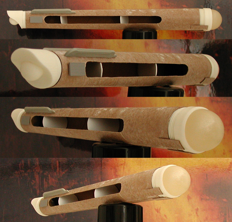
I'll build the other nacelle body today. It should be easier than the first as it won't include the inboard channel.
Once I have both nacelle bodies essentially done I'll go back over the project and take an inventory of what has been made, what needs work and what hasn't been started yet. This should make it easier to plan out making/finishing additional parts that need to have molds made of them (most of which can be grouped together).
Wow, that means a lot to me coming from you. I've been following your LM build for inspiration.Hi Shaw - really like your dedication and quest for perfection.
Small update...
I made the initial cut for the inboard channel and glued the body pieces together. It still needs internal support (I'm using a couple stand-in pieces of styrene in the images below), but it'll need to be designed to work with the channel elements (which I haven't started yet). To get a feel for how the final elements will all work together I added on the DLM intercoolers (I'm still a ways from making those parts) and mocked up the front box features. Nothing is glued together, I'm mainly using double sided tape to keep the elements in place in the series of images below.
I'll build the other nacelle body today. It should be easier than the first as it won't include the inboard channel.
Once I have both nacelle bodies essentially done I'll go back over the project and take an inventory of what has been made, what needs work and what hasn't been started yet. This should make it easier to plan out making/finishing additional parts that need to have molds made of them (most of which can be grouped together).
Shaw
Well-Known Member
I put some more time in on the nacelles, though the bodies still need a lot of work.
I also started adding in the additional details to the front nacelle parts.
I meant to share this, but forgot that I had done it. About a week ago I added in the holes on the backside of the dorsal that correspond to where the wires will enter.
One of the things that is important in doing this research is figuring out what was there originally and what was added later. In the case of holes in the model, there are a lot of additional holes seen in these images that weren't originally there when the model was being filmed for TOS.
There are a number of large holes in the secondary hull and nacelles that were added during the 1974 restoration. These holes correspond to locking bolts that anchored the nacelles to the support pylons and the support pylons to the secondary hull. The reason this became a necessity was that the model was going to be displayed hanging from the ceiling. The holes for these bolts were covered and aren't visible while the model is on display.
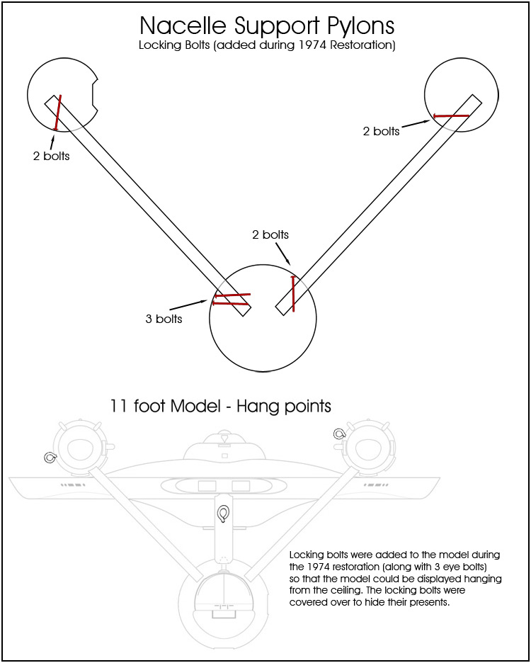
Originally the support pylons slid tightly into place in the secondary hull, and the nacelles slid tightly into place on the support pylons. This tight fit was all that was needed for how the Enterprise was filmed... even early on when it was filmed hanging from a wire (that was anchored in the base of the secondary hull and threaded through a hole in the dorsal's spine).
Just thought I'd share that even though it doesn't directly effect this model.
I also started adding in the additional details to the front nacelle parts.
I meant to share this, but forgot that I had done it. About a week ago I added in the holes on the backside of the dorsal that correspond to where the wires will enter.
One of the things that is important in doing this research is figuring out what was there originally and what was added later. In the case of holes in the model, there are a lot of additional holes seen in these images that weren't originally there when the model was being filmed for TOS.
There are a number of large holes in the secondary hull and nacelles that were added during the 1974 restoration. These holes correspond to locking bolts that anchored the nacelles to the support pylons and the support pylons to the secondary hull. The reason this became a necessity was that the model was going to be displayed hanging from the ceiling. The holes for these bolts were covered and aren't visible while the model is on display.
Originally the support pylons slid tightly into place in the secondary hull, and the nacelles slid tightly into place on the support pylons. This tight fit was all that was needed for how the Enterprise was filmed... even early on when it was filmed hanging from a wire (that was anchored in the base of the secondary hull and threaded through a hole in the dorsal's spine).
Just thought I'd share that even though it doesn't directly effect this model.
Fascinating. I love your research. Your scholarly approach to this stuff is a boon for the rest of us. Thanks for sharing it all!
In fact, I was able to make use of some your research on a project I just finished. Check it out over on TrekBBS:
March 2014 Art Challenge -- Albertese - The Trek BBS
I made my own decals starting with the cleaned up version you had posted on Federation Reference. I made sure to mention you in the thread. Ultimately the N, C, -, 1, and 7 was the only things that were unchanged when I was done, but just the fact that you had already found and cleaned up the original decals was a huge help.
So, yeah, I just wanted to say thanks for your excellent work on this stuff.
--Alex
Shaw
Well-Known Member
So someone had asked how I arrive at some of my measurements. Basically, what type of steps do I use in analyzing (usually visual) data. Honestly, it is a bit of everything when picking stuff apart. But in the last couple weeks I had to work on something that sorta helps illustrate how I work backwards to find a gauge and then work my way forwards applying it.
It is funny, there were some parts of my plans I thought I had addressed back in 2009/2010 that, as it turned out, I hadn't. I think part of the problem is that that was about the time I did my second revision of my 33 inch Enterprise plans, so I remember working on these areas, just on a different model.
One such area was the intercoolers. I needed to start this part because I need to make a mold of it to cast six copies for this model, and I realized I didn't have any solid analysis of it. I also needed to start in on the nacelle support pylons and realized that I needed additional data on those as well. Neither of these parts do I have ideal reference images of (images with the parts next to a ruler), so I started looking for something to use as a gauge for measuring them.
I realized that a good reference source was the x-rays of the model. The model hadn't been fully disassembled for the process, and the nacelle support pylons were still in place in the mosaic of the secondary hull that the Smithsonian had released. While I'm willing to trust an x-ray to give good data, I'm a little skeptical of error creeping in when a series of images are worked together. So I needed something that I could find in the rear secondary hull part of that mosaic that I knew (or could find the dimensions of) to use for making measurements.
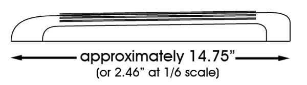
Then a light bulb lit up… or more to the point, was sitting right there in the image. That was most likely a standard light bulb, which means that it is most likely an E26 light socket (26 mm in diameter). Using that information I got approximately 5 inches (4.94 inches) for the width of the nacelle support pylon. I have another image that shows both the nacelle support and the intercooler in the nacelle channel (which is the same length as all the others), and from that I got an approximate length of 14.75 inches (or 2.46 inches at 1/6th scale).
From there I knew the general shape… but something had always bothered me. I knew (because one of the intercoolers was put on backwards) that the part for the 33 inch Enterprise was taller towards the front. I had assumed that the 11 foot model had a uniform height for it's intercoolers, but I wanted to be sure. The first hint that it had the same type of profile as the 33 inch model's came when I saw those parts stacked next to each other in a restoration image, with a pair going in one direction and another pair heading in the other. So yes, they sloped down towards the rear. Now I needed to figure out how much. The grating used on those parts started at the rear with five rows and ended in the front with six, so the height had increased by about 20% over the length of the grating, which helped me figure out the approximate slope.
And that was enough information to at least throw together a drawing that I could use to start building the master part I needed.
That isn't the only way to determine the measurements I needed, and I actually tried a couple other ways to see if any significant errors popped up, but they didn't.
So while I'm more than happy to take some of the larger scale measurements that have been published on faith, I'd still like to go back an work out many of the finer details by my own analysis. I'll add this type of stuff to my notes and I'll most likely redraw the intercoolers a few more times before I decide to finalize them for my plans. But I was able to put enough data together to move forward on both the intercooler and nacelle support pylons for my model.
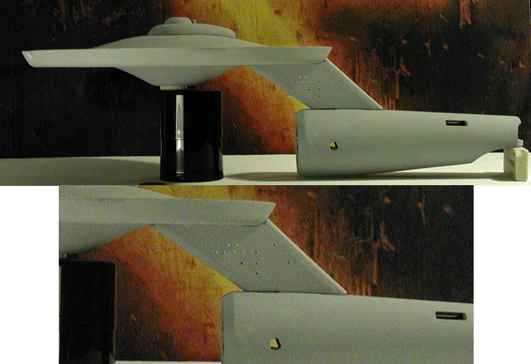
With the drawing in hand, I used it to cut out a number of pieces of sheet styrene and stacked them together to give me the thickness I needed. I then used putty and sanding to get the part rounded off the way I wanted.
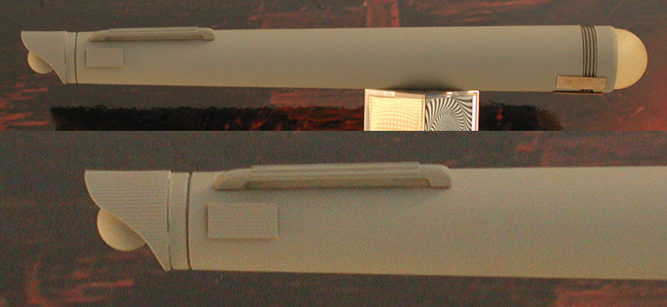
The master is pretty close to being ready to use for making a mold, but I figured I should see how the master looks when in place on the rear of one of the nacelles…
I'm pretty happy with the results. Hopefully I can make six copies that work as nicely. But more importantly, this helped fill in a gap in my research I hadn't realized I had before I started working on this part.
It is funny, there were some parts of my plans I thought I had addressed back in 2009/2010 that, as it turned out, I hadn't. I think part of the problem is that that was about the time I did my second revision of my 33 inch Enterprise plans, so I remember working on these areas, just on a different model.
One such area was the intercoolers. I needed to start this part because I need to make a mold of it to cast six copies for this model, and I realized I didn't have any solid analysis of it. I also needed to start in on the nacelle support pylons and realized that I needed additional data on those as well. Neither of these parts do I have ideal reference images of (images with the parts next to a ruler), so I started looking for something to use as a gauge for measuring them.
I realized that a good reference source was the x-rays of the model. The model hadn't been fully disassembled for the process, and the nacelle support pylons were still in place in the mosaic of the secondary hull that the Smithsonian had released. While I'm willing to trust an x-ray to give good data, I'm a little skeptical of error creeping in when a series of images are worked together. So I needed something that I could find in the rear secondary hull part of that mosaic that I knew (or could find the dimensions of) to use for making measurements.
Then a light bulb lit up… or more to the point, was sitting right there in the image. That was most likely a standard light bulb, which means that it is most likely an E26 light socket (26 mm in diameter). Using that information I got approximately 5 inches (4.94 inches) for the width of the nacelle support pylon. I have another image that shows both the nacelle support and the intercooler in the nacelle channel (which is the same length as all the others), and from that I got an approximate length of 14.75 inches (or 2.46 inches at 1/6th scale).
From there I knew the general shape… but something had always bothered me. I knew (because one of the intercoolers was put on backwards) that the part for the 33 inch Enterprise was taller towards the front. I had assumed that the 11 foot model had a uniform height for it's intercoolers, but I wanted to be sure. The first hint that it had the same type of profile as the 33 inch model's came when I saw those parts stacked next to each other in a restoration image, with a pair going in one direction and another pair heading in the other. So yes, they sloped down towards the rear. Now I needed to figure out how much. The grating used on those parts started at the rear with five rows and ended in the front with six, so the height had increased by about 20% over the length of the grating, which helped me figure out the approximate slope.
And that was enough information to at least throw together a drawing that I could use to start building the master part I needed.
That isn't the only way to determine the measurements I needed, and I actually tried a couple other ways to see if any significant errors popped up, but they didn't.
So while I'm more than happy to take some of the larger scale measurements that have been published on faith, I'd still like to go back an work out many of the finer details by my own analysis. I'll add this type of stuff to my notes and I'll most likely redraw the intercoolers a few more times before I decide to finalize them for my plans. But I was able to put enough data together to move forward on both the intercooler and nacelle support pylons for my model.
With the drawing in hand, I used it to cut out a number of pieces of sheet styrene and stacked them together to give me the thickness I needed. I then used putty and sanding to get the part rounded off the way I wanted.
The master is pretty close to being ready to use for making a mold, but I figured I should see how the master looks when in place on the rear of one of the nacelles…
I'm pretty happy with the results. Hopefully I can make six copies that work as nicely. But more importantly, this helped fill in a gap in my research I hadn't realized I had before I started working on this part.
Shaw
Well-Known Member
Small update...
I'm happy enough with where the intercooler master is at to make a mold of it. As with most of my parts, this is more like reaching a point on an illustration and hitting save before going forward. It isn't done or perfect, but I'd rather have this as a starting point than try doing more and messing it up.
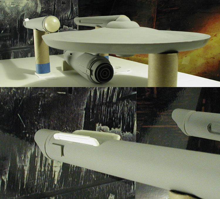
Here is a couple more shots with the nacelle assembled with other parts. Both nacelle bodies need to be shorten by a little less than a quarter inch in the front, so I'm not too worried about the front edge not being smooth yet.
And I figured as long as I took the time to put one of the nacelles together, I might as well put all the major parts together to see how the model is doing. This is actually the first time I've done this with this model, so it was something I was curious about.
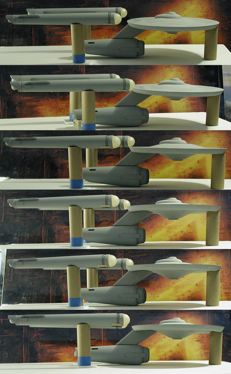
It still has plenty of rough spots and still needs a lot of work, but I think I'm headed in the right direction.
I'm happy enough with where the intercooler master is at to make a mold of it. As with most of my parts, this is more like reaching a point on an illustration and hitting save before going forward. It isn't done or perfect, but I'd rather have this as a starting point than try doing more and messing it up.
Here is a couple more shots with the nacelle assembled with other parts. Both nacelle bodies need to be shorten by a little less than a quarter inch in the front, so I'm not too worried about the front edge not being smooth yet.
And I figured as long as I took the time to put one of the nacelles together, I might as well put all the major parts together to see how the model is doing. This is actually the first time I've done this with this model, so it was something I was curious about.
It still has plenty of rough spots and still needs a lot of work, but I think I'm headed in the right direction.
Shaw
Well-Known Member
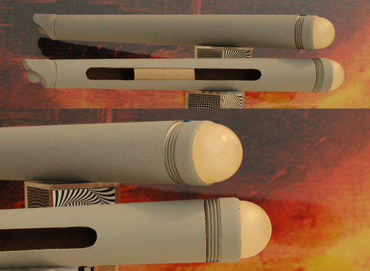
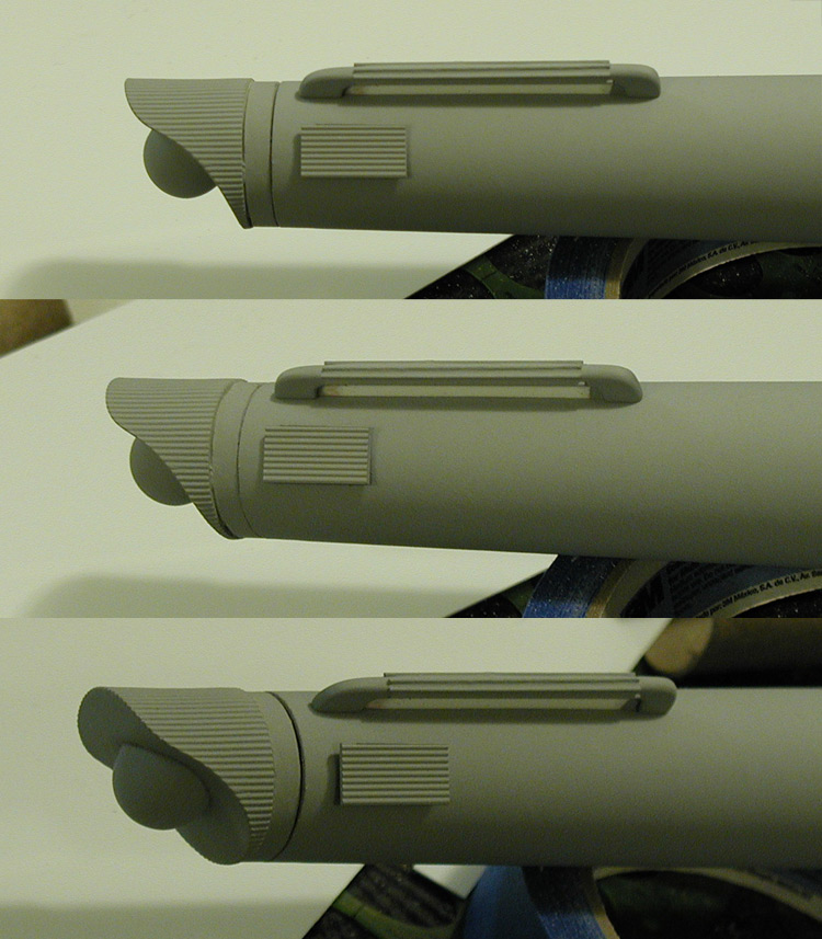
So I made the mold for the intercooler and I've pulled two of them (out of the six I'll need) so far. I sanded down the bottoms, but haven't done anything else yet... here is how they look just set in place.
I made note of any differences in the ribbing on the original model so I can modify the final parts I pull to match. In the illustration below we are looking at them from the top with all of them heading to the right (I point this out as the starboard side inboard channel intercooler is upside-down from how it would be on the actual nacelle)...
I'm guessing that this is how the ribbing was originally added to the model for the second pilot as any thought of filming too far past the model's center line was removed by the addition of wiring to the back side's surface.
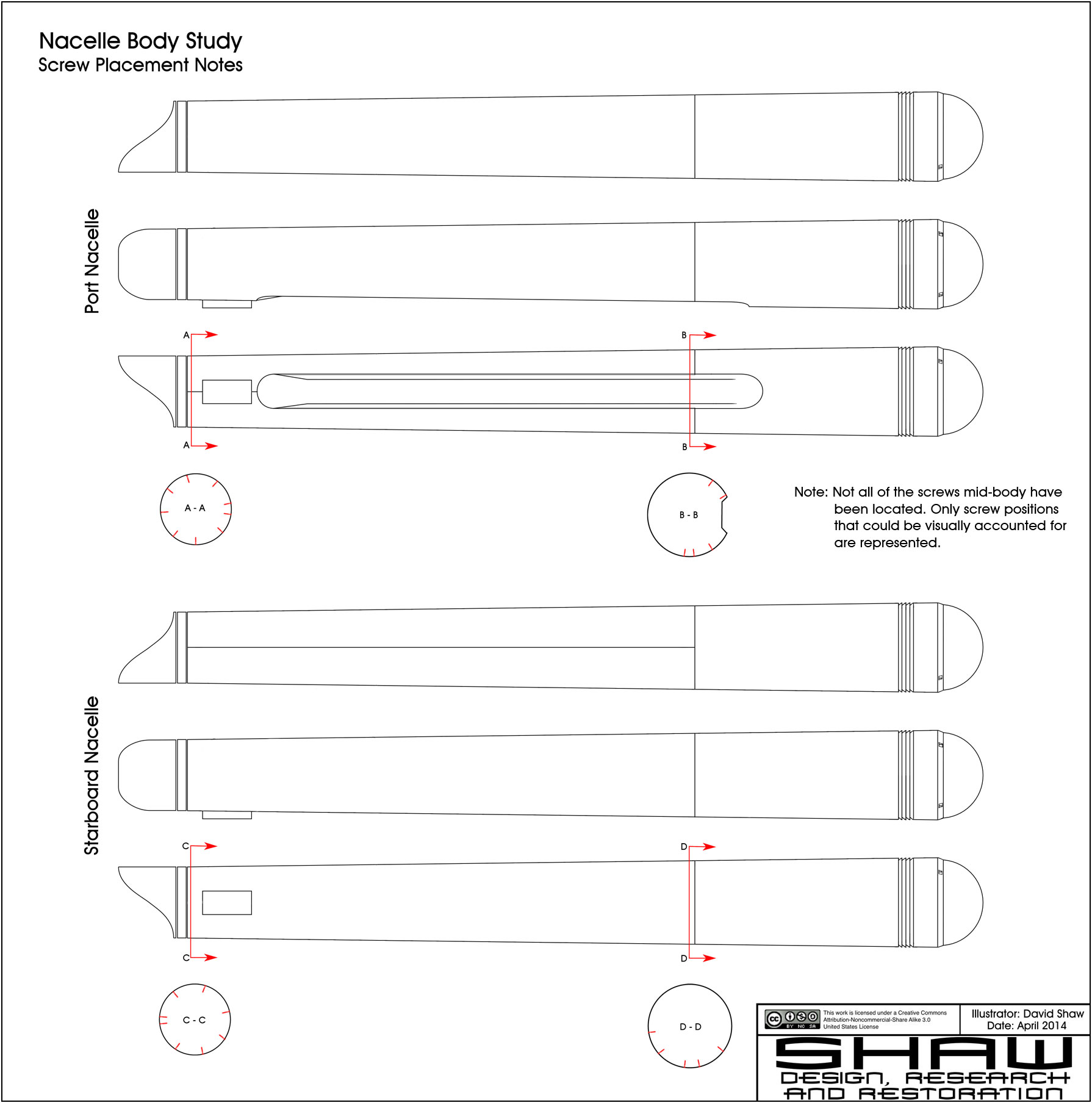
Here are my notes on the approximate screw positions on the nacelles of the original model. The reason this isn't going to matter with this model is that the screws were well hidden on the model while being used for filming during the original series. They started showing up on the model after it was put on display by the Smithsonian and for some reason no attempt was made to cover the rear screws during the last restoration of the model.
Like figuring out the plank arrangement for the secondary hull, this is information collected for my plans, not this model... but I figured I'd share this anyways.
I made note of any differences in the ribbing on the original model so I can modify the final parts I pull to match. In the illustration below we are looking at them from the top with all of them heading to the right (I point this out as the starboard side inboard channel intercooler is upside-down from how it would be on the actual nacelle)...
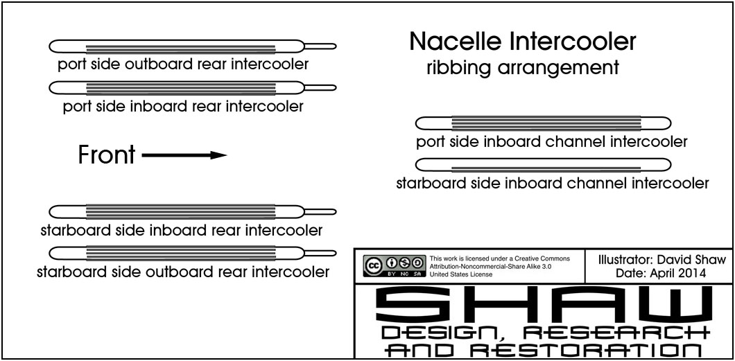
I'm guessing that this is how the ribbing was originally added to the model for the second pilot as any thought of filming too far past the model's center line was removed by the addition of wiring to the back side's surface.
Here are my notes on the approximate screw positions on the nacelles of the original model. The reason this isn't going to matter with this model is that the screws were well hidden on the model while being used for filming during the original series. They started showing up on the model after it was put on display by the Smithsonian and for some reason no attempt was made to cover the rear screws during the last restoration of the model.
Like figuring out the plank arrangement for the secondary hull, this is information collected for my plans, not this model... but I figured I'd share this anyways.
Shaw
Well-Known Member
Small update...
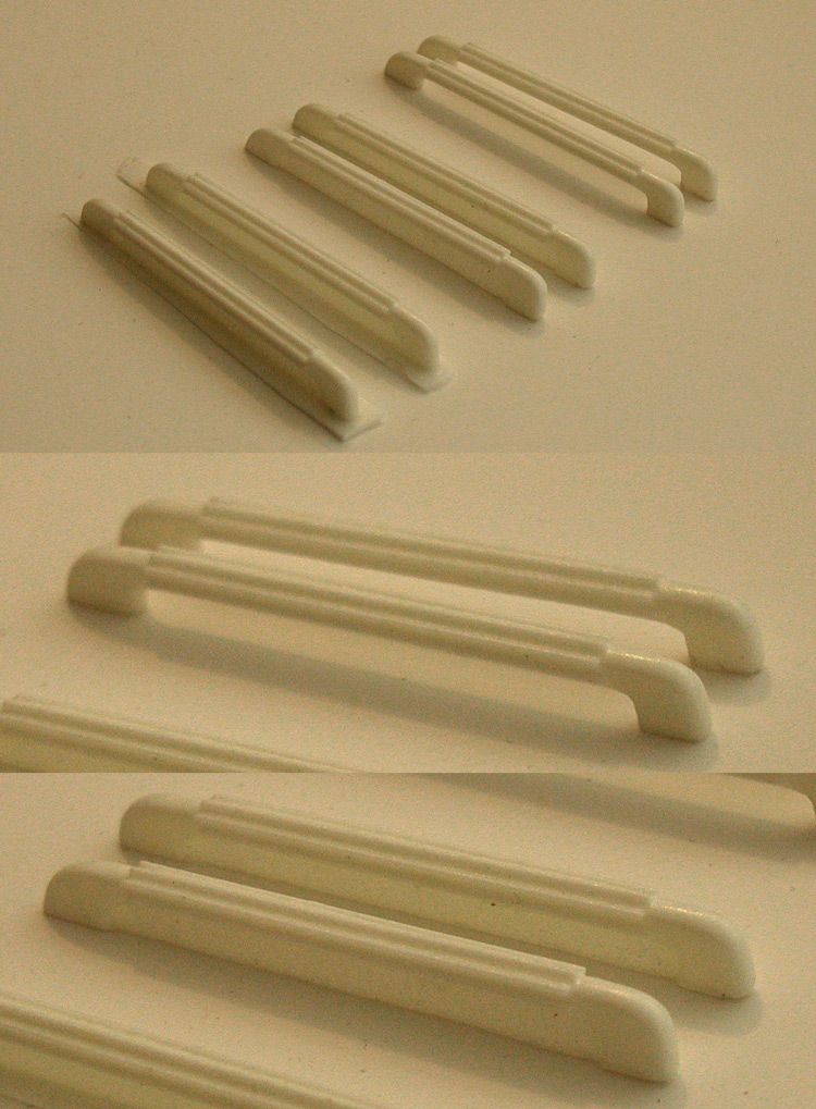
I pulled all the intercoolers. I removed the flash from four of them, and the screen from two of them (that will be used for the inboard ones). Otherwise, they haven't had any other work done on them.
Here is how they look...
If I have any time this weekend I'll most likely start the impulse engines. I don't really know why I haven't done this part yet, the last time I did it it was pretty straight forward.
Similar threads
- Replies
- 1
- Views
- 284