One-Sixth Studio Scale TOS Enterprise

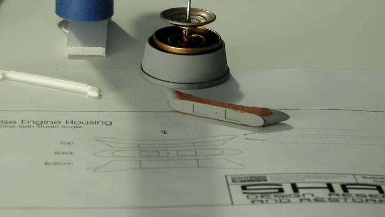
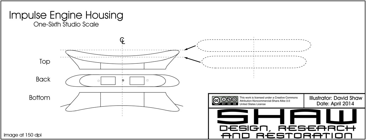
So I went back through all my reference images and remeasured everything for the impulse engine housing. I think this is pretty close to the studio model's part… though I might be off a bit on how it intersects with the primary hull rim, but I don't need that aspect right now.


I noted the placement of the screws that hold the part to the primary hull, though they shouldn't be visible as they were filled in on the studio model during production. I didn't include the fabric (other than the boundary lines) because I'm working on the main shape of the part first.

Now to see if I can build that.
 
Okay, after a long delay (because of work commitments) I have finally made some real progress on the impulse engines.

1701-11-048.jpg

I finished up on the major aspects today. Here are some shots of it in place (held there by a single piece of tape)...

1701-11-049.jpg

I need to let it finish drying/curing for a while and then I'll hit it with a final coat of primer.

Also in that first picture is the deflector assembly. Those are the final rings, I ended up making a mold of the original ones in case I decide to build this model again in the future. And because I painted the rings, I wanted to try out some ideas on the deflector dish... but I'm still working on that part, so the one in the picture is a stand-in. Basically it is painted the same color as the rings and then I added weathering to it (using silver and steal). I did it in a number of steps to see how far was too far, so on the final part I will stop before I get to this point... but I was happy with the effect I got.

Here is what I'm working from for the deflector dish...


The engraving of the outer ring has been a pain.
 
Thanks!


So I felt like I wanted to work on something a little different today, so I started in on the master for the name plate.

1701-11-050.jpg

It is still a work in progress, but I think it shows what I'm aiming for. The final parts will be painted either brass or copper.
 
I threw together a couple diagrams from some of my notes and figured I'd add them to this thread (as this is what this study model is helping me research)...


The second diagram mainly shows the planking on the secondary hull. These were glued together and the stress from standing assembled for decades has caused some separation between them on the original model. I also included a lot of the known holes that currently exist on the model... including the ones added in 1974 and used for bolts to lock the model together (here are those modifications again).

1701-11-study_004.jpg

Some of these bolt holes have started to become visible as the putty used to fill them has started to separate from the surrounding wood.

I figured with a ton of new photos of the model in better lighting than when it was on display, these references might be helpful (or at least interesting) to some of you guys.
 
This thread is more than 9 years old.

Your message may be considered spam for the following reasons:

  1. This thread hasn't been active in some time. A new post in this thread might not contribute constructively to this discussion after so long.
If you wish to reply despite these issues, check the box below before replying.
Be aware that malicious compliance may result in more severe penalties.
Back
Top