Batman 1989 Vault weapons display

gregday

Sr Member
RPF PREMIUM MEMBER
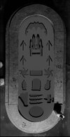
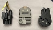
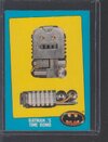
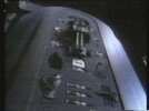
I have a pretty much complete collection of Batman 89 gadgets, and for years I’ve been trying to think of the proper way to display them. I don’t have the space to build an entire Batsuit vault, nor any plans to build an 89 suit to go in one. But I always loved the way the gadgets were laid out on the inside of the door.

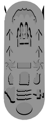
I started by designing the foam layout and roughing out how much space I'll need. I have more work to do to finalize the foam before sending it for production, so more on that layer.

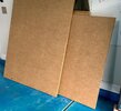
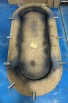
Step 1 this past weekend was deciding how I'm going to build this and rough out the material. At first I thought wood, but I knew I'd have to make a lot of curved cuts, and my space for tools is limited. I'm working entirely with handheld power tools, and I thought MDF would be easier to work with, and be easier to shape the details on. So I got some 8'x4' panels and started roughing out the shapes.

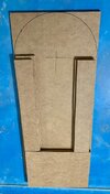
Rather than going for an exact reproduction of the door, I'm making it a little shorter and possibly a bit narrower. I decided on a foam area of 44" tall and 15" wide, and then building the solid door around that. So accounting for the concentric ring layers, that gives me a total door height of 55" x 26".

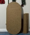
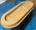
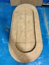
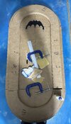
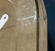
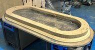
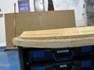
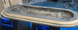
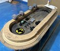
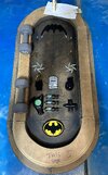
The back wall of the door, what I'm calling "Tier 3" is one single solid piece of 0.75" MDF with the ends radiused to create the pill shape. I used a screw at the circle center point with a pen tied to a string to draw the curves. After seeing how Tier 3 came out, I felt good enough to measure and start creating Tier 2.

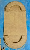
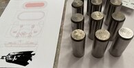
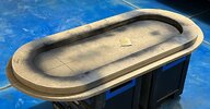
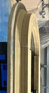
Tier 2 will really be subdivided into upper and lower sections, with the lower section (Tier 2B) having a 45º chamfer down to Tier 3, and the upper section (Tier 2A) a straight 90º cut, which will house the locking bolts. Tier 2 in all will be 3" thick (4 MDF layers), and the bolts will be installed into the straight side of 2A. I went ahead and glued the two layers for 2A together and the layers for 2B together. I then felt a bit sheepish as only then did I realized that 2A, sitting on top of the chamfered 2B layer, will actually need to be a little smaller than 2B. Oops. No worries though, nothing to have to re-do, I'll just need to trim it a bit. I'm going to wait until after 2B is done, and probably glued down to Tier 3 before making that trim. Right now I'm waiting on the correct router bits to arrive before I can make that cut.

After Tier 2 is all done, I will cut the smallest, top tier: Tier 3, which will be the most forward layer and be made of just one 0.75" layer, also with a 45º chamfer.

After that, tons of sanding to smooth out those jigsaw cuts, Bondo for the gaps and seams, more and more sanding, and then I'll resin coat the whole thing for a nice, even, protective coat that will tie it all together. Then paint, then installing the lock bolts.

I'll use this thread as my build log and welcome any tips if anyone has them.

I am leaving open the possibility of putting some outer door details on the back, but I don't want it to stick out too much. I might even just paint on the hinge and wheel details in 2D just for an effect.
 

Attachments

  • 0.jpg
    0.jpg
    162.1 KB · Views: 89
  • 0-1.jpg
    0-1.jpg
    123.8 KB · Views: 69
  • 0-2.jpg
    0-2.jpg
    152.4 KB · Views: 78
  • 0-3.jpg
    0-3.jpg
    135.2 KB · Views: 72
  • 0-4.jpg
    0-4.jpg
    137.5 KB · Views: 72
  • 0-5.jpg
    0-5.jpg
    207.9 KB · Views: 77
Here's my foam layout. I tried to recreate the film door best I could while not going crazy on the height, and I've never seen anything lower than the smoke capsules in any screen grabs, so I don't know if there's anything below that. I also have 1 non-screen-accurate addition I'm making. I have this incredibly cool metal construction chest emblem I want to include, and will make a nice end cap at the bottom. I may tweak some of the shape sizes and move them around a couple pixels, but this is pretty much it. I will wait until the door interior is actually done before taking precise measurements and ordering the foam. I'm using mycasebuilder.com to design and purchase it. Ignore the weird shear planes on the corners here, it's just an artifact of the templated negatives I had to use to get rounded ends.
 

Attachments

  • Screenshot 2023-04-03 at 12.06.41 PM.png
    Screenshot 2023-04-03 at 12.06.41 PM.png
    262.1 KB · Views: 107
Getting a bit ahead of myself, but I wanted to go ahead and get these early. I like having components that are pretty much ready to go to help me stay motivated and focused.

These locking bolts are 3”x1.25” steel (thanks McMaster-Carr). They need a bit of polishing up but they look and feel perfect.
 

Attachments

  • IMG_2697.jpeg
    IMG_2697.jpeg
    1.3 MB · Views: 81
Started gluing down some of the layers to the back wall last night, and paused for an overhead shot. Then dropped my foam 3D render on top and desaturated the colors to get an idea how the proportions will feel.

The rest of this week is going to be getting a more precise fit and softening the edges. Hopefully the chamfers I can cut this weekend.
 

Attachments

  • IMG_2762.jpeg
    IMG_2762.jpeg
    1.5 MB · Views: 97
  • Screenshot 2023-04-04 at 10.45.35 AM.jpeg
    Screenshot 2023-04-04 at 10.45.35 AM.jpeg
    352.1 KB · Views: 101
Glued down the first layer of Tier 2 and filled the seams with putty. Hit those spots with a little paint to help verify how flush they are. Of course, this is mostly for structure, as the next layer of Tier 2 will cover the top side.

Also laid out some of my lock bolts to make sure the proportions feel right. Not actually showing the correct height or depth of where they will be installed, just roughly where they will lie along the X-axis.
 

Attachments

  • IMG_2772.jpeg
    IMG_2772.jpeg
    371.2 KB · Views: 72
  • IMG_2779.jpeg
    IMG_2779.jpeg
    386.6 KB · Views: 69
  • IMG_2778.jpeg
    IMG_2778.jpeg
    1.3 MB · Views: 67
I am so jealous!! I've want to do this exact thing since I saw the movie on my 16th birthday. I look forward to more progress.
 
Parts for the Time Bomb arrived today. I already had a pretty crummy solid printed plastic one, and then I found a model for one assembled from parts. I splurged and had all the parts printed in steel and brass on Shapeways. Not cheap!

At first glance I was gutted because it’s much smaller than my plastic one, but after putting it next to the Paragon FX grapnel, I actually kind of like this scale!

It took a little bit to figure out how it assembles because strangely the design is mirrored from how it ought to be. Don’t know how I missed that before ordering. But for an obscure prop that was never featured on screen, I am totally happy with it. The weight on this thing is amazing and finishing it is going to be so fun.
 

Attachments

  • IMG_2796.jpeg
    IMG_2796.jpeg
    1.1 MB · Views: 95
Now is a good time to point out that I hate the way the time bomb is displayed in the door. The design clearly looks better with the cylinder greeblies on top and the rounded end in the palm. There’s even ridges on the end for gripping! Alas, the bomb is clearly seen in the door greeblies down, and the Batman collectible trading cards from 1989 confirm this orientation.
 

Attachments

  • IMG_2797.jpeg
    IMG_2797.jpeg
    155.7 KB · Views: 127
Very cool piece! I'm looking forward to see how you finish it! That trading card is cool too - I've not seen it. The "TM" inserted before the possessive "S" cracks me up.
 
Last edited:
After handling the new model and studying my reference more closely, I have some thoughts on the bomb’s orientation.

The 3 main sources are the trading card, a very brightened HD screen grab with Michael Gough next to the vault, and a behind-the-scenes shot taken from an upward angle.

Initially I thought the bomb was oriented with the cylinder greeblies up because it just looked right to me, and the oversized model I was using made it more ergonomic to hold with the rounded end in the palm. Now I see how the smaller (and I believe more correct) size works the other way, and I see there are 2 thumb buttons on the round end that appear to be used for stepping through the timer.

And in the behind-the-scenes footage, it’s oriented greeblies down, which matches the trading card.

However, in the actual released movie, looking closely, it looks like they put it in in the door upside down — it’s greeblies up! Which means the foam cutout shape doesn’t match how they stuck it in there.

So… summarizing…

- At first glance I’d say the prop looks better greeblies up.

- On closer inspection, I see how the design can be intended greeblies down.

- The trading card reference and behind-the-scenes footage clearly shows it greeblies down as well, which is how they cut the foam for it.

- Then when it came to filming the actual movie that got released, they flipped it back the other way, which doesn’t match the hole they made for it.

So, given all this and considering the prop was never otherwise used or seen on screen, my conclusion is that I can orient it whichever way I want and it will be correct. I’m inclined to go with greeblies down, since the top curve of the bomb kind of repeats the symmetry of the Batarang's curve as well the curve of the vault door itself.
 

Attachments

  • VaultAlfred2.jpg
    VaultAlfred2.jpg
    35.4 KB · Views: 146
  • IMG_2606.JPG
    IMG_2606.JPG
    30.3 KB · Views: 154
Last edited:
Not likely. The cutout in the vault door is designed for that orientation, and that’s how it is in the behind the scenes. In the film screen grab you can see the bomb is greeblies-up but it doesn’t match the cutout.
 
The trading card image also appears to have just the hint of the "1" in the two left slots of the "timer" digit counter, indicating the greeblies would be on the bottom, IMHO.
 
The old behind the scenes image of the propmaster holding it and pushing the button shows him holding it button up. The numbers are oriented that way too.
 

Attachments

  • Screen Shot 2023-04-06 at 8.13.39 PM.png
    Screen Shot 2023-04-06 at 8.13.39 PM.png
    1.9 MB · Views: 99
The old behind the scenes image of the propmaster holding it and pushing the button shows him holding it button up. The numbers are oriented that way too.
Well that settles it. Interesting that the timer actually seems functional. And that the center button moves also. They just had it in the door wrong for the movie.
 
My guess is that the body of it is actually some sort of found object. With some parts added to make the prop.
 
Never really used a plunge router before, so today's goal went really well. Tier 2B has a nice 45º chamfer, and Tier 2A is trimmed appropriately to sit on top, and glue is setting now.

If I get time tomorrow, the next steps are to cut the narrowest, topmost layer, route it's chamfer, and glue in place. Lots of filler and sanding to get everything nice and smooth, and then cut out the holes for the locking deadbolts.

I'll be experimenting with the epoxy resin and paint throughout this week, and barring any big issues, I plan to begin coating by next weekend.
 

Attachments

  • IMG_2877.jpeg
    IMG_2877.jpeg
    846.8 KB · Views: 68
  • IMG_2875.jpeg
    IMG_2875.jpeg
    269.7 KB · Views: 68
  • IMG_2873.jpeg
    IMG_2873.jpeg
    1.8 MB · Views: 57
  • IMG_2867.jpeg
    IMG_2867.jpeg
    672.4 KB · Views: 60
First test with some items and it’s starting to look like a Thing. Don’t give me too much crap for using dumbbells to help the glue set. I didn’t have the right size clamps :p

I’m not happy with the right side straight piece, so I’ll remake that tomorrow. Then cut and route Tier 3 pieces, glue/fill/sand, and (fingers crossed) be able to bore out the deadbolt holes and be done with the MDF work this weekend.
 

Attachments

  • IMG_2880.jpeg
    IMG_2880.jpeg
    1.5 MB · Views: 126
  • IMG_2879.jpeg
    IMG_2879.jpeg
    1.4 MB · Views: 143

Your message may be considered spam for the following reasons:

If you wish to reply despite these issues, check the box below before replying.
Be aware that malicious compliance may result in more severe penalties.
Back
Top