It looks like you are onto something here.So you can change the blinking rate by changing the timing resistor value, the capacitor or the supply voltage. I think what we see in the cave scene is caused by battery sag because from what I remember reading about the 555 - the early versions were somewhat power hungry and that the old zinc batteries tend to drop voltage under load more than the modern ones (some guitar players believe this battery response caused their fuzzes to sound so good back in the day, compared to when they use them with power supply or modern battery).
Or he might be shorting the timing resistor with the tool (or if there was some resistor or diode on the power path) or a combination of all that.
Here's a link to a quick video I made to demonstrate it (sorry for the bad quality)
(I added a couple of diodes between the battery and the 555 blinking circuit to cause voltage drop and I'm shorting them to cause the voltage to temporarily jump up)202307161327.mp4
drive.google.com
You are using an out of date browser. It may not display this or other websites correctly.
You should upgrade or use an alternative browser.
You should upgrade or use an alternative browser.
Thin Neck Thanksgiving- Luke Cave Found Parts Revealed!
- Thread starter BRRogers
- Start date
Poikilotherm
Sr Member
If I understand you correctly, you just need to change the resistor value until you get the correct flashing rate.
Good to see that a homemade circuit can fit inside.
Would you be able to post a schematic of your circuit?

Red led
Green led
NE555
10K resistors
100K resistors
2.2uf capacitors
10nf capacitors
Micro switch
4.5V button cell
It seems to work well!So you can change the blinking rate by changing the timing resistor value, the capacitor or the supply voltage. I think what we see in the cave scene is caused by battery sag because from what I remember reading about the 555 - the early versions were somewhat power hungry and that the old zinc batteries tend to drop voltage under load more than the modern ones (some guitar players believe this battery response caused their fuzzes to sound so good back in the day, compared to when they use them with power supply or modern battery).
Or he might be shorting the timing resistor with the tool (or if there was some resistor or diode on the power path) or a combination of all that.
Here's a link to a quick video I made to demonstrate it (sorry for the bad quality)
(I added a couple of diodes between the battery and the 555 blinking circuit to cause voltage drop and I'm shorting them to cause the voltage to temporarily jump up)202307161327.mp4
But given the button switches I see hidden in the overlay plate in that picture Bryan posted, including the dampened popping sound when the tool leaves that position in the cave scene, I'd personally stick with the 1SX1-T.But after using the Ne555 I do think that the Ne555 gives a much better result for LEDs than the regular adaptive Led flicker. At the very least it is certain that the Ne555 can be put into a Hero control box to work for it.
Last edited:
Those sounds effects could be recorded separately from the video and could be mixed from random stuff that someone is messing with in the sound studio - just like the lightsaber ignition sound. At least for me the sounds don't really match what I'm seeing. For example the initial power-on with the slide switch makes the kind of sound like it's something spring loaded. Also the sound the clamp card makes when he closes the control box is quite weird... I mean there's probably a switch to toggle between the red/green leds, but what we hear is not necessary what is actually happening there.
Poikilotherm
Sr Member
I've amplified the sound, and yes other sounds were obviously added behind the scenes, but at least one of them verified that it was the sound of a switch bouncing, or at least that's what would come up when I mimicked the same action of the cave. Of course this is just my understanding as this sound always comes up when I switch back to the blinking green led. popping~~~~~~Those sounds effects could be recorded separately from the video and could be mixed from random stuff that someone is messing with in the sound studio - just like the lightsaber ignition sound. At least for me the sounds don't really match what I'm seeing. For example the initial power-on with the slide switch makes the kind of sound like it's something spring loaded. Also the sound the clamp card makes when he closes the control box is quite weird... I mean there's probably a switch to toggle between the red/green leds, but what we hear is not necessary what is actually happening there.
I also recorded a couple of my cave video reenactments with fast playback as well as slow playback with the original sound. and mixed the cave sound with my sound, but the original switch trigger sound has been cleared so as to use my trigger sound as well as the PCB card slide sound.
Last edited:
This is the standard schematic:

In my experience there's no real need for C2 for our purpose and can be omitted to save some space in the control box.
connect the momentary switch to 3 then the + of the leds to it and the - of the leds to ground. Might need to add some small resistors in series with them to prevent burning them , depending on what voltage you use.
C1 and R2 control the blinking rate. You can change them to taste (bigger values = slower blinking) also R1 but it only affects the charging time of C1
So far I was not really interested to reproduce this temporary faster blinking rate. But now I got curious if I can do it with some minimal components that will still fit in the control box.
So as far as I can tell when watching the cave scene - it blinks faster for a second or so when it is powered on and then slows down to the normal rate. Same happens when led colors are switched - when the red led turns on it first blinks little faster and slows down and then when it goes back to green - again it blinks faster for a short period and then slows down. Finally, it looks like when he clicks or touches with the tool whatever changes the led to red - he keeps the tool pressed all the time, so the rate slows down on it's own.
I choose this time to play with the control pin to vary the speed, but the same approach can be used to run in parallel to the timing resistor R2 or to the power supply like in my previous test.
So as fist step I wanted to make it start faster when powered on, but then slow down on its own after a while. From what I understood by playing with the control pin you can only slow the rate but cannot make it faster than what is setup by R2 and C1 pair. So in this case R2 and C1 should be selected to blink at the faster rate and then use the pin to slow it down to the "normal" rate.
This is what I came up with :

So what's added is the resistor R4 connected between pin 5 and + and the value is selected so when connected it slows down the rate to what looks good. Then there's a transistor that acts as a gate and essentially connects R4 to +. However this is delayed a little until C2 is charged enough. In summary: C1 and R2 set the fast rate; R4 the slow rate; R3 and C2 the time from power on until the rate slows down. R5 is there just so C2 has some way to discharge when the power is off (otherwise the whole thing will work only the fist time it powers on).
Then I started looking how to speed up when by pressing a momentary switch and then slow down when it is released. This pressed together with another momentary switch that swaps the leds (or maybe using a single dpdt switch) will get pretty close to what is seen on screen (but not perfect).
Here is what looks with the switch:

It just shorts C2 to ground to drain it instantly and maybe is not the most elegant way to do it but it worked. I prototyped it on the breadboard and tried to record a video, but my phone camera is messed up and hunts for focus all the time so it turned out pretty annoying to look at. But if anyone is interested I can share it. I didn't try to fit this in the control box, but I think it should still fit (if the battery is external though).
So the only problem with this is if you press the two switches together (the one to change the color and the one to change the rate) and keep them pushed like it is in the cave scene - the red led will start at faster rate but will not slow down. Then when you release - the green will start at the fast rate but then slow down as desired.
In my own build I don't use a switch for changing the color but just short 2 traces with the tool, so placing a switch below that will probably allow me to press on the traces and pushing the switch at the same time - then slide the tool a little so it is not shorting the traces anymore but still presses the switch, then slide it back over the trace then release to get both the color and the rate change as in the movie - but is far from perfect solution.
I think if one of those switches that are open on one side and closed on the other is used can make this work better but I don't have one to try.
But my idea is to add another pair of resistor and capacitor R6 and C3 (same values as R5 and C2) and use the switch to toggle between the pairs. This way when you press the switch the loaded capacitor will be replaced with empty one so the rate will speed up; then slow down again when the empty capacitor is charged enough - while you still hold the switch pressed (meanwhile the disconnected loaded capacitor will discharge through its resistor). Then when the switch is released the capacitors again will be swapped and the whole thing will repeat.
Something like this:

I've not tried this though as I didn't have the extra components needed. And I don't think I can fit all of it in the control box if I have to, but in my FX build I can move some of it into the main body where I have plenty of space.
So as far as I can tell when watching the cave scene - it blinks faster for a second or so when it is powered on and then slows down to the normal rate. Same happens when led colors are switched - when the red led turns on it first blinks little faster and slows down and then when it goes back to green - again it blinks faster for a short period and then slows down. Finally, it looks like when he clicks or touches with the tool whatever changes the led to red - he keeps the tool pressed all the time, so the rate slows down on it's own.
I choose this time to play with the control pin to vary the speed, but the same approach can be used to run in parallel to the timing resistor R2 or to the power supply like in my previous test.
So as fist step I wanted to make it start faster when powered on, but then slow down on its own after a while. From what I understood by playing with the control pin you can only slow the rate but cannot make it faster than what is setup by R2 and C1 pair. So in this case R2 and C1 should be selected to blink at the faster rate and then use the pin to slow it down to the "normal" rate.
This is what I came up with :
So what's added is the resistor R4 connected between pin 5 and + and the value is selected so when connected it slows down the rate to what looks good. Then there's a transistor that acts as a gate and essentially connects R4 to +. However this is delayed a little until C2 is charged enough. In summary: C1 and R2 set the fast rate; R4 the slow rate; R3 and C2 the time from power on until the rate slows down. R5 is there just so C2 has some way to discharge when the power is off (otherwise the whole thing will work only the fist time it powers on).
Then I started looking how to speed up when by pressing a momentary switch and then slow down when it is released. This pressed together with another momentary switch that swaps the leds (or maybe using a single dpdt switch) will get pretty close to what is seen on screen (but not perfect).
Here is what looks with the switch:
It just shorts C2 to ground to drain it instantly and maybe is not the most elegant way to do it but it worked. I prototyped it on the breadboard and tried to record a video, but my phone camera is messed up and hunts for focus all the time so it turned out pretty annoying to look at. But if anyone is interested I can share it. I didn't try to fit this in the control box, but I think it should still fit (if the battery is external though).
So the only problem with this is if you press the two switches together (the one to change the color and the one to change the rate) and keep them pushed like it is in the cave scene - the red led will start at faster rate but will not slow down. Then when you release - the green will start at the fast rate but then slow down as desired.
In my own build I don't use a switch for changing the color but just short 2 traces with the tool, so placing a switch below that will probably allow me to press on the traces and pushing the switch at the same time - then slide the tool a little so it is not shorting the traces anymore but still presses the switch, then slide it back over the trace then release to get both the color and the rate change as in the movie - but is far from perfect solution.
I think if one of those switches that are open on one side and closed on the other is used can make this work better but I don't have one to try.
But my idea is to add another pair of resistor and capacitor R6 and C3 (same values as R5 and C2) and use the switch to toggle between the pairs. This way when you press the switch the loaded capacitor will be replaced with empty one so the rate will speed up; then slow down again when the empty capacitor is charged enough - while you still hold the switch pressed (meanwhile the disconnected loaded capacitor will discharge through its resistor). Then when the switch is released the capacitors again will be swapped and the whole thing will repeat.
Something like this:
I've not tried this though as I didn't have the extra components needed. And I don't think I can fit all of it in the control box if I have to, but in my FX build I can move some of it into the main body where I have plenty of space.
Last edited:
Poikilotherm
Sr Member
Good lord you people are smart, this all went over my head.
All I have to add, I think Poikilotherm mentioned they may have switched the clicks from the SX1T because the loudest is first on the real switch and it’s the second in the video? Something like that
All I have to add, I think Poikilotherm mentioned they may have switched the clicks from the SX1T because the loudest is first on the real switch and it’s the second in the video? Something like that
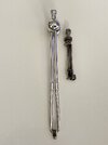
A litlte stressful cutting off that flange, but it turned out very well and I now have an all vintage cave tool. Pictured with a painted lineage hero casting.

CopperRevan
Master Member
Awesome find! Out of curiosity does the vintage matrix have a dimple centered on top of it?I was lucky enough to find a 152 and a vintage matrix retainer. I’m not sure of its age, but it looks quite old.
Awesome find! Out of curiosity does the vintage matrix have a dimple centered on top of it?
Unfortunately no, it’s just a flat top.
The antique ones more likely had manually turned details and variation than any post war counterparts- the original in question could very possibly had a concave indent when the thumbscrew was parted off depending on the machine operator (this part was almost certainly PRE WWI)
I just threw all that crap away…. I must have had 30 bottles I trashedDid anyone with a 152 happen to take photos of the bottle and atomizer over a white background?… Looking for clear shots on the white background of unaltered pieces for our friends at parts of Star Wars. Feel free to PM me.
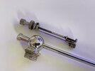
OK, so I got a pair of atomzers and from the picture it looked like they are 2 identical 152. However, when they arrived one is indeed 152, but the other turns out is 215 ...
So there are some diffrences, but given that I was confused they are the same from a relatively decend quality picture
inevitably a question comes up: Do we have enoguh evidence from the deleted scene footage to say 152 is 100% the correct one? Or could it be some other model like the one I stumbled upon?

From what I can make out I sitll lean towards the 152 between the two - because of the part where the rubber tube should attach looks more rectangular to me in the deleted scene.
So there are some diffrences, but given that I was confused they are the same from a relatively decend quality picture
inevitably a question comes up: Do we have enoguh evidence from the deleted scene footage to say 152 is 100% the correct one? Or could it be some other model like the one I stumbled upon?
From what I can make out I sitll lean towards the 152 between the two - because of the part where the rubber tube should attach looks more rectangular to me in the deleted scene.
Last edited:
We know it’s the 152 based on the connection point for the dental matrixOK, so I got a pair of atomzers and from the picture it looked like they are 2 identical 152. However, when they arrived one is indeed 152, but the other turns out is 215 ...
So there are some diffrences, but given that I was confused they are the same from a relatively decend quality picture
inevitably a question comes up: Do we have enoguh evidence from the deleted scene footage to say 152 is 100% the correct one? Or could it be some other model like the one I stumbled upon?
View attachment 1899436
From what I can make out I sitll lean towards the 152 between the two - because of the part where the rubber tube should attach looks more rectangular to me in the deleted scene.
To my knowledge nobody has seen the connection point? Isn't it just an assumption what it is?We know it’s the 152 based on the connection point for the dental matrix
These two are quite similar on the back side, so they can attach exacly the same way with the matrix (sorry for not mention this, I was focused on what's different).
Last edited:
Similar threads
- Sale
- Replies
- 24
- Views
- 1,901
- Replies
- 8
- Views
- 1,267
- Replies
- 11
- Views
- 1,381