Star Trek Mk. X Tricorder Hand Scanner

Belgarion

New Member
Hello everyone,

I am a big tricorder fan. Especially of the Mk. X version from Voyager/First Contact. When I saw the prop for the first time, I was immediately hooked.
Over the years I have completed two FC/VOY tricorders myself, one the science and one the medical version. For the medical version I even developed the electronics myself, with a little help from my grandpa. :)

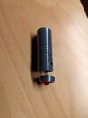
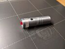
The bodies are from Stapleton and I find them very accurate. Unfortunately, the medical scanner was not included. So I thought about building it myself. I already have the 3D model ready (see pictures, printed in PLA).

What's giving me a headache now is the electronics. There is extremely limited space in the hand scanner. Normally I use a clock chip and a counter chip and transistors to generate the running lights. Unfortunately, there is not enough space for everything in the hand scanner. I thought about using an ATtiny85, but I would need transistors again, as the attiny cannot switch the LEDs directly.

Since I'm not getting anywhere with the problem, I wanted to ask here whether anyone has any good advice for me on how to get the electronics small enough to fit into the scanner or which parts you would recommend. Unfortunately, my grandfather was also a bit clueless. I saw some videos where people assembled a hand scanner but they didn't say anything about the electronics. Everything looked so compact there and I'm starting to get desperate because I can't find a solution on my own.

I look forward to tips and support.
Many thanks in advance! :)
 

Attachments

  • PXL_20231216_220201764.jpg
    PXL_20231216_220201764.jpg
    2.6 MB · Views: 94
  • PXL_20231216_222241718.jpg
    PXL_20231216_222241718.jpg
    2.1 MB · Views: 87
  • PXL_20231216_230109568.jpg
    PXL_20231216_230109568.jpg
    2.2 MB · Views: 88
I would go for a machined Aluminium scanner for real authenticity. GMProps does electronics that uses a board with SMT components to bring the electronics to life.
For a truly top notch replica you could go to Carbon Creative Studios for electronics that have sound as well as lights.
 
I would go for a machined Aluminium scanner for real authenticity. GMProps does electronics that uses a board with SMT components to bring the electronics to life.
For a truly top notch replica you could go to Carbon Creative Studios for electronics that have sound as well as lights.

Yeah, machined aluminium would be nice but I need to start with what I have..
I checked Carbon Createive Studios on facebook. I didn't know them until now. Their work is amazing!!
The boards/circuits are so small and uses just a few parts. I already worked with SMT components in the past but I can't figure out, whitch parts are used here. Any ideas/hints?
 
If you use more board layers you can put the 555 timer on one side and the 4017 on the other. I have driven LEDs directly with those, you don't need a transistor, just current limiting resistors. And since only one output of the 4017 is active at a time you can tie all the LEDs to one current limiting resistor. If you use standard Red, Green, Yellow LEDs they look pretty good at just 10mA, so you can use a really small package resistor (the smallest you're comfortable soldering).
 
Last edited:
Another option is a Seeeduino board. It only has ten outputs, but it is very small and has plugins to program using the Arduino IDE. It is pretty limited, but it's compact and runs on 3V.
 
Sorry but electronics aren't my speciality. I would look to GMProps or CCS for their electronics.
Looking at the red LED you have there, it looks to be a 5mm LED which is a bit too wide, the original prop also used a 4mm green LED for the emitter end and either yellow chaser LEDs for the Voyager style scanner or red chaser LEDs for the FC/DS9 style.

diffuse 4mm LED.JPG
 
If you use more board layers you can put the 555 timer on one side and the 4017 on the other. I have driven LEDs directly with those, you don't need a transistor, just current limiting resistors. And since only one output of the 4017 is active at a time you can tie all the LEDs to one current limiting resistor. If you use standard Red, Green, Yellow LEDs they look pretty good at just 10mA, so you can use a really small package resistor (the smallest you're comfortable soldering).
Hey thanks for your ideas :)
Yeah I also thought about an 555 with a 4017 but both components already take very much space. I tried to put the 555 and a button on one side and the 4017 on the other but if you then also need resistors etc, you quickly run out of space :\

The Seeeduino is a very nice idea but I only have 11,5mm inner diameter. If i make the scanner bigger, it won't fit into the tricorder anymore :(
I'll have a look if there are some smaller boards. We are very close to one of my first ideas to use an ATtiny85 in SMT format.
 
Sorry but electronics aren't my speciality. I would look to GMProps or CCS for their electronics.
Looking at the red LED you have there, it looks to be a 5mm LED which is a bit too wide, the original prop also used a 4mm green LED for the emitter end and either yellow chaser LEDs for the Voyager style scanner or red chaser LEDs for the FC/DS9 style.

View attachment 1887105
Hey thank you very much for that. I was not aware that a flat LED was used for the scanner, in my first idea it was a normal round LED :D

I've also asked CCS what kind of electronics they use but of course they don't want to tell me. I fully understand that as this is their business and nobody likes to tell others about their business secrets :D I've asked if they have any general hints/advice for me and hope they can at least point me in some direction. We'll see :)
 
Hey thanks for your ideas :)
Yeah I also thought about an 555 with a 4017 but both components already take very much space. I tried to put the 555 and a button on one side and the 4017 on the other but if you then also need resistors etc, you quickly run out of space :\

The Seeeduino is a very nice idea but I only have 11,5mm inner diameter. If i make the scanner bigger, it won't fit into the tricorder anymore :(
I'll have a look if there are some smaller boards. We are very close to one of my first ideas to use an ATtiny85 in SMT format.
Hello,
I think SMT could work really well for you. If you use soldering paste, it’ll be super easy to solder. You really only need a 555 timer, a 4017, some LEDs, and one tiny resistor. (Though sometimes I don’t use resistors at all—LEDs can usually handle it if you’re only running your prop for a few seconds or minutes.)
Could you privately share your scanner model? I can import it into Fusion and figure out the best way to fit the circuit.
 
I put together a veeeeeery rough PCB sketch (no optimization at all), and it looks like SMT components should fit into your 3D-printed shell. It’s a single-layer PCB.
The orange rectangle is 12x25mm.
pcb sketch.png


Of course, you’ll still need to figure out the connection to the LEDs. You might find some inspiration (or reverse-engineer a bit) from
this post by GMprops.
 
Seeeduino seems like a great alternative to me—less tinkering and soldering. It also gives you the option to add sound effects to your scanner (using a simple piezo buzzer, for example). But I’m afraid it might be too big and won’t fit.

1734427674558.png


The third option—if you’re into tinkering and that kind of stuff—is using a small programmable chip like the ATTINY85 or something similar. Compared to the Seeeduino, it’s like a rifle versus a tank, but it has everything you need. With two ATTINYs, you could make an LED chaser, a flashing front LED, and even add a buzzer sound effect.

Just keep in mind that you’ll need a programmer to connect the ATTINY to your PC and program it.
https://www.amazon.com/attiny85/s?k=attiny85
 
Last edited:
I would like to give a few of my suggestion for this Medical Scanner although I have no interest in doing it.
As Belgarion stated, the workable space inside the Scanner is 11.5mm, it is do-able.

The Circuitry
What Carbon Creative Studios did showed the tremendous amount of effort in the designing of the electronics. Based on the images, the solution is good.

To generate the animation of the green LEDs, I would use a Microchip PIC, namely a PIC12F629 which has a 25mA output in any of its 5 output ports. If you look at any Videos of the scanner, it seems there are only a pair of LEDs lighting up at the same time, out of eight. So, you only need four outputs, with one output lighting up a pair of LEDs connected in parallel. This also means you only need ONE current limiting resistor for all the 8 LEDs. As the 'timing' of the LED sequence is fixed, you can change to PIC12F675 which is able to read analog signals. This way, you can connect a variable resistor and program the microcontroller to change the timing. The tiny SMD microcontroller replaces the 555 & 4017 ICs, leaving you the space for an audio player (the clue was a small compact speaker in the plastic bags).

As for the audio player, I am not so familiar with the 20-pin chip but for a SMD SOP28 whose maximum width of about 10.3mm, it can still fit into the board. At first I thought it was the APR9600 but that was a 28-pin IC.

The Soldering on the LED is similar when I did the Cylon Raider roving lights in 2011. 4mm LEDs are quite rare and can be very cramped inside the 11.5mm space. I would prefer to use either this type of LED or go into SMD 1206 types (But soldering is quite challenging)

Battery power needs to be a 3.7v Lithium Polymer which again, is still small enough. The prop has no other openings at the bottom (unless you want to screw open the top and slide out the whole circuit board & stuff), so you might have to decide how to access the batteries. Otherwise, all you need then is a connector at the bottom for charging it. I would think a USB-C connector.

The circuit must be designed to 'run' the moment power is applied so, this means, the push button switch does all that.
Definitely needs SMT LEDs for the chaser LEDS that run around the inside of the clear section, anything else would be inaccurate and too big.
PXL_20250206_093305401~2.jpg
PXL_20250206_095339050~2.jpg
 
Last edited:
ESP32-S3 super mini boards are pretty thin. (slightly under .7 inches I think?). (reading above might still be a bit too wide? maybe sanding off one I/O pin side will make it fit)

You also use very small individually addressable leds (WS281/Neopixel) I think 0402 size? So those will def fit in to (anything)
 
Sorry it's a little messy as I just did a quick PCB on the scanner head.

Assuming the workable area is 11.5mm, with a 1mm thick clear perspex tubing, it is possible to use 0805 SMDs and a 5mm LED at the top. You will have to solder the head PCB to the Body PCB via the 10 solder pads, in the shape of a 'T'. They will have to be soldered upright instead of side ways as the two versions of LEDs on the right (LED1 is SideLED, LED2 is 0805) shows. The TOP 5mm (or the rare 4mm) LED will have to split its leads before you can solder it. It is not a 1206 SMD LED. I simply use this footprint as I was busy at work and do not want people to look over my shoulders.

Scanner Head 01.png


But I still think the 2mm axial LEDs (like below) are possible as well, just have to make the 8 pads have 0.8mm holes.
1738898031726.jpeg
 
Back
Top