There has been some recent renewed interest on the forum for The Six Million Dollar Man. This reminded me of an early project I undertook when I had even fewer skills, tools, and funds than I do now. (Although some would argue not all that much as changed.) A friend wanted a “Steve Austin” belt buckle and since she was cute I was determined to make it happen.
There were several differences between what I produced then and what I find others have done over the last five decades. First, it seems the material of choice today is brass. Back then, based on the limited promotional photographs of a non internet world of the day; my choice was copper. As a young electrical engineering student I had access to some scrap; heavy, electrical wire and copper bus bars. This perhaps led me to another major difference in that my buckle was larger than what I see being created in many more recent replicas. I used sections of #8 AWG copper wire for the fourteen “rays” of the buckle. I use the term ray, because I always felt the circle represented the sun, and the projections were rays emanating from it– something an astronaut would find appropriate. This wire has a diameter of 3.25 mm. I used the same wire for the center bar, but I believe I used a steel prong from another belt as copper would not work to hold the belt without deforming. Another factor at the time was America was just making a major push in adopting the metric system. Engineering had been using it for some time, but it was just making its way into common practice. So this was the first time I remember making design decisions in millimeters instead of inches.
One internet example of the buckle today has it sized at 41.5 x 82.8 mm with curved, almost feather-like projections. Others have the projections webbed together to look like a fan. I did not think I was that far off the mark all those years ago so I decided to revisit, and update my recreation. (And yes, the original buckle along with the girl have long since disappeared.)
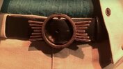
First there are much better images available today. The one I used for this redesign is attached. And although color matching from photographs is always a difficult task – I still believe red copper is still the correct choice over yellow-gold brass. Copper is much more malleable, but that just makes it easier to work with. The rays might be subject to being bent out of alignment but they are all relatively short. Also the rays in the image are obviously straight, rounded-end rods, each separate from one another. To determine the size this time I used three independent references in the same image; the thread stitch count on the pant's fly, and the snap diameter on the jacket and the leather belt width. For the first, sewing machines set their stitch length in mm. The most common are 12 stitches/inch or 2 mm, 10 stitches/inch or 2.5 mm, or ~8 stitches/inch or 3 mm. Long stitches are used to draw attention to the stitch line – like in topstitching. Smaller stitch length is used to “hide” the stitching. Snaps also come in standard Line or Sizes; 20 (12.4 mm), 22 (14.1 mm), and 24 (14.8mm) being very common. The “standard” size for causal belts then and now is 1.5 inches or 38 mm.
In my analysis using the references in combination to cross-validate my calculations; the pant fly is edged-stitched with a 2 mm stitch length, the snap is a Line 22 or 14.1 mm, and the belt is consistent with a 38 mm width. This makes the outer diameter of the buckle's circle 60 mm, the inside diameter 50 mm, and the circle's width 5 mm. This fits well with my dimming memory, as I would have used “rounded off” estimates in my earlier work. The depth of my old buckle was 1/4 inch or 6 mm as that was the thickness of the copper bus I used. For my recreation I will be using 3.5 mm copper rod. I do not have the patience to roll scrap wire in order to get it straight. Also with some slight rounding adjustments I arrive at the length of the projecting rays. Starting with the shortest, center ray and working outward, I have the lengths at; 15, 19, 24, and 29 mm. Again consistent, but at variance, with my memory where I used 15, 20, 25, and 30 mm rays. Although the image says the rays are each 1 mm shorter, I am going to stick with the “easier” numbers. For the buckle you need 2 segments of the shortest length and four of each of the other lengths. In both designs the actual ray length is/may be slight longer based on assembly technique. My originals were all 5 mm longer, again giving easy to measure and cut 20, 25, 30, and 35 mm segments. I then drilled holes completely through the circular ring and soldered the rays in place. If I were using brass today I would use the smaller actual lengths and just silver solder the brass rods to the outside of the brass ring. Either method probably requires a jig to either drill the holes or hold the rods in place for soldering.
As an aside, since I did not have a 3.25 mm drill bit in the 1970s, I chucked each rod segment into my (corded) hand drill and made a jig to sand the last 5 mm of the rod down to 1/8” for which I DID have a drill bit. I used the drill and sandpaper to round the ends.
I also made a jig to drill the holes into the ring. The center ray is at 90 degrees to the ring so that gave me a strong point of attachment and alignment for the jig. I drilled the ring for this hole on each side. The angle for the other three holes differed from 90 degrees, but the three above and the three below the center are symmetrical so once the first three where drilled, I turned the jig on the center ray pivot and drilled the second set of three. And then did the same for the other side of the buckle. I do not remember the distances and angles I used then, but I have calculated ones from the more accurate images. The angles are 88, 85.5, and 83.75 (I probably used something like 88, 86, and 84 originally.)
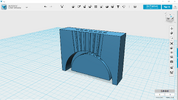
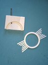
To help me and others who might want to make this buckle I printed a 3D jig. With this one you do not even need to pivot the jig for each side. The jig assumes the 60 mm OD ring with a 5 mm ring thickness and a 6 mm depth. The holes are 3.6 mm to provide a little tolerance for the 3.5 mm drill bit. After my own test I added some grooves on the top surface to provide some guidelines to better sight the drill. For others this might just be used to center punch locations for the holes you wish to use. The center hole of the jig can also be used to position the center bar. An illustration and image of my printed jig are also attached.
")