gmontag451
New Member
This is my first post, I hope I'm in the right place!
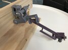
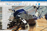
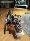
I'm making a replica of Rover, the animatronic dog from Disney's Carousel of Progress! My wife and I met working in Tomorrowland and we've wanted to build one for years. Using photos and a maintenance manual I found online, I've been building the pneumatic mechanics in Fusion 360, which I plan to adapt to work with servo motors. My wife will sculpt the shell and design the fur once the insides are resin-printed and assembled.
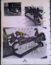
I think I have a pretty good idea of what each joint does, but the photos are very dark and it's difficult to figure out what's going on. I could forge ahead and make it work, but I'd like to stay as close as possible to the original before adding servos. I'm hoping someone might be able to provide some guidance!
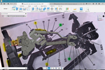
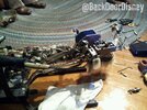
This is what I have so far: The two main actuators lift the neck up and down and sway the neck left to right. I believe that actuator 7 (highlighted in yellow in the photos) makes the head turn left to right, 6 seems to make the head nod, and 32 probably makes the head cock right and left. I've also just finished building the eye mechanism in 3D.
The areas I can't sort out are:
- Around point 24 are two or three joints which I think might be solid and immobile.
- I can't figure out where actuator 6 or 7 connect... In one photo 6 seems to be very short and doesn't reach the head, but in another it seems to be very long. Actuator 7 seems to have a long curved bar to extend its reach, but I can't figure out where it connects because the angle seems wrong. (My guesses are the backside of point 12, backside of 23, or left side of head)
I'll keep posting my "Progress" and if anyone has any thoughts about how this guy works, I'd really appreciate any ideas! (The angles and connections below are inaccurate because I'm just trying out a quick way to make it work and fix it later.)
I'm making a replica of Rover, the animatronic dog from Disney's Carousel of Progress! My wife and I met working in Tomorrowland and we've wanted to build one for years. Using photos and a maintenance manual I found online, I've been building the pneumatic mechanics in Fusion 360, which I plan to adapt to work with servo motors. My wife will sculpt the shell and design the fur once the insides are resin-printed and assembled.
I think I have a pretty good idea of what each joint does, but the photos are very dark and it's difficult to figure out what's going on. I could forge ahead and make it work, but I'd like to stay as close as possible to the original before adding servos. I'm hoping someone might be able to provide some guidance!
This is what I have so far: The two main actuators lift the neck up and down and sway the neck left to right. I believe that actuator 7 (highlighted in yellow in the photos) makes the head turn left to right, 6 seems to make the head nod, and 32 probably makes the head cock right and left. I've also just finished building the eye mechanism in 3D.
The areas I can't sort out are:
- Around point 24 are two or three joints which I think might be solid and immobile.
- I can't figure out where actuator 6 or 7 connect... In one photo 6 seems to be very short and doesn't reach the head, but in another it seems to be very long. Actuator 7 seems to have a long curved bar to extend its reach, but I can't figure out where it connects because the angle seems wrong. (My guesses are the backside of point 12, backside of 23, or left side of head)
I'll keep posting my "Progress" and if anyone has any thoughts about how this guy works, I'd really appreciate any ideas! (The angles and connections below are inaccurate because I'm just trying out a quick way to make it work and fix it later.)
Attachments
Last edited:
")