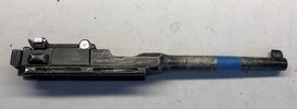
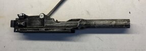
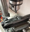
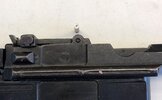
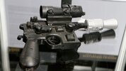
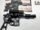
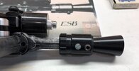
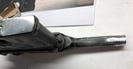
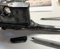
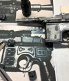
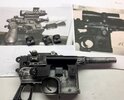
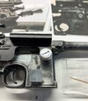
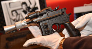
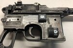
ROTJ Han Solo DL44 (Bunker Version) Build

Corellianexports

Master Member
RPF PREMIUM MEMBER
Han Solo ROTJ.jpg


I don't think I've ever posted a build thread for a ROTJ blaster from start to finish so here we go. :)

So I'm starting with an older version of the Denix Mauser for this one. Apparently, some one bought this, shelved it and never got around to converting it. In my workshop, these Mausers don't sit idle for very long. :p

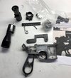
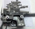
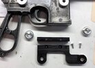
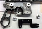
First step is to remove the ring, take it apart and clean up every thing with a clean rag. I like to store the little bolts in a small box so they don't get lost:

IMG_1752.JPG

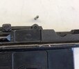
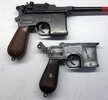
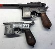
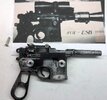
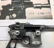
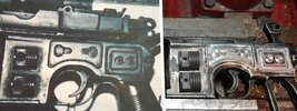
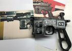
I usually give the main parts a bath in soapy water before doing any thing more, but in this case I wanted to start with the Mauser detailing so I could detail a couple of other Mausers (ESB conversions) at the same time, so I started by machining the left side details and then the indented areas which need to be widened slightly to match the measurements of the MGC (Pictured above the Denix):

IMG_1754.JPG

Onto the right side. I machined the center area which needed to be widened and lengthened:

IMG_1755.JPG

The two, smaller indentations will need to be lengthened, but it's time to take a break and let these sit in some dish washing detergent over night.
 
After leaving the parts overnight in soapy water, rinsing and allowing them to dry, the next step is to sand them with 220 grit sand paper:

1EBFAFC2-B28E-47B9-AA82-62752F425AAE.jpeg

In my early days of doing this, probably because of my machining experience I didn’t wear gloves but if you want to avoid blackening your hands, vinyl or rubber gloves are highly recommended.
I sand down all the outer surfaces including the trigger and hammer.

Once that’s done I toss the gloves, put on new gloves and use a clean rag with some denatured alcohol to clean all the parts, inside and out. I use cotton swabs to clean the small indentations,corners, holes and the magazine area.
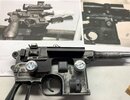
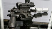
Once dry, I fill in the indentations with JBWeld. Before applying JBWeld to the underside of the sight, I use some 220 grit sand paper near the center of the part and the Mauser to rough up the surfaces a bit.
Just a small amount of the glue is needed, otherwise it will spill out between the parts:

37E3AC7D-CA6C-4524-8266-C7B8A7821E4B.jpeg
 
Last edited:
The next step is to take some 220 and 400 grit to smooth down the areas with JBWeld, making sure these areas are as flat as possible.
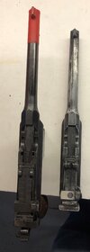
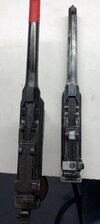
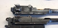
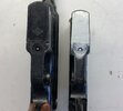
Now it's time to machine the upper. In this comparison shot, we can see a couple of major differences, which include the filled in area near the rear sight and the missing indentations near the magazine opening:

IMG_1833.JPG

I machine these areas with a mill. At the same time, I machine the raised areas near the sight hinge on either side of the upper:

IMG_1835.JPG

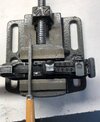
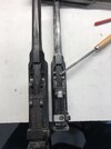
I use a square file to make the machined areas rectangular:
IMG_1837.JPG

IMG_1838.JPG

Up next, finishing the machine work on the lower and adding some fine details to the upper.
 
Last edited:
This is an awesome start! I’ve dreamed of getting a small mill for years, basically just to do this stuff to Denix Mausers haha!
 
I paid around $500 for the one I have back in 2001. I think they are around $750 today. I have gotten a lot of use out of it. Every thing from Mausers to SS models.
 
Continuing with the upper, I used an artists saw (by X-acto) to deepen the vertical lines on the sight button and then saw horizontal lines which are similar in spacing. Because the area was uneven, it was sanded down and then buffed. I also used a small file to smooth down the area around the button.

I used some painters tape to mark the area on the barrel that needs to be cut off (1 7/8" from the end of the barrel) to fit the flash hider:

IMG_1844.JPG

I just used a hack saw and a mill to clean off the end. A belt sander will work just as well. I used mine to round off the edges:


IMG_1846.JPG

One final detail is left and that's the sight lever pins. There are a couple of ways to go about upgrading these guys. One way is to replace them with rolled pins, like the originals. The only problem is that the hole that is left is larger than the one in the MGC upper, so if you decide to go this route, the hole will need to be filled with JB Weld and then re-drilled to fit the smaller roll pins.
Another way to do it is to drill a very small hole at the center of the pin and then machine or file/sand the edges. I start by drilling a tiny hole with a #64 jewelers bit:

IMG_1847.JPG

Once that's complete, the edge of the pins will need to be machined down at an angle (I selected 20 degrees) to simulate the look of a rolled pin.
I used a narrow punch with a hammer to remove the pin. Here's a before shot with the MGC pin:

IMG_1848.JPG

After machining:
IMG_1849.JPG

After putting back the pin:
IMG_1850.JPG

The upper is finished. Next up is the lower.
 
Last edited:
I took some measurements of the rectangular indentations on the right side of the Mausers and although they're shorter on the Denix, if they are lengthened it will adversely effect the overall look of the Mauser, so that's going to do it for the indentation machining. On to the bottom of the magazine.
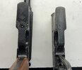
Here's a comparison shot with the MGC. I used a template to mark the area that needs to be machined to create the look of a functioning magazine:

IMG_1851.JPG

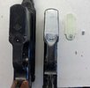
I used a 5/8" end mill to remove just enough material to create a slight indentation. Then I used a small counter sink with the same diameter as the outer diameter of the hole at the bottom of the MGC magazine (11/64"?) to recreate the hole. A (3/16"?) drill bit was used to create a hole for the rounded pin. I used a cut down rivet. Here it is with the template, Denix and MGC:

IMG_1852.JPG

And here it is installed. I used a couple of drops of super glue to keep the pin in place:

IMG_1853.JPG

Up next, installing the original, plastic grips with machined hardware and starting the pre-assembly.
 
One of the details about the Denix I have a real hard time with are the bulky, slotted bolts on either side of the grips. Even worse is the fact that all of the Han Solo blasters (with the exception of the ROTJ MoM) don't even have a slotted bolt head on the right side, which is how the blaster is displayed.
So having a slotted bolt without hardware, on the right side of the blaster just doesn't work. It's only saving grace is that it's black.

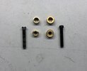
For the hardware, I used a set I purchased from a website. It's basically a reproduction and it's a little oversized, but I was able to machine the parts down to the same size as the hardware found on the MGC. I was even able to add a little knurling to them. Here's a comparison shot (original set on the right):

IMG_1872.JPG

Also, I checked the MGC hardware and the materials used is identical: Steel for the bolt and brass for the hardaware.

To get this hardware to fit the Denix, I used a 11/64" drill bit for the hole in the grip area (straight through) and 5/16" bit for the grips (almost all the way through):

IMG_1870.JPG
IMG_1871.JPG

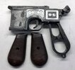
Here's the fitted assembly with the MGC for comparison:
IMG_1868.JPG

Left side:
IMG_1869.JPG

Up next, blackening the grip hardware, machining some missing parts and drilling lots of holes (Welcome to the Star Wars Universe!) into the Denix. ;)
 
Last edited:
Thanks.

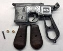
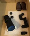
So the next step is to catalog the parts I already have and figure out what needs to be machined:

IMG_1899.JPG

I'm missing the knobs. Back in the day, I use to machine them out of brass, but looking at some recently released reference photos, the knobs appear to be made of aluminum or a light colored Derlin. I'm going to opt for aluminum since I have plenty of it in stock.

Once that's done, I'll get the railing machined and attached to the mount.
 
I spent a good amount of time looking through reference photos and scaling up the knobs in comparison with a real MGC Mauser.

The knobs are different from the MoM version of the blaster. Another thing that is interesting to note is that the bolts used on the Bunker version were also different from the MoM version. It looks like most all of the ROTJ blaster parts I have in stock are actually for the MoM version, which makes this project more of a challenge. :unsure:

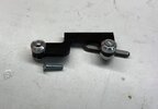
Once I found the correct version of the bolts at a local hardware store, I was able to machine some accurate knobs along with some spacers to go with them:

IMG_1957.JPG

While looking at the reference photos, I discovered that the mount is also different from the MoM version, so I will need to design a new template along with a new mount...
...and if I remember correctly, this was just as much a headache the last time I built one as it probably is now. :p

Up next, tackling the "bunker" mount.
 
Last edited:
Nice work! Do you have any comparison shots or details? Im wondering if they were all hand made and thus different or one used more found parts that were copied
 
Nice work! Do you have any comparison shots or details? Im wondering if they were all hand made and thus different or one used more found parts that were copied
I can post some photos once I get the mount going. I'm looking at several different reference photos at this point.

From what I can tell, it looks like once the MoM version was built, the prop guy realized that he didn't have any more of the same bolts available, so he used the closest ones he had, which may have been metric. I think it's safe to say that all the parts were made by hand because not only were the knobs different from blaster to blaster, but they were also different on the same blaster, which is true of the Bunk version. In fact, it does look like there were actually two different "Bunker" blasters. Here's the one with the two, different knobs:

blaster2.jpg

this one appears to have the same size knobs:
ROTJ Bunker Right.jpg
 
Using the knobs with the Mauser and the reference photos, I was able to pin point where the mount should sit and just how long it should be. The back half of the mount was too long, so I shortened it by about 1/4":

IMG_1977.JPG

Here's the set up with the other reference. I still think the knob on the right side should be closer toward the center of the Mauser, but it's only off about 1/16". The problem with trying to make this adjustment is that the mount would have to be cut in half and then put back together:

IMG_1978.JPG

Now it's on to the railing. I have just enough to cover the top of the mount, so I use a hack saw and then a mill to clean off the ends.
The mount didn't come with bolts, but I noticed that the holes in the mount were counter sunk, so I check my box of blaster bolts and find the smallest set I have. Ironically, the ones that fit are from my GK mounts and my Han/Luke droid caller slides:

IMG_1981.JPG

I mark the railing, using the mount as a guide with a punch. The holes are threaded with a 4-40 tap:


IMG_1980.JPG

And she's done. I do a test assembly to make sure every thing lines up and fits properly:

IMG_1979.JPG
 
Last edited:
I test fit the flash hider and realize that's too far forward in comparison to the reference photos. This is probably because this is the first time I've worked with a derlin flash hider and the inside may have different dimensions:

IMG_1982.JPG

So the next step will be to adjust the barrel. After that, the piston halves and bump will need to be installed before painting can begin.
 
After removing a little material off the end of the barrel, I test fit it. I checked another reference photo along with my own, Bunker blaster and it looks like the distance from the end of the scope to the edge of the flash hider is 3/4":


IMG_1990.JPG

While I'm working the flash hider, I realize that I need to add a slotted bolt. Again, I end up using an old GK blaster bolt that fits the correct dimensions. The existing hole is counter sunk:

IMG_1991.JPG

To make sure that the flash hider sits correctly, I use my belt sander to create a flat area on the bottom of the barrel:


IMG_1992.JPG

I make sure that the pins and screw are in place before test fitting everything. I also want to make sure that the hammer works correctly.
Every thing looks good, accept the bulky screw. I remove it and shorten it using my handy, dandy belt sander.
I put the screw back and mark any areas that need more sanding with a sharpie. I continue the process until it looks almost invisible from the side:

IMG_1993.JPG

Up next are the piston half and bump installations.
 
I noticed in the newer reference photo that the slotted bolt is deeper in the flash hider than I had realized, so I counter sink the hole a little more.
Before moving forward with the piston half installation, I need to expand the piston half bolt areas using a 1/4" end mill. Here's a before pic:
IMG_2002.JPG

The expanded area is toward the the "grill" area of the piston half. I think the reasoning behind it was to get enough room for the 1/4" diameter bolts that were used. With the pistons machined, I use the reference photos to get the bump placed in the correct spot. Although the bump is placed different on both Bunker blasters, after looking at the MoM blaster, I noticed a pattern: All the bumps are centered within the mount area, so this is how I place the bump:


IMG_2003.JPG

I'm not working with a rubber bump, so I use my belt sander to create a step at the bottom of the bolt so it sits flat on the Mauser:

IMG_2004.JPG

I use some contact cement to attach the bump and super glue to attach the piston half. I use 220 grit to sand the areas on Mauser where the parts will sit, and then the parts before placing them:

IMG_2006.JPG

I noticed in the newer reference photo that the Phillips head bolt appears to be completely flat. It's very difficult to tell if the bolts are flat on the left side of the blaster, but since all of the bolts used on the blaster were counter-sunk into place, it only seems to make sense that this is how it was done on the left side. Here's the newer reference for the right side. Notice that the bolt for the piston half is completely covered in dust:

blaster2.jpg

And the left side:
juliens-star-wars-blaster-n.jpg

Both parts are drilled, tapped and counter sunk. Here's the Mauser with the bolts installed:
IMG_2010.JPG
 
Last edited:
While looking at the new, left side reference pic, I noticed that the machining at the center of the Mauser is different, so I decide to stick with my original reference photo for the placement of the piston halves and the bolts. Here's a side by side comparison with the piston halves in place, ready to be glued:

IMG_2007.JPG

And here's the left side with the new, flat head bolts installed. Ironically, these are some of the same bolts I used to built my full scale R2 with:

IMG_2008.JPG

Because the dry, warmer weather is quickly becoming a thing of the past, I decide to put in the over time and get every thing cleaned up and ready for painting ASAP. The Mauser is thoroughly cleaned inside and out with denatured alcohol, then reassembled for the final time. Because I'm using a real scope, the lens area is taped off with painters tape:

IMG_2009.JPG

IMG_2035.JPG
 
Last edited:
Back
Top