Working on lower docking arms...

Man, that's some tricky geometry!
Man, that's some tricky geometry!
JCoffman,Here's a side view if it helps. Not much to go on.
View attachment 1809781
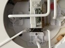
agreedCould you post a picture of that muffin fan please?
Thanks!These are the best I have of that area.
View attachment 1821516
View attachment 1821518
View attachment 1821530
View attachment 1821532
Thirded, ; )
I think so. It looks like they needed something just to fill the gap. Probably pieces of styrene.Thanks!
It "almost" looks like it might be two separate pieces, no?
All of the above; after the main design was done, then it's "simply" a game of finding the "right" greeblies to put on that form and using a sense of "real world look" as to which part fits in with other parts (creating a story). Sure, lots of cutting, fitting, etc...to achieve that look, but that's the fun of building Sci-Fi models from scratchIt's so interesting that the original builders put together the main falcon "form" then just tested greeblies and either cut to fit, or said "too big, nope, dang this one is too small, aaah!! This fits just right - where's that little bottle of Eastman glue??" And everyone else is slaving and fretting over sub-millimeter dimensions trying to recreate what was just literally bashed together- so brilliant!!!

Shamon to the Rescue with the Right Shaman!This is the right shaman. This kit fits the width of the track.
 www.therpf.com