nstevic01
Well-Known Member
I started this thread over on GBfans and figured I would post it up here as well:
This has been a long time in the making. Last year when we met the Suncoast and Orlando guys I was inspired to begin my pack build. I spent the next 4 months tracking down each individual component and made a list. Once I got my Bonus and Tax return, I started placing orders.
After 9 Months of research, ordering, and waiting, I am now at a point where I can get started. The last main component I am missing is the thrower, I ordered one from CPU64 about 5 months ago so it should be close to being finished.
I would also like to say thank you to ALL of the seller's listed below, you have been awesome to deal with and I appreciate the time spent answering all of my questions. You will be the ones I point to when someone wants to build a pack. A big thank you goes to AJ for providing a easy place to get some of the specialty parts, but my bank account hates you.
I am debating on placing up my excel tracking sheet which has listed all of the parts, sellers, prices, and shipping costs to give someone new an idea of what it costs to build one from the ground up. Had I have known how much I was truly going to spend sourcing everything, I might have just bought a "starter" pack for half the cost and gone from there.
Let's just say I am now north of $2000, not including CPU64's thrower, paint, primer, filler, etc...
Parts list to date:
Real Parts:
- LC-1 Alice Pack frame and straps with correct NSN's
- Clippard R331
- Clippard R701
- Clippard brass elbows and barbs
- Dale PH-25 resistor
- Dale RH50 resistor
- Crank knob
- Sage resistor
- Arcolectric clear and red indicators
- Orange and White Hatlights
Replica Parts
- Legris straits
- Legris banjos
- SMC elbows
Vincenzo330's:
- Motherboard
- bigi330 shell
- aluminum HGA
- aluminum booster tube with plug
- aluminum n-filter
- aluminum vac line
- aluminum beam line and filler tube
- aluminum cable clamps
- aluminum injector tubes
- aluminum ppd
CPU64's:
- aluminum ion arm
- aluminum thrower set (on order)
Anhcon's:
- aluminum ion arm assembly
- aluminum v-hook
- acrylic tube w/trigger tip
- aluminum gun track
- splitless loom locking ring
eBay:
- aluminum shock mount (to hold me over until AJ's real bellows are done)
Nickatron's:
- booster frame
- bumper
Multimedia Mahem's:
- thrower grips
- full tubing set
GBFans':
- aluminum side knob set
- bellow replica (on waiting list)
- Aluminum Heatsink
GhostGuy's:
- Mighty Microcontroller for lights and sounds
Crix's:
- power cell and cyclotron lens set
JoeLuna33's:
- aluminum label set
gEkX's:
- hardware set
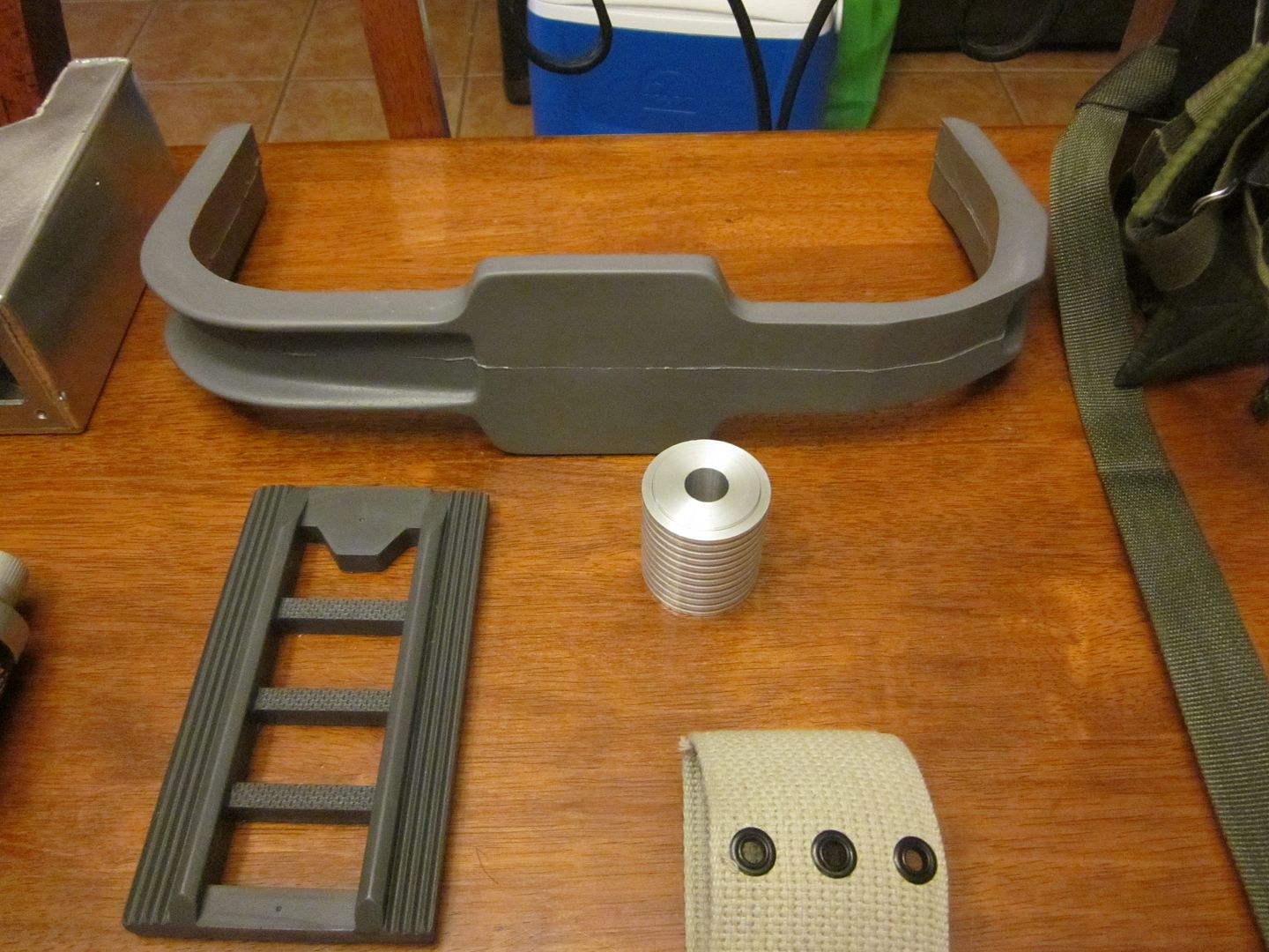
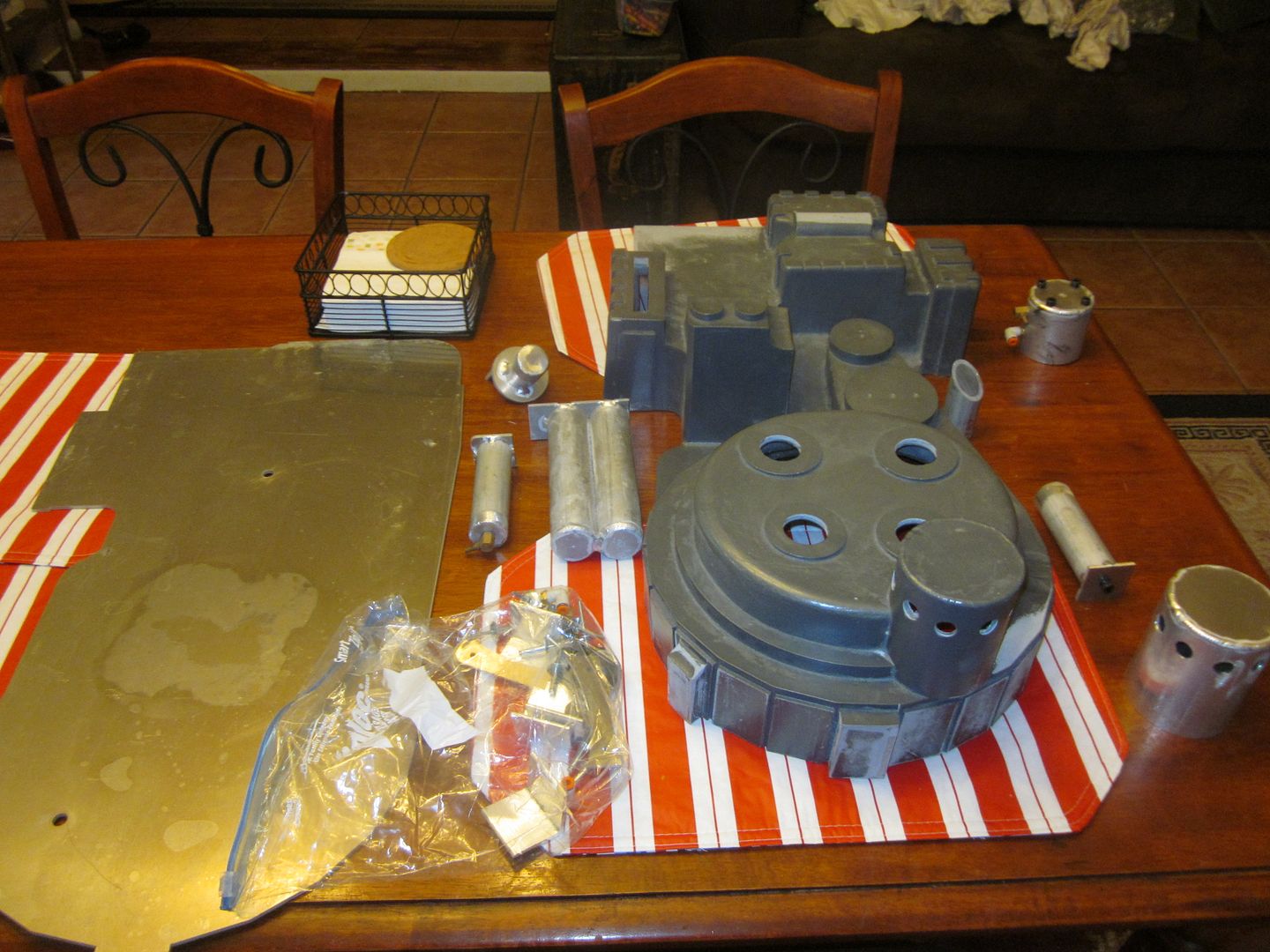
And of course the pictures, there are some missing, but this is what I have on my HD at this time. I will transfer the rest later:


I started with mounting the brackets to the mother board. I traced the shell out on what was the best centering I could do. I will have to trim a little of the board towards the bottom where it does not line up just right. Once I traced the shell, I used a micrometer to measure the thickness of the pack walls where the brackets were placed and used those numbers to place the bracket.


Once I got the brackets on, I worked on tapping them to be mounted. Once I had the shell lined up on the board, I used clamps to keep the shell as flush to the board as possible while tapping.

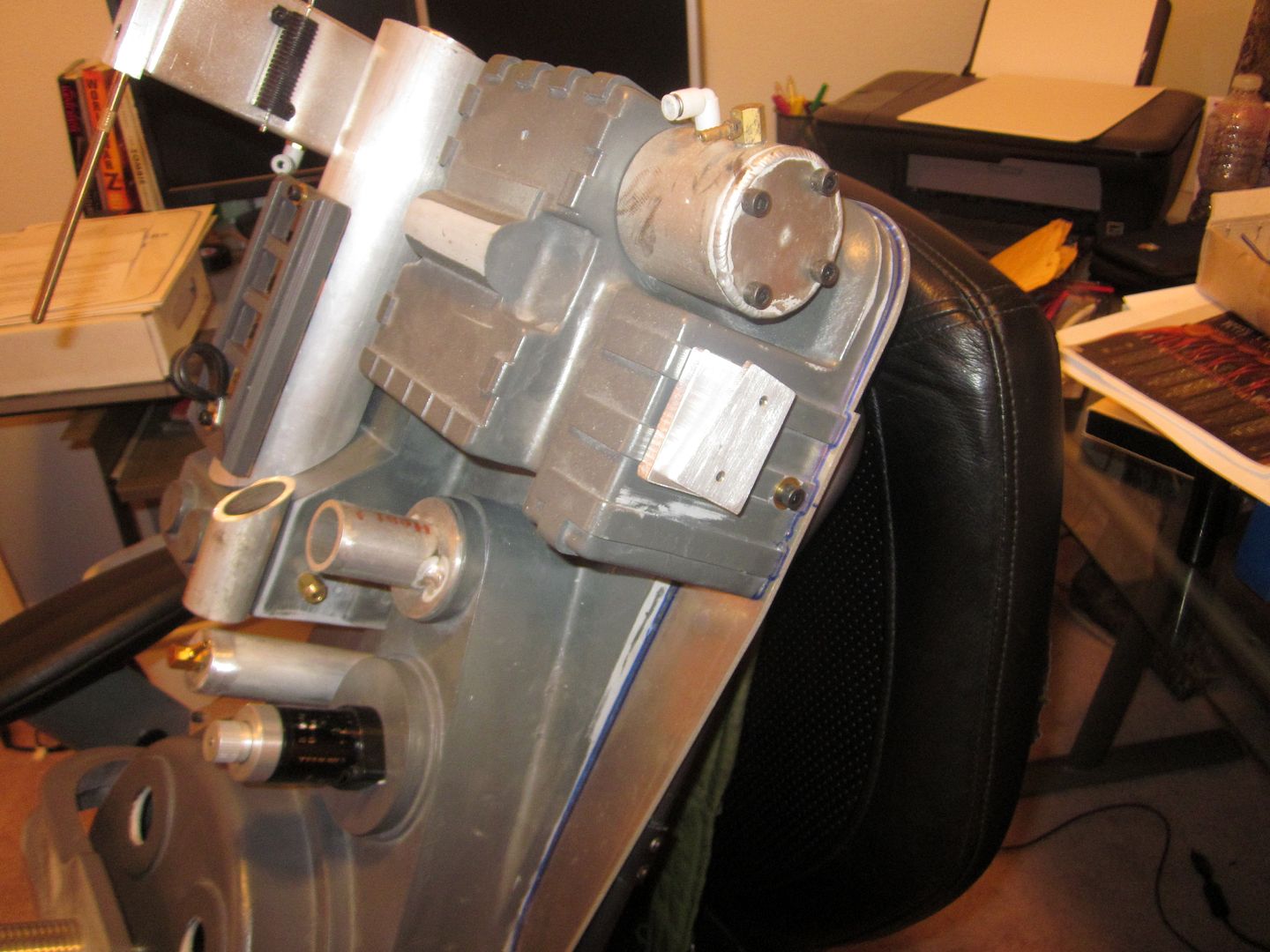
Test fitting the shell to the board

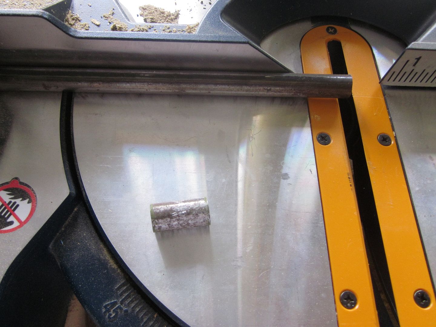
I went with 3/8" bolts to mount the pack to the ALICE frame. Since I could not find spacers for the bolts, I picked up some steel tubing to make my own. I started with 1" spacers, but found out that GB1 packs used 1/2" spacers. So I had to cut new ones, pictures below are of the 1" ones.

Also picked up the rubber spacer that the metal one will sit inside. I will need to paint it black, but it was as close as I could find.

ALICE frame mounted to motherboard, used wing nuts to secure on the backside.


Mounted the bumper, booster frame, and PPD. I never would have thought it would take so long to get everything mounted up.


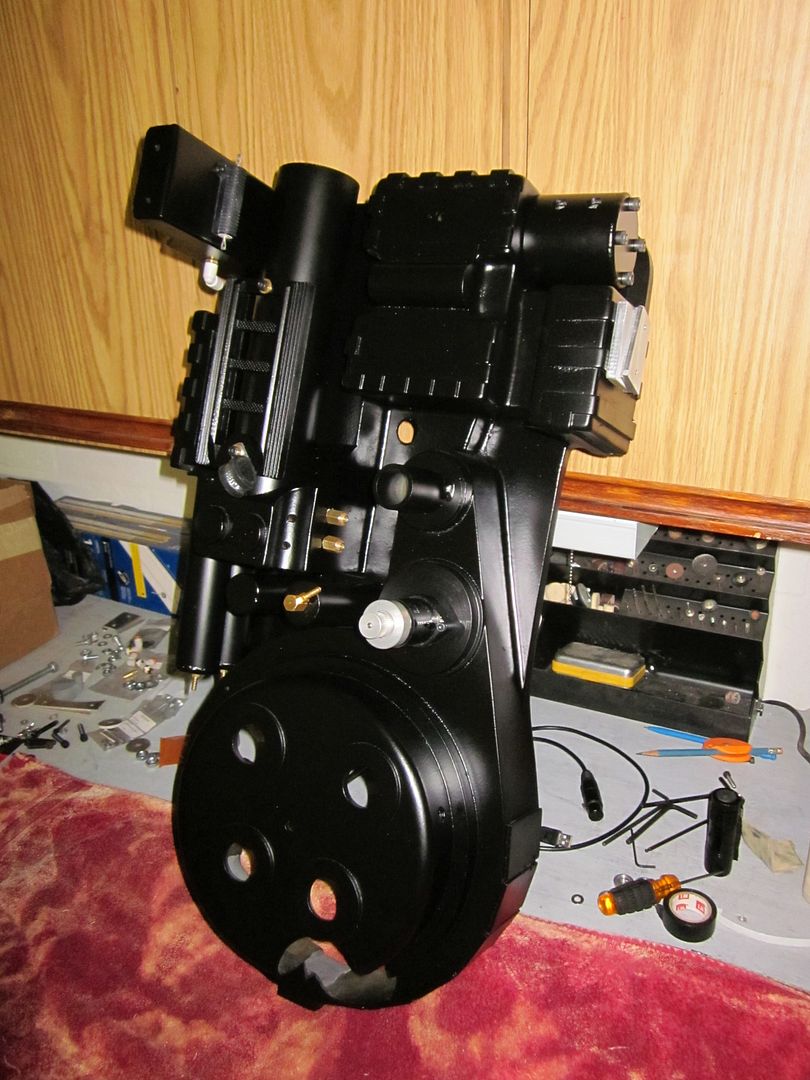
She is fully primed and currently drying. I do not plan on weathering the pack just yet, I'd like to enjoy the fresh off the workbench for a bit.


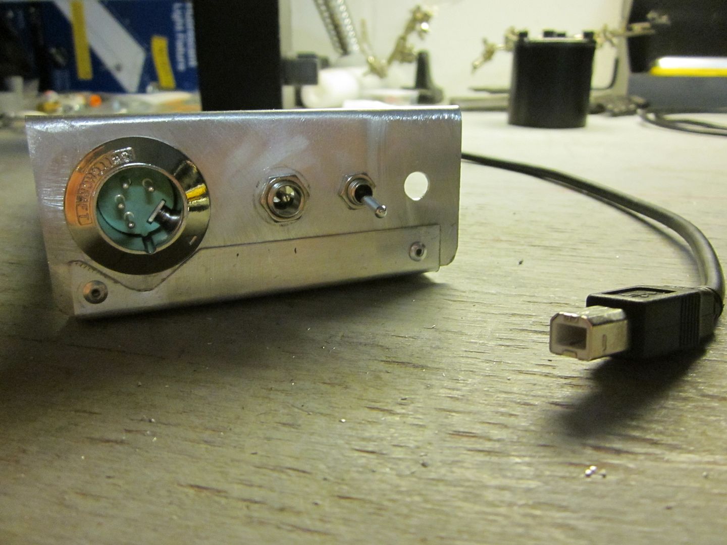
While waiting for the paint to dry, I am working on a little something for the XLR/Switch panel. Since I am getting the Mighty Microcontroller for the lights ans sounds, I figured I would wire up the XLR connector for USB connection and use the DC barrel plug for charging. I ordered up a Switchcraft 4 pin socket and a female 4 pin connector.


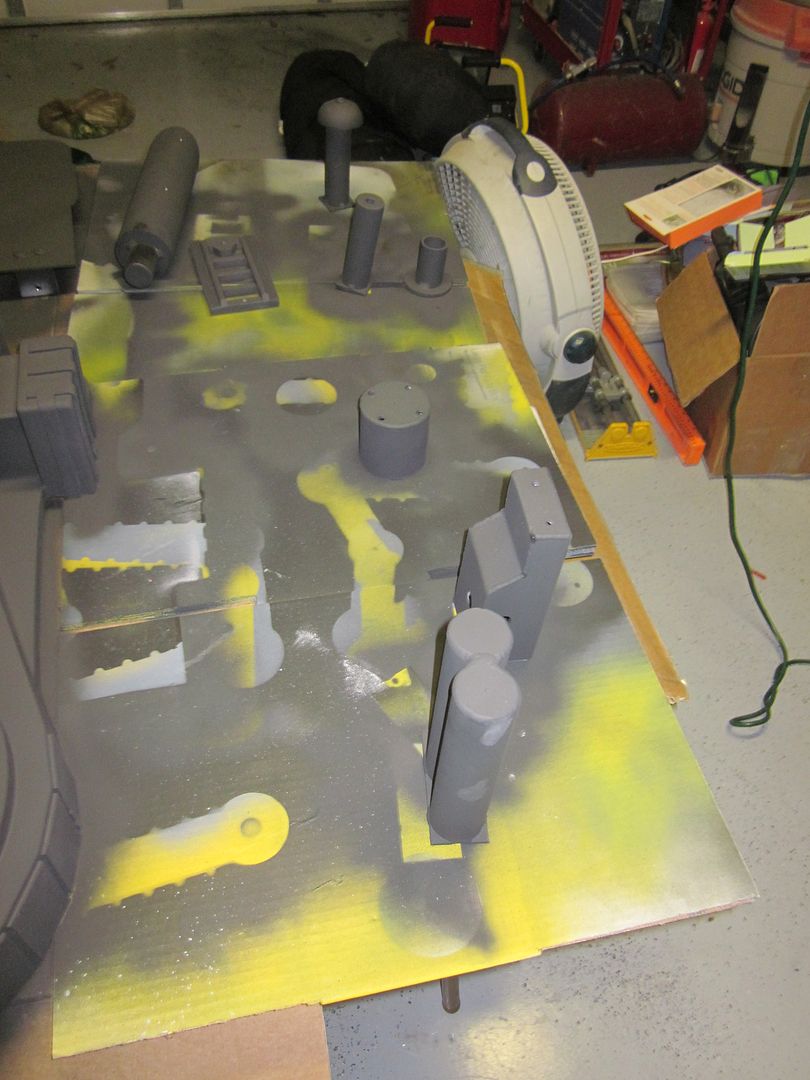
Finally got the painting done, on to some assembly...


I tore apart an oil filter and took the bottom plate out, then welded it inside the N-filter. I will be using this to attach and detach the N-filter. Reasoning behind this, is a "reveal" N-fitler. I'm not 100% on the internal design, but I wanted to make something that could possible represent what was meant to be there. So I will be studying Nitrogen and Liquid Nitrogen filter designs and come up with something that is visually appealing.

Started closing off the N-filter mounting area and will be working on the pole that the filter will mount on.

Just got back from Home Depot....should have the mock up in a couple of days.
As far as the filtration goes, this was one of the only filters I was able to find. Apparently it's not very common to filter LN.

For those interested in specs:
While researching the properties of LN, I came across this:
So if I am understanding this correctly, in the event of pack components overheating and causing the LN to expand, there would need to be some sort of venting system in place for safety. Probably why the VG Pack has the ability to do so.
This of course gives me the excuse to rig up an emergency venting system, which will be vented through the N-Filter holes. I already have an idea of how I will do it. A guy building an R2 unit came up with the idea, and it apparently works well. The mighty microcontroller should be easy enough to program the solenoid to work with the fore-button on the barrel. Link to his blog if you want to check it out: Victor's R2D2 Building Diary: August 2007
I still need to work up the filter element and sprayer but here is the beginnings of the mount. It will be riveted to the motherboard and will require that the filter be unscrewed to disassemble the pack.

So here is the completed mock-up with the filter off:

Filter on:

I am thinking about painting the whole rig chrome, to kinda represent the polished look of the actual LN Filter I posted earlier. Let me know what you guys think.
Mounted to the motherboard:


And of course the mock-up for the venting system. I used the smallest copper tubing I could find, and will be drilling tiny holes in the "ring" which will line up with the vents on the N-Filter. I will be digging out some old R/C car servos I have in the shed and will use those for controlling the venting.

Venting test with only tubing and manual control:
Proton Pack Venting Test - YouTube
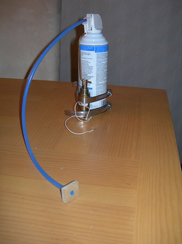
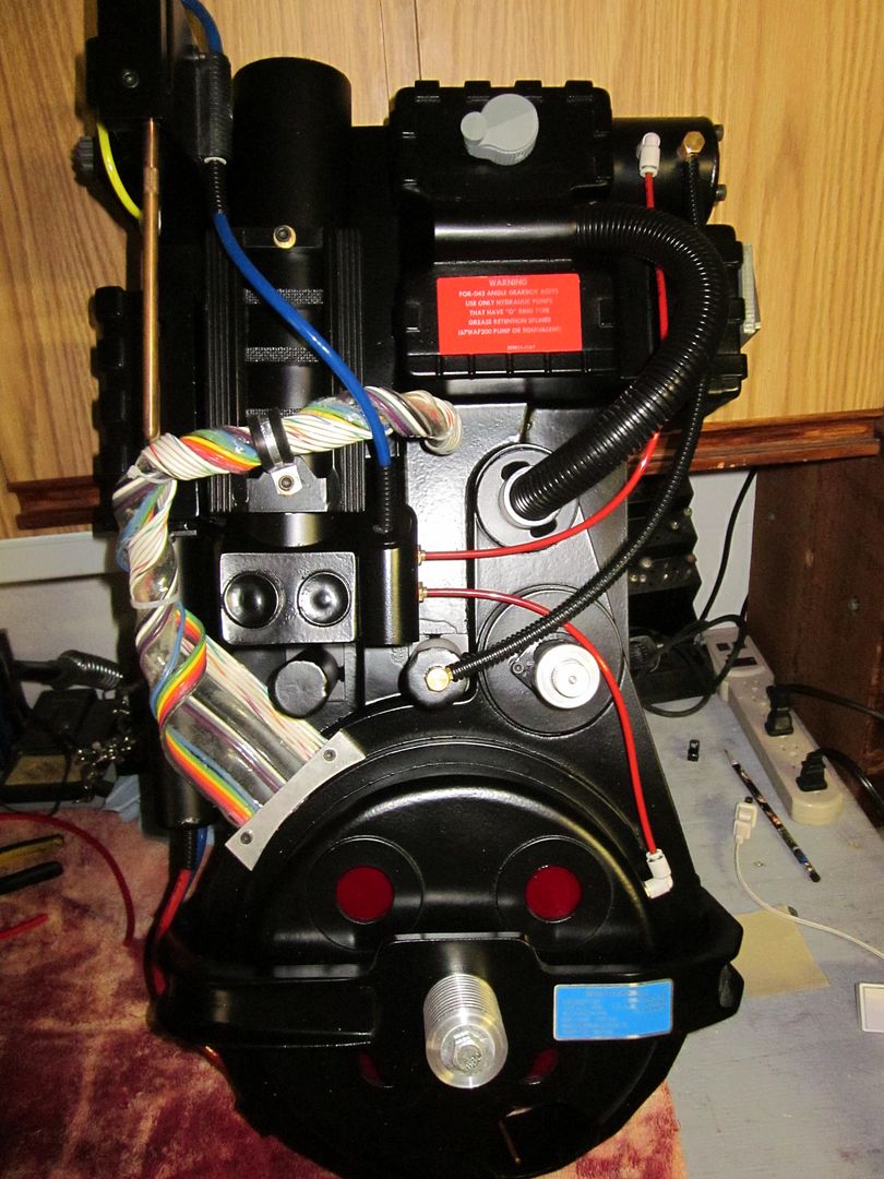
I managed to get the compressed air can mounted and the trigger mechanism rigged. There is NOT alot of room in the pack for the can, there is literally only one place it can be mounted without it being in the way of everything.
I had to remove the bolts that hold the booster tube in, since I could not get the clearance I needed. I fabricated some brackets out of the bolts I removed and pod gauge mounts.

Installed, they now hold the booster tube in and hold the air can

Actuator mounted with the can

and of course a video of it working
Proton Pack Venting Actuator - YouTube
For those of you wondering, this is the actuator I used, not bad for $1.74 shipped on eBay

And this is where I am today, Assembled Proton Pack venting test. This is with the actuator wired up to a 12v battery and a momentary push button
Assembled Proton Pack Venting Test - YouTube
More to come!
This has been a long time in the making. Last year when we met the Suncoast and Orlando guys I was inspired to begin my pack build. I spent the next 4 months tracking down each individual component and made a list. Once I got my Bonus and Tax return, I started placing orders.
After 9 Months of research, ordering, and waiting, I am now at a point where I can get started. The last main component I am missing is the thrower, I ordered one from CPU64 about 5 months ago so it should be close to being finished.
I would also like to say thank you to ALL of the seller's listed below, you have been awesome to deal with and I appreciate the time spent answering all of my questions. You will be the ones I point to when someone wants to build a pack. A big thank you goes to AJ for providing a easy place to get some of the specialty parts, but my bank account hates you.
I am debating on placing up my excel tracking sheet which has listed all of the parts, sellers, prices, and shipping costs to give someone new an idea of what it costs to build one from the ground up. Had I have known how much I was truly going to spend sourcing everything, I might have just bought a "starter" pack for half the cost and gone from there.
Let's just say I am now north of $2000, not including CPU64's thrower, paint, primer, filler, etc...
Parts list to date:
Real Parts:
- LC-1 Alice Pack frame and straps with correct NSN's
- Clippard R331
- Clippard R701
- Clippard brass elbows and barbs
- Dale PH-25 resistor
- Dale RH50 resistor
- Crank knob
- Sage resistor
- Arcolectric clear and red indicators
- Orange and White Hatlights
Replica Parts
- Legris straits
- Legris banjos
- SMC elbows
Vincenzo330's:
- Motherboard
- bigi330 shell
- aluminum HGA
- aluminum booster tube with plug
- aluminum n-filter
- aluminum vac line
- aluminum beam line and filler tube
- aluminum cable clamps
- aluminum injector tubes
- aluminum ppd
CPU64's:
- aluminum ion arm
- aluminum thrower set (on order)
Anhcon's:
- aluminum ion arm assembly
- aluminum v-hook
- acrylic tube w/trigger tip
- aluminum gun track
- splitless loom locking ring
eBay:
- aluminum shock mount (to hold me over until AJ's real bellows are done)
Nickatron's:
- booster frame
- bumper
Multimedia Mahem's:
- thrower grips
- full tubing set
GBFans':
- aluminum side knob set
- bellow replica (on waiting list)
- Aluminum Heatsink
GhostGuy's:
- Mighty Microcontroller for lights and sounds
Crix's:
- power cell and cyclotron lens set
JoeLuna33's:
- aluminum label set
gEkX's:
- hardware set
And of course the pictures, there are some missing, but this is what I have on my HD at this time. I will transfer the rest later:
I started with mounting the brackets to the mother board. I traced the shell out on what was the best centering I could do. I will have to trim a little of the board towards the bottom where it does not line up just right. Once I traced the shell, I used a micrometer to measure the thickness of the pack walls where the brackets were placed and used those numbers to place the bracket.
Once I got the brackets on, I worked on tapping them to be mounted. Once I had the shell lined up on the board, I used clamps to keep the shell as flush to the board as possible while tapping.
Test fitting the shell to the board
I went with 3/8" bolts to mount the pack to the ALICE frame. Since I could not find spacers for the bolts, I picked up some steel tubing to make my own. I started with 1" spacers, but found out that GB1 packs used 1/2" spacers. So I had to cut new ones, pictures below are of the 1" ones.
Also picked up the rubber spacer that the metal one will sit inside. I will need to paint it black, but it was as close as I could find.
ALICE frame mounted to motherboard, used wing nuts to secure on the backside.
Mounted the bumper, booster frame, and PPD. I never would have thought it would take so long to get everything mounted up.
She is fully primed and currently drying. I do not plan on weathering the pack just yet, I'd like to enjoy the fresh off the workbench for a bit.
While waiting for the paint to dry, I am working on a little something for the XLR/Switch panel. Since I am getting the Mighty Microcontroller for the lights ans sounds, I figured I would wire up the XLR connector for USB connection and use the DC barrel plug for charging. I ordered up a Switchcraft 4 pin socket and a female 4 pin connector.
Finally got the painting done, on to some assembly...
I tore apart an oil filter and took the bottom plate out, then welded it inside the N-filter. I will be using this to attach and detach the N-filter. Reasoning behind this, is a "reveal" N-fitler. I'm not 100% on the internal design, but I wanted to make something that could possible represent what was meant to be there. So I will be studying Nitrogen and Liquid Nitrogen filter designs and come up with something that is visually appealing.
Started closing off the N-filter mounting area and will be working on the pole that the filter will mount on.
Just got back from Home Depot....should have the mock up in a couple of days.
As far as the filtration goes, this was one of the only filters I was able to find. Apparently it's not very common to filter LN.
For those interested in specs:
As a check filter for a process line with liquid nitrogen, we have designed a special filter housing that contains a pleated FUJIPLATE filter element.
The housing has 1/2 Clamps and a surface polishing of Ra 0.8.
Operating temp : -196°C to +30°C
Operating pressure : 0 to 10 bar
While researching the properties of LN, I came across this:
Since the liquid to gas expansion ratio of nitrogen is 1:694 at 20 °C (68 °F), a tremendous amount of force can be generated if liquid nitrogen is rapidly vaporized.
So if I am understanding this correctly, in the event of pack components overheating and causing the LN to expand, there would need to be some sort of venting system in place for safety. Probably why the VG Pack has the ability to do so.
This of course gives me the excuse to rig up an emergency venting system, which will be vented through the N-Filter holes. I already have an idea of how I will do it. A guy building an R2 unit came up with the idea, and it apparently works well. The mighty microcontroller should be easy enough to program the solenoid to work with the fore-button on the barrel. Link to his blog if you want to check it out: Victor's R2D2 Building Diary: August 2007
I still need to work up the filter element and sprayer but here is the beginnings of the mount. It will be riveted to the motherboard and will require that the filter be unscrewed to disassemble the pack.
So here is the completed mock-up with the filter off:
Filter on:
I am thinking about painting the whole rig chrome, to kinda represent the polished look of the actual LN Filter I posted earlier. Let me know what you guys think.
Mounted to the motherboard:
And of course the mock-up for the venting system. I used the smallest copper tubing I could find, and will be drilling tiny holes in the "ring" which will line up with the vents on the N-Filter. I will be digging out some old R/C car servos I have in the shed and will use those for controlling the venting.
Venting test with only tubing and manual control:
Proton Pack Venting Test - YouTube
I managed to get the compressed air can mounted and the trigger mechanism rigged. There is NOT alot of room in the pack for the can, there is literally only one place it can be mounted without it being in the way of everything.
I had to remove the bolts that hold the booster tube in, since I could not get the clearance I needed. I fabricated some brackets out of the bolts I removed and pod gauge mounts.
Installed, they now hold the booster tube in and hold the air can
Actuator mounted with the can
and of course a video of it working
Proton Pack Venting Actuator - YouTube
For those of you wondering, this is the actuator I used, not bad for $1.74 shipped on eBay
And this is where I am today, Assembled Proton Pack venting test. This is with the actuator wired up to a 12v battery and a momentary push button
Assembled Proton Pack Venting Test - YouTube
More to come!
 opcorn