Mystery Thumbnail Spaceship

Next to tackle was the engines.
I gathered together a number of PVC plumbing parts into a pleasing arrangement and topped them off with the left over acrylic christmas themed wineglass ends cut from the engine bells of the Heavy Salvage Tug project.

View attachment 1789205

View attachment 1789206

View attachment 1789207

One of the PVC reducers was machined in the mini lathe to extend the conical section which becomes the front of the engine.
The piece I cut off was machined to fit inside another piece of tube to locate the difference in diameters between the PVC vent cap and the front reducer.
I like to have a mechanical fit for strength rather than to rely on glued butt joints.

The rear PVC Reducer holds the LED downlights I am using for the engine lights.
I machined a small lip in the end so the lights can be located in them and secured with a few drops of superglue.

View attachment 1789208

View attachment 1789209

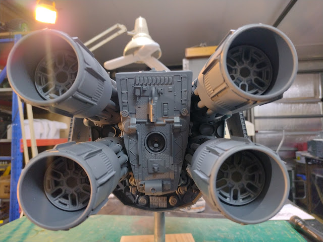
The engines were test fitted to get an idea of how they might look.
They turned out slightly longer than the cylinders in the low poly model but proportionally I think they will be fine.

View attachment 1789210

View attachment 1789211

To maintain the cylindrical nature of the engines in the thumbnail I added pipes coming out of the slots in the PVC vent and terminating on the 45 degree angle of the PVC reducer next in line.
The 8mm solid ABS rod was cut to length and then the angled cut made on the mini chop saw.

View attachment 1789212

View attachment 1789213

View attachment 1789214

The other end of the pipe needed a short flat cut into it to fit between the vent cap and an inner PVC tube.
This was done on the drill press using a small dremel saw disc.
A scrap wood jig was made to hold the angled end of the ABS rod in the correct orientation for machining of the flats.
Two passes had to be made in each of the 40 rods to achieve the required depth of cut.

View attachment 1789215

View attachment 1789216

View attachment 1789217

I then added a small length of tube to each pipe which helped to centre it correctly in the slots and gave it a bit more interest.
There will be more engine detailing to come.

View attachment 1789218

View attachment 1789219

View attachment 1789220

The engines were glued into position and the wiring finalised then tested.

View attachment 1789221

View attachment 1789222

View attachment 1789223

A start has been made on detailing the engine nozzles.
Behind the nozzle is another scrap wood jig to hold the t section evergreen strips vertically and a series of marked lines to align to for the next two strips. The black panels are 1mm styrene sheet with some evergreen textured sheet under them.

View attachment 1789224


Thanks for looking.
More soon...
Beautiful work!!
 
A build like this always has a certain Klingon voice in my head.... 'Impressive'

The scale surprised me a bit as the sketch reminded me of some miniatures game art, but of much a larger ship.

THEN I saw the cockpit...

Am I bad to have a faint longing for some of the holly to have survived?
 
I have nearly completed the detailing on the rear and the engines of the Jan Buragay Spaceship project with a start made on the detailing of the top surface and skinning the sides.


I have also nearly completed the detailing on the front panel. It is going to be a quite heavily nurnied surface.


Thanks for looking.

More soon...
 
I made up the "wings" from 6mm foamed PVC sheet, bent using a heat gun and some scrap wood formers.
The material is oversize and then trimmed back to shape once bent and cooled.


Once happy with the fit and placement I started paneling the surface with 0.5mm styrene and evergreen strips and textured sheet.


I also completed the skinning of the hull with the flat plates of 1.5mm styrene.
The edges were beveled with a sanding stick so the edges meet snugly.

When fitting plates around a protrusion or hole I always fit the hole first with an oversize plate and then trim back the edges afterwards.
It is a lot easier this way than to try and locate a hole in exactly the right place on an already sized plate.
The protruding PVC conduit of the cabin side windows was dealt with in exactly this way and then the PVC sanded flush with the skin after fitting the plate.


Part of the skinning process involved adding a space for a crew door (I have yet to design and make the actual door) and roller style cargo door to each side.


I always try to overlap styrene sheet where possible leaving it oversize and trimming and sanding back flush after drying. It results in a neater seamless join.


Finally just the bottom was left to skin.


Where the angle between plates was shallow I just bent the styrene cold for a stronger result by placing it in a vice along the bend line and gently pushing the styrene over.
Styrene sheet has a side which is more glossy than the other.
This glossy side is due to a thin layer of quite brittle transparent styrene.
I have found if you cold bend styrene sheet away from the gloss side it can split as that brittle layer does not like to stretch.
Bending it with the glossy side to the inside of the bend does not have that effect and it can be bent without stressing the surface.
If you have styrene that has been exposed to sunlight for a period of time it will also become brittle and is much more likely to crack.


I added a couple of tanks made from PVC plumbing parts to each side of the top surface.
This was how I decided to interpret the vague boxy shape thing on top of the ship in the concept sketch.


Thanks for looking.
More soon...
 
Have to jump on what was said above about the engines. Clever design & detailed construction a trademark along with the extra strong armature. You certainly did justice to the stern. Did I see a hidden toggle switch? Yes, kit part recognition. Some of us see these greeblies in our dreams.
 
I decided to tackle the side windows.
I found some PVC conduit that fits inside the larger conduit I made the round ports from that sit at the side of the bridge.
I cut rings of the smaller conduit by parting them off on the mini lathe.
These rings were then stuck to small pieces of 2mm acrylic sheet (perspex).
The acrylic was then carefully sanded flush with the rings and then pushed into the existing larger conduit tube window being careful not to push them all the way through into the cockpit where I would never be able to get them out again.


In the recesses between the hull sections I superglued some of the rubbery tracks from Hasegawa 1/72 Morser Karl kits.
Next I tackled the crew door, knocking up a design in 2D CAD.
This was printed out fullsize onto paper which was cut out and stuck to two layers of 1.5mm styrene temporarily stuck together to make two doors.


I then went to town on detailing the remaining surfaces with many flat panel kit parts, 0.5 styrene panels, evergreen tiles, half circle profile piping and general nurnies.

This was done section by section laying out the largest flat panel parts first and then filling in the gaps with 0.5 styrene and nurnies, rather like doing a jigsaw and getting all the pieces to fit.


To be continued...
 
I added four whip aerials made from some 1.2mm diameter stainless steel fishing trace.
These were suggested by the concept thumbnail.


It was then time to glue on the engine nozzles which had been sprayed with grey primer some time ago.


This brings the construction phase of this project to a conclusion, although the bare bits of PVC pipe, just before the nozzles may need some further attention. I will know for sure when the rest of the surfaces get sprayed with primer which is the next step.

Thanks for looking.
More soon...
 
The grey primer stage has been reached for the Jan Buragay inspired spaceship project.
I masked out where the wings glue on and after spraying the primer attached them with superglue after roughening the mating surfaces with coarse sandpaper.


To be continued...
 
Back
Top