mung
Sr Member
My last project was the Moon Bus and before I completed the painting process on that project I started another RC vehicle project.
After some weeks of closure the charity stores had finally re-opened so I paid them a visit.
I found some more acrylic wine glasses which will be good for the engine bells for a future project and I came a cross a large acrylic pot that I thought might be useful for a rainy day.
It so happened that a rainy day did come ( its winter here in South Western Australia when we get most of our yearly rain).
I had an idea of what to do with this acrylic pot shape.
Once I get an idea everything else is instantly dropped and I feel compelled to follow it up.
This is what I call the experimental phase of a project.
I'm trying to see whether an idea has legs or wheels in this case.
Sometimes the this phase comes to nothing, things don't work out as hoped and the idea is dropped and it never becomes a fully fledged and documented project.
After a rough thumbnail on some scrap paper at work while waiting for a CNC cycle to finish I came up with this tiny germ of an idea for an RC chassis I have on hand.
I had a scrounge through my boxes of shapes and came up with a the dome from a Crayola colour explosion toy.
This is the third one of these I have picked up from charity shops.
It had a matching diameter to the big acrylic pot. I also found a small acrylic bowl which matched the other end of the pot.
A few days later I did some more extremely rough thumbnails with the found shapes in mind.


About a year ago I picked up a chassis of a Kyosho Mad Crusher because it was relatively cheap and I always liked the big solid axles of that particular design.
This old chassis design has been updated over the years and it now has a 5 link suspension system.
The chassis I got didn't have any tyres or wheels or electronics but I had some Imex Jumbo max tyres and wheels from an abandoned project sitting in a box which I figured would fit the bill.

It turned out the old 14mm hex wheels didn't fit and fouled the axles even with the correct Kyosho 14mm adapters so I had to find a set of Hobao 17mm monster pirate wheels which unfortunately have been discontinued.
Lucky for me I think I may have picked up one of the last remaining sets from Taiwan where they were originally made and they fitted perfectly.
This chassis had been sitting around for about a year and I did a number of designs for it but none of them got past the initial idea.
The big acrylic pot find was the catalyst to kick this project into go.
The Mad crusher is pretty wide especially with the wide wheels and tyres I have on it, so the body needs to be wide to suit.
The first thing to do was to cut the shapes in half accurately.
I marked out the centre line with masking tape and carefully cut along the edge with a zona saw.
I bit of sanding on a flat sanding board and the edge is ready to be glued with methylene chloride to the flat 2mm styrene sides of the centre section of the hull.
The bottom of the pot was about 10mm thick so I chain drilled it out and cleaned it up on the belt sander.
Chain drilling is where you drill a series of holes closely spaced and then follow up with a larger size drill which hopefully breaks through the web between each hole thus freeing the section you want to cut out.
Removing the thick portion at the bottom was a vain attempt to reduce some weight of the body always necessary using an off the shelf RC vehicle which is only designed to hold up a lightweight Lexan shell.


All the acrylic to styrene joints were reinforced with some baking soda ( sodium bicarbonate) and thin superglue.

All the styrene joints were reinforced with a narrow strip or doubler.

I made some grills or vents to go inside the little acrylic bowl from 1mm styrene strips sandwiched together with a small evergreen strip spacer between the strips.

Here is the rear section on the just sitting on the chassis.

I took this photo into photoshop to try and come up with a cabin section but didn't have any inspiration so I went back to the shapes box for a further rummage.
I tried out a few things, one of which was a hamster ball but ended up with another couple of small acrylic bowls and decided that arranging them in Princess Leia hairstyle like arrangement was the go.
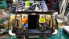
A couple of Bruder figures at 1/16 scale are placed in their eventual location in the cab.
As seems to be my custom there is a central access to the rear of the vehicle.
Here I would usually put a door but decided in this case on steps down to a short hallway behind which I will put a baffle or wall that suggests you can go either left or right just to add a bit more interest.


The last photo I took into photoshop to try out some glazing ideas.
I settled on a relatively simple glasshouse idea shown below.

On the model I have added a couple of recesses underneath at the front for some LED torch headlights and am starting to work on the curved glass house.
I plan to use some thin sheet lexan for this if I can get it to curve without springing back.
I want to be able to remove the front glass while for access to detailing and eventually painting the cabin.
After some weeks of closure the charity stores had finally re-opened so I paid them a visit.
I found some more acrylic wine glasses which will be good for the engine bells for a future project and I came a cross a large acrylic pot that I thought might be useful for a rainy day.
It so happened that a rainy day did come ( its winter here in South Western Australia when we get most of our yearly rain).
I had an idea of what to do with this acrylic pot shape.
Once I get an idea everything else is instantly dropped and I feel compelled to follow it up.
This is what I call the experimental phase of a project.
I'm trying to see whether an idea has legs or wheels in this case.
Sometimes the this phase comes to nothing, things don't work out as hoped and the idea is dropped and it never becomes a fully fledged and documented project.
After a rough thumbnail on some scrap paper at work while waiting for a CNC cycle to finish I came up with this tiny germ of an idea for an RC chassis I have on hand.
|
|
| Initial rough thumbnail. |
I had a scrounge through my boxes of shapes and came up with a the dome from a Crayola colour explosion toy.
This is the third one of these I have picked up from charity shops.
It had a matching diameter to the big acrylic pot. I also found a small acrylic bowl which matched the other end of the pot.
A few days later I did some more extremely rough thumbnails with the found shapes in mind.
About a year ago I picked up a chassis of a Kyosho Mad Crusher because it was relatively cheap and I always liked the big solid axles of that particular design.
This old chassis design has been updated over the years and it now has a 5 link suspension system.
The chassis I got didn't have any tyres or wheels or electronics but I had some Imex Jumbo max tyres and wheels from an abandoned project sitting in a box which I figured would fit the bill.
It turned out the old 14mm hex wheels didn't fit and fouled the axles even with the correct Kyosho 14mm adapters so I had to find a set of Hobao 17mm monster pirate wheels which unfortunately have been discontinued.
Lucky for me I think I may have picked up one of the last remaining sets from Taiwan where they were originally made and they fitted perfectly.
This chassis had been sitting around for about a year and I did a number of designs for it but none of them got past the initial idea.
The big acrylic pot find was the catalyst to kick this project into go.
The Mad crusher is pretty wide especially with the wide wheels and tyres I have on it, so the body needs to be wide to suit.
The first thing to do was to cut the shapes in half accurately.
I marked out the centre line with masking tape and carefully cut along the edge with a zona saw.
I bit of sanding on a flat sanding board and the edge is ready to be glued with methylene chloride to the flat 2mm styrene sides of the centre section of the hull.
The bottom of the pot was about 10mm thick so I chain drilled it out and cleaned it up on the belt sander.
Chain drilling is where you drill a series of holes closely spaced and then follow up with a larger size drill which hopefully breaks through the web between each hole thus freeing the section you want to cut out.
Removing the thick portion at the bottom was a vain attempt to reduce some weight of the body always necessary using an off the shelf RC vehicle which is only designed to hold up a lightweight Lexan shell.
| acrylic pot cut in half. |
| Removing the thick bottom by chain drilling. |
All the acrylic to styrene joints were reinforced with some baking soda ( sodium bicarbonate) and thin superglue.
All the styrene joints were reinforced with a narrow strip or doubler.
I made some grills or vents to go inside the little acrylic bowl from 1mm styrene strips sandwiched together with a small evergreen strip spacer between the strips.
Here is the rear section on the just sitting on the chassis.
I took this photo into photoshop to try and come up with a cabin section but didn't have any inspiration so I went back to the shapes box for a further rummage.
I tried out a few things, one of which was a hamster ball but ended up with another couple of small acrylic bowls and decided that arranging them in Princess Leia hairstyle like arrangement was the go.
A couple of Bruder figures at 1/16 scale are placed in their eventual location in the cab.
As seems to be my custom there is a central access to the rear of the vehicle.
Here I would usually put a door but decided in this case on steps down to a short hallway behind which I will put a baffle or wall that suggests you can go either left or right just to add a bit more interest.
The last photo I took into photoshop to try out some glazing ideas.
I settled on a relatively simple glasshouse idea shown below.
On the model I have added a couple of recesses underneath at the front for some LED torch headlights and am starting to work on the curved glass house.
I plan to use some thin sheet lexan for this if I can get it to curve without springing back.
I want to be able to remove the front glass while for access to detailing and eventually painting the cabin.
Last edited:
")