You are using an out of date browser. It may not display this or other websites correctly.
You should upgrade or use an alternative browser.
You should upgrade or use an alternative browser.
Iron man motorised faceplate electronics tutorial!!!
- Thread starter 7sinzz
- Start date
I've got some issue with the circuit. I followed the instructions and that doesn't seem to work.
I have 3 EMAX ES08D digital servos and 1 TowerPro SG92R servo.
When I try the towerpro with another servo. The towerpro works fine, the other one do nothing. When I try 2 EMAX servos, one is buzzing and the other one does nothing.
I checked each servo alone with the sweep sketch. I even modified the sweep sketch to sweep 2 EMAX servos. That worked. But I can't succeed to make the LED + button + servos work. I used both code (with and without flickering) on the first post.
Do I have to buy analog servos?
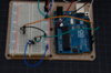
I join 2 pics of the circuit. What have I done wrong?
I have 3 EMAX ES08D digital servos and 1 TowerPro SG92R servo.
When I try the towerpro with another servo. The towerpro works fine, the other one do nothing. When I try 2 EMAX servos, one is buzzing and the other one does nothing.
I checked each servo alone with the sweep sketch. I even modified the sweep sketch to sweep 2 EMAX servos. That worked. But I can't succeed to make the LED + button + servos work. I used both code (with and without flickering) on the first post.
Do I have to buy analog servos?
I join 2 pics of the circuit. What have I done wrong?
Attachments
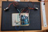
Nothing is wrong with your setup, analog and digital servos works the same way, the only difference is inside them in the servo controller.
Try to feed the servos with a external power source, try a 5V wall adapter a pack of 4 AA batteries or even a Li-Ion pack regulated to 5V and tell me if it works.
For me it is a problem of power feed, the same thing was happening when i tried to feed more than 1 digital servo using the board as the power source.
xl97
Master Member
wheres the power? (battery set-up)
you cant drive/power all that from the Arduino alone..
try powering the Arduino alone from the USB cable.. and using an external battery pack (+6v or less..or whatever your servos are rated for..maybe use a +5v regulator or something) to power the servos (make sure you connect ground from battery pack to BOTH the servos...and Arduino)
I dont see a resistor on that led? (dont burn it out or damage your Arduino)
You only plan on using 1 led per eye? if not... then you need to get some transistors or mosfets to drive yoru array of leds.. (as again..its too much for the Arduino to power by itself)
Oh yeah, I should have mentioned I use the USB cable to power the circuit.
XL: usually I use a resistor jumper for the LED. And as it is a temporary circuit to check if everything's fine, it is not complete (1 or 2 leds with resistor per eye, depends on how I can diffuse the light).
I planned to use 7.4 external power with voltage regulator for servos and resistor for LED.
I've almost read this post completely so I noted every advice you gave...just couldn't understand why my circuit doesn't work.
What I don't understand if the problem is the power feed is that it works when I only sweep the 2 digital servos. Is there a difference from a simple sweep to a button controlled servo?
hey xl97, already finished my tests with the transistors, your post about it, with the schematics using NPN and PNP transistors helped a lot!
Thanks bro")
i used 2 BC548C (NPN transistors, have almost the same specs as the ones you used)

and I'm also using a RF receiver to work as a push button.
Thanks bro
i used 2 BC548C (NPN transistors, have almost the same specs as the ones you used)
and I'm also using a RF receiver to work as a push button.
Last edited:
xl97
Master Member
memebr -
sweet!..
(Im working on adding a BT module to the repulsor pcbs and arc/uni-beam.. so they funation as normal.. but also through BT.. your computer, cell phone or main Arduino ..
this way you can trigger firing/functoins/vib motor while the glove/piece is on the table.. (moving toward a more 'extremis' effect)
DevilFlash - because 1 servo (maybe 2) can be run off the Arduino (barely)... adding more current pull and things wont work..
the Arduino is ONLY capable of supplying a small amount of current per pin..and per board..
I bet even the 1 servo would stop working when it actually has to move or lift something.. (called being under load)..
when a servo is under 'load'... it takes up MORE current than it does when not.. which is more than the Arduino can supply..
(hence you power it from the battery pack and only use the Arduino for the 'control/input/logic' line)
however.. you still need to connect all GND wires (battery pack to Arduino).
even is testing.. use resistors!.. protect your Arduino pins and your components..
Also.. I think you'll be disappointed using only 1-2 leds... I have tried several ways.. less leds means more diffusions.. more diffusion means either thicker piece of semi-trans material (and hence dimmer, not as bright).. or you have to place the leds further away from the piece..which eats up helmet space in from of your eyes!..
*update:
I just looked at memebr's image he posted..
for ALL newbies/beginners here.. THIS is the image/layout I would follow.. and almost mirrors the advice I have been giving all through this thread..
THIS is what I would follow for getting up and started with Arduino and getting ready to port this stuff to its FINAL boards to fit into your end prop (IM buckets)
Arduino UNO (dev board)
breadboard for easy set-up testing of your leds, servo's, switches..etc..
multiple LEDS for eye
using transistor to switch/toggle/pwm eye circuit
two servo's
external battery pack
minus his additional RF control.. this is what "I" would consider the correct, basic approach!..
great job sir! lol
Bring it to the next level..
(personal suggestions only)
I'd get a smaller board.. (nano, pro-min...etc)
no need for a breadboard anymore.. solder servo's directly to battery pack and Arduino pins.
get, make, order some eye circuit pcb's... that hold the leds, resistors and transistor.. (maybe even a voltage regulator based on your specific project)
sweet!..
(Im working on adding a BT module to the repulsor pcbs and arc/uni-beam.. so they funation as normal.. but also through BT.. your computer, cell phone or main Arduino ..
this way you can trigger firing/functoins/vib motor while the glove/piece is on the table.. (moving toward a more 'extremis' effect)
DevilFlash - because 1 servo (maybe 2) can be run off the Arduino (barely)... adding more current pull and things wont work..
the Arduino is ONLY capable of supplying a small amount of current per pin..and per board..
I bet even the 1 servo would stop working when it actually has to move or lift something.. (called being under load)..
when a servo is under 'load'... it takes up MORE current than it does when not.. which is more than the Arduino can supply..
(hence you power it from the battery pack and only use the Arduino for the 'control/input/logic' line)
however.. you still need to connect all GND wires (battery pack to Arduino).
even is testing.. use resistors!
.. protect your Arduino pins and your components..Also.. I think you'll be disappointed using only 1-2 leds... I have tried several ways.. less leds means more diffusions.. more diffusion means either thicker piece of semi-trans material (and hence dimmer, not as bright).. or you have to place the leds further away from the piece..which eats up helmet space in from of your eyes!..
*update:
I just looked at memebr's image he posted..
for ALL newbies/beginners here.. THIS is the image/layout I would follow.. and almost mirrors the advice I have been giving all through this thread..
THIS is what I would follow for getting up and started with Arduino and getting ready to port this stuff to its FINAL boards to fit into your end prop (IM buckets)
Arduino UNO (dev board)
breadboard for easy set-up testing of your leds, servo's, switches..etc..
multiple LEDS for eye
using transistor to switch/toggle/pwm eye circuit
two servo's
external battery pack
minus his additional RF control.. this is what "I" would consider the correct, basic approach!..
great job sir! lol
Bring it to the next level..
(personal suggestions only)
I'd get a smaller board.. (nano, pro-min...etc)
no need for a breadboard anymore.. solder servo's directly to battery pack and Arduino pins.
get, make, order some eye circuit pcb's... that hold the leds, resistors and transistor.. (maybe even a voltage regulator based on your specific project)
Last edited by a moderator:
Thanks ^^
I already have a Arduino Pro-Mini (sparkfun) waiting to the final assembly, but i'm using the UNO just to test stuff,
the circuit is regulated to 5V with a LM7805 Vreg, also already made the PCB blue print for the transistors/LEDs/resistors and for the PCB that will hold the voltage regulator, LEDs and servo and battery pack plugs, all i need to do now is send it to a place to make em for me.
Djstorm100
Active Member
The button is connected to nothing, there is your problem.
the pin 2 from the arduino is going diretcly to the GND, passing through the resistor
turn the button 45º and you will be fine.
Arduino is a open source platform for small automations, so the material to get started and learn how it works and how to code on it is also free, if you search the web you can find pretty good material.
The price on the arduino rev 3 board does not change much, so you can grab it from radioshack,
the components kit (the pack1) is a lil bit expensive, you can grab what you will need separately, cause you will use almost nothing from that ultra inflated 99.00 bucks kit.
So, just buy a strip of 10K and 330 ohms resistors, a couple of push button normally open, a couple of leds, a breadboard, some breadboard wires and you are set to go.
The servo from radioshack is not the one you need, this one on the link is modified to continuous spin, its great for robots that will use wheels, but not good for what you need, try to find a non modded servo, the MG955 is a great servo for this project, if you wanna open a lil bit more that wallet you also can buy 2 digital servos.
What watt am I suppose to use?
Djstorm100
Active Member
Sorry dude, i don't get it, what you mean?
Sorry buddy...Resistor come in different watts 1/8 1/2 1/4 watt. I'm at radio shack now
Last edited:
Djstorm100
Active Member
I use 1/4 ones just but all should work fine..
but all should work..
When does watts become a concern? (trying to learn here lol)
xl97
Master Member
it really depends on the application..
here this can explain it better than I can:
How do you determine a resistor's wattage
lol
here this can explain it better than I can:
How do you determine a resistor's wattage
lol
Similar threads
- Replies
- 1
- Views
- 309
- Replies
- 1
- Views
- 452
- Replies
- 2
- Views
- 540