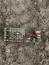
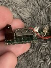
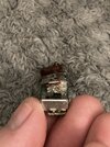
Cave Scene - Tom tries to make a circuit

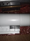
Sooooo, the snap switch needs to be affixed to something solid in order for this to work. I drilled a beautiful small hole through the board around the wires/resistor area and just kept pushing the switch around down there :rolleyes:

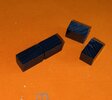
Anyway, I also finally did the buttons. I used a coping saw to rip through it, and a dremel to straighten the cut. Coping saws are not easy to keep level, and my xacto razor saw had worn out. (see, this is why I want to invest in a small table saw or miter saw... any recommendations?)

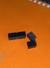
I cut one long piece and separated it front, top and bottom to give the look of two buttons... since we still don't know what's up with them and it will reduce headaches when glueing. I tried to cut two pieces again and screwed them up anyway! The buttons I ended up with are exactly uneven like the original prop. Pic to come
Here they are flipped one way,
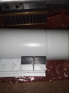
20210706_164321.jpg

And then the other
20210706_164331.jpg

Anyway, delrin is self lubricating when you cut it (I think) but it's also really hard. The surface has these layers or patterns in it, and they're hard to get out. The real prop buttons look like one glossy surface, so this is another test to see if the Delrin theory works. In comes my trusty metal files. I have some that are very fine, and well worn out. I used them, and it felt like nothing was happening.. until I looked at it. The patterns became blunter looking and shrunk the more I used the files.... until...
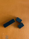
J6MANBl+S+GRjwPpgx9pwA.jpgfullsizeoutput_296b.jpeg

I used baking soda and dawn dish soap to really burnish the surface too.
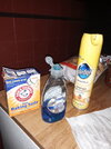
20210706_165200.jpg
it's so smooth and the edges are razor sharp!!! So I rubbed it with pledge furniture wax as a final thing.
Speaking of that, I drilled two holes for glue to gather and help grip the buttons themselves, and scratched the saber for good measure
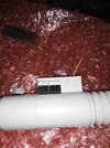
20210706_163244.jpgI6dz3%CkRiiH7z72gyo8Qw.jpgyXeegy9OTYmx2Yj35Py5TA.jpg

Squished some E6000 on there... and I really had to push them down, and trim the excess which scratched up the face of the box... still have to get those out somehow.
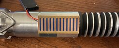
fullsizeoutput_2973.jpegfullsizeoutput_2974.jpegfullsizeoutput_2975.jpeg

the 1/4 by 1/4 Delrin was not a perfect square either, so I positioned the stock like the prop.. a little wider than it was tall. Not half bad!
 
Last edited:
Okay, I’m back at this with newer information. I’m doing fiber optics…

This was SO annoying, but I used my uncles very fine needle files from his machinist classes in the 80s. The corners of the triangles are the exact angles of the triangular file of that set

I need to upload a pic with light
IMG_1477.jpeg
IMG_1478.jpeg
IMG_1479.jpeg
 
Okay - so I’m attempting to complete a newer observation I broke my 785 board. Now what?

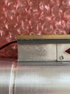
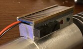
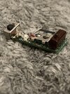
Well, it was a good opportunity to go ahead and do what I thought should have been done in the first place. I used a snap switch like the one in the Boba Fett helmet and affixed the board back together using that as a connection.

I was then able to dremel a little divot into the bottom of the left side plate and dab a tiny bit of E6000 onto the switch and then a bunch on the back. Effectively allowing it to click up and down but stay put!
IMG_1529.jpeg
IMG_1532.jpeg
IMG_1536.jpeg


Also I used the frame of a DaveP brass thingy to anchor the rear two plates.

IMG_1530.jpeg
IMG_1532.jpeg

It’s messy I know. This wire… literally is like hair, I had a ball of it from another member here and it’s basically fly wire, twice as small as the smallest 21/22 stripper hole on my pliers. Soldering it and getting it to stay put, even with helping hands, was so very frustrating. I opted to make sure the connection was solid over looking pretty
IMG_1531.jpeg
IMG_1526.jpeg
IMG_1525.jpeg
IMG_1524.jpeg
IMG_1522.jpeg
IMG_1518.jpeg
IMG_1517.jpeg
 
Oh god, I’ll write more in a bit but my back and neck are sore (I have c dystonia and TOS ) and this is MICRO work! I had to focus hard. The wires and contacts are smaller than a bead of solder.

I used fly wire for the red wire and then I stripped a whole orange one for the bare silver wires. I wrapped it and soldered it where I could tell there was “something” … and then left with excess wire I could kind of tell where it went next. I also could tell where some of the Death Star brass was tarnished, because I soldered mine to the board instead of using glue.

It’s not a direct replica but it really is very close and serves the purpose of each kind of decoration. Thank you to DaveP for the brass stuff, I chopped it up and re-shuffled it to what my eyes were seeing. I didn’t do the white **** on the chip… back and forth on that. The chip brass was the only place I used superglue.. oh and to situate the wrapped red wires in their hole!

Guess what.. I can click the switch by pressing on the plate with the wire soldered to it. thanks to E6000 on the back. Still no idea what they did
IMG_1546.jpeg
IMG_1548.jpeg
IMG_1538.jpeg
IMG_1539.jpeg
IMG_1543.jpeg
IMG_1544.jpeg
 
I successfully made a circuit!

Okay to preface, I had to re-do these connections multiple times. I don’t inherently know why, but I was trying to make the connections stable (they’re a smaller than pocket lint) and I used solder braid to re do them. That can sometimes charr the fiberglass. I can solder fine but.. it just looks a mess lol

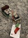
CR1025 battery, 3V and two fast blinking LEDs. Pretty primitive. Used an old SPDT switch that I swear I’ve seen in Star Wars and I cut the toggle switch to match what I see. Unfortunately when I tried to re-do a connection I kinda melted the plastic lol
IMG_1690.jpegIMG_1689.jpegIMG_1686.jpeg
It works though!
IMG_1693.jpegIMG_1692.jpegIMG_1691.jpeg
 
Thank you! It appears with the "fake" Casio board on top, it traps more light from the LEDs, making the flashing brighter. I thought I would have to isolate each LED and point them towards the acrylic I made but it doesnt seem to be a problem, I'm not seeing both arrows light up
 
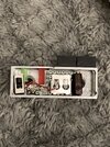
Okay this is an interesting update. My panel or circuit was working but every time I put it in the box it would flicker and turn on! The metal box touching the solder dots on the back of the board was completing the circuit.

So I didn’t go out and buy circuit masking fluid. I first tried to coat it in polyurethane - still didn’t work, not sure why.

Instead I cut some VERY thin model styrene, almost like cardstock, and essentially vacuformed it over the back. I heated it until it was curling up and I pressed the soft plastic into the board. For good measure I ran a droplet of super glue around the perimeter.
IMG_1956.jpeg
IMG_1957.jpeg
 
Wicked clean Tom! I like it!
Thank you!

Unfortunately, the snap switch was still too high in the box. Tried to shave the top down and broke it.

And then something was up with the battery contact, it needed to be squeezed to work, maybe I need one without the plastic drawer.

Anyway, back to the drawing board… but I have really good ideas now about how to move forward lol
 
Okay folks, my last one.. some of the connections snapped and it was still too thick. I ordered more parts from China and tried AGAIN.

Trial #1 was an experiment and I definitely snapped the board and stuff, but it gave me great ideas.

Trial #2, all seriousness, I snipped up a shiny piece of metal sheet I kept from some electronic thing I ripped apart. It is very shiny and springy, I’m guessing steel, but it takes solder really well and transfers electricity!
IMG_2230.jpeg
IMG_2231.jpeg


What this allowed was for me to sandwich a CR1025 at the same plane as the board. This helped immensely with the height issues inside the box.
IMG_2240.jpeg
IMG_2250.jpeg


You’ll notice I also laid the LEDs sideways and filed them flat, essentially getting everything to 5 ish mm height I think.

My idea now is to stick whatever tool through the LC785 board and push the lever of the snap switch sideways, simulating the movement in the deleted scene. I know this isn’t accurate but I’m up to my eyeballs here lol

I cut some styrene to lay on the bottom but failed in heating it to fit and stay, I’ll coat the bottom with something but I need a break

I’m going to upload a clip to YouTube and link it here
 

Your message may be considered spam for the following reasons:

If you wish to reply despite these issues, check the box below before replying.
Be aware that malicious compliance may result in more severe penalties.
Back
Top