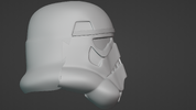
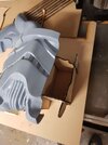
ANH Stormtrooper Helmet Build (From Scratch)

TheDragon

New Member
Since the beginning of this year I had a harebrained idea to build a vacuum forming machine, which lead me down the rabbit hole of star wars helmets and now to having begun sculpting moulds to produce a stunt tk helmet. I am wanting to eventually use polypropylene to form it with the intention of making an "as close to" screen accurate helmet as I can get and make a bust to display with it (chestplate etc.).

January-ish I started planning my vacuum forming machine in solidworks and was able to build it mid February and did a lot of testing to get it working right (still have a ways to go) but as uni started up again have less time to get into the garage and tinker with it as well as run around and get supplies.

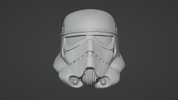
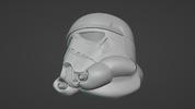
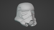
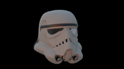
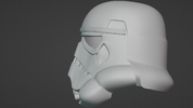
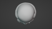
So far I have modelled the faceplate and begun on the rear of it but was eager to finish the faceplate before moving onto the rest. I'm a self taught 3D modeller and use the freeware Blender to do all my work but found it's just as powerful as any other programs out there. My plan is to get all the main features of the helmet out in my model and to sculpt all the bumps and marking inside the traps afterwards.

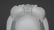
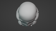
I was looking for guidance on where my model isn't correct in comparison to one of the original faceplates (as much scrutiny as possible) and where to look out for going into the next stage of adding the minor details like the bump on the dome etc. I'm mainly interested in the faceplate at the moment, and haven't finished the back as you'll tell straight away it's missing the rear traps. I am also struggling with the depth of the eyes, front traps and indents the hovi mix pieces go into as I don't have a lineage helmet to compare it too as well as the fact that the model is like 1cm in width which i'll have to scale appropriately later on.

I also have a resin printer and will eventually make the moulds with that which will hopefully capture all the details in the model.

I think that's enough yapping on my behalf though and if you have gotten this far down the page thank you and if you wanted to know anything more just ask as I'm not sure If I covered everything in this post.

Below I have attached some images as well as one rendered image where I show off my bad rendering skills. If you needed any additional angles please ask as well, or to remove something like the brow or hovi mix's from around the model to see what's under it.
 

Attachments

  • Front.png
    Front.png
    1.6 MB · Views: 125
  • UnderRight.png
    UnderRight.png
    1.6 MB · Views: 97
  • Underneath 1.png
    Underneath 1.png
    1.8 MB · Views: 79
  • TopDown.png
    TopDown.png
    1.5 MB · Views: 81
  • Side.png
    Side.png
    1.6 MB · Views: 82
  • Screenshot 2024-04-01 004000.png
    Screenshot 2024-04-01 004000.png
    646.3 KB · Views: 84
  • RightSide.png
    RightSide.png
    1.6 MB · Views: 77
  • RealTop.png
    RealTop.png
    1.5 MB · Views: 74
  • LeftSide.png
    LeftSide.png
    1.6 MB · Views: 99
Last edited:
I have made a few changes to the faceplate model since the last post, it's not perfect but unless I had a lineage helmet to compare to I don't think I can do much better. For that same reason I decided not to include the various warts on the faceplate in the print. For reference here is a few images of the faceplate prior to making the mould from it (I'll explain my mould making process further down).
untitled.png

The above photo has my sample tear indentation in it, which used a displacement map so that I could edit it without ruining the ability to easily manipulate the geometry of the faceplate.

And here a photo of it with my WIP ear and rest of helmet:
KhakiWEar.png


Once again asking for feedback (or good photo reference), but this time on the left ear, as It will be the next on the list to print due to its ease to do so. I'll post more on the ear at a later point in time.

Once I was satisfied with the model I began constructing the mould from a algorithmically altered version of the faceplate model out of resin.

As my resin printer isn't big enough to print the faceplate in one go I made it in 3 parts and designed a mdf support structure to give the mould more rigidity without increasing print time, part size and to align the parts properly.


20240412_195503.jpg

Above is the 3 Parts of the faceplate out of the printer, notice the right most piece is missing a chunk, thats as the rest exceeded my printers build height. Some of the supports still haven't been properly removed.

20240413_175402.jpg

Above is the Internal laser cut support I made on my DIY cnc mill turned laser cutter (It requires a lot of effort to not go blind whilst using). I attached an additional picture to this post.

20240413_180410.jpg

Finally above is the rough assembly of the mould, Note the lower end on either side of the vocoder is all wrong, this is a mistake I'm still kicking myself over and i'll need to spend a long time sanding out.

I had problems in vacuum forming R2 parts with the seams showing in the final part which I believe is caused by different materials responding differently to the heat of the plastic (contracting at different rates), to remedy this I'll use UV resin and hand cure it with a UV torch as a means to use 1 material for the whole mould to hopefully prevent this from happening on the part. Worst case scenario, I make a mould of the resin version and cast it in a different material.

The mould Is far from finished but I just wanted to make an update as I wanted to keep a somewhat consistent record of this project. Once I get more time I'll do the most fun part of sanding the mould!

Also If anybody has been down this road before advice would be great.
 

Attachments

  • 20240413_175629.jpg
    20240413_175629.jpg
    364.1 KB · Views: 50
Last edited:
It's been almost a month since I posted last, but wanted some real progress before adding to the thread. As of now I have a polypropylene faceplate formed and more work to do to the die needing to be done before making some helmets in the right colour. Below is the steps in which I took to finish the die to get to the finished faceplate:

Before I continue, If anyone has photos of what the ear dies looked like or images of ear moulds that produce screen accurate ears it would be greatly appreciated as I spent weeks sanding the faceplate due to inconsistencies with the model vs the die and would rather get it right straight off the printer to avoid warping a mould made of different materials in the vac forming process.

Screenshot 2024-04-30 023318.png

This is so far the 3D model of the helmet, note changes have been made to the real world counterpart of the faceplate that have not been adjusted on the 3D model. The ears have proven to be a real challenge to model, both topology-wise and in sourcing good images of but mostly happy with everything but the ear bars.

20240413_181236.jpg


I initially used JB superweld to glue the printed sections together in which I thought would work great but proved not to be and intervention with baking soda took place. This left much to be desired in terms of seam lines which then needed to be sanded out.

20240414_155112.jpg


I briefly touched on the support created below the mould in the last post, here is a better shot of it. The support both ensures that the mould doesn't bend in ways it shouldn't under vacuum and to allow air to travel through the mould without having to drill long holes through a brick of material.

20240421_040110.jpg


Here is a shot I took of my mould next to my AM helmet (not sure which version). The markings on the mould indicate what needs to be sanded or filled and by how much. The measurements from my helmet were never sourced from the AM helmet, as even though its a fantastic kit I wanted to ensure I was using only lineage reference.

20240426_141316.jpg


Here is a shot of the helmet after receiving a coat of body filler.

20240430_162007.jpg
20240430_162013.jpg


These two shots are of tamiya modelling putty used to clean up any undesired lumps or grooves in the die.

20240506_160533.jpg


Above is a photo of the first polypropylene faceplate, behind it the second. And below, a trimmed faceplate with resin printed hovi tips which are to be further improved upon.

20240506_192556.jpg


What I did notice from the polypropylene was that there are a lot of bumps on the faceplates that were absent from the mould which I am attributing to the plastic itself and the way it forms. If this is indeed the case, It was probably for the better that I didn't add these bumps to the mould itself as forming the polypropylene over an already bumpy mould would probably exaggerate the bumps in a way that it was never like on the screen used helmets.

As mentioned at the beginning, I am now moving onto the back cap before revisiting the faceplate in the future to fix the now obvious inaccuracies that I caught in the formed faceplates and to add the ovals in the traps which I decided should be on my mould. As well as this major alterations need to be made to the fairing on the die due to difficulty in removing the faceplate from it as well as possibly a complete overhaul of my vacuum forming machine.
 
Last edited:
I missed this the first time round. You’ve done a fantastic job getting the ANH look down. Well done!! Impressive way to make a mold also.
 
cool thread.
something in the chin and mouth area looks off to me at first looks. and the eyes seem to be a little large. or close together. or something.
could be the photos or could be something isnt aligned correctly.
the proportions seem a little large in relation to eachother.. the feel i get from a stormtrooper helmet is the compactness of
the elements.
the shape is there.. would love to see the references you are using too.
keep it up. theres a lot of work in this thread.
you sure picked a difficult design in the TK.
Thanks for the advice, I'm currently in the process of building a new vacuum former (which I might post more on here) but have been marking up areas of the faceplate to change once thats done. I have noticed the chin looks off, as do the corners of the mouth. I think the problem is that the space underneath the eyes, as it moves off to the teeth doesnt have the correct curvature and is throwing the whole thing off. I reckon a combination of this and my crappy photography exaggerates it.


My plan is to do a full resculpt eventually once I get a better workflow for using perspective images to model. As for reference, Im using anything that I can get my hands on that has metadata built in as I need that to setup a digital camera to project into the scene. But have made sure everything is of original helmets or with direct lineage (e.g RS helmets). I'll send the folder of my reference photos at some point but will have to refind where i got them so I can properly credit everyone.

When I make my next post I'll include some orthographic views and measurements of both the 3D model and sculpt, which differ for each other now, so that you can make better comparison. The initial digital screenshots in this thread had a focal length of 100mm which has a big impact on how the model looks and was a mistake on my behalf.

I've got a handful of weeks left before break and hoping to make a lot of progress over the holiday period.
 
Last edited:
I've had a little bit of time to work on my new thermoformer design in which will make up majority of this post. But first, here's a semi-painted version of the first iteration of my helmet mould done a few days after the last post...

1718108749330.png
1718108767745.png

Painting it made it clear that the helmet sits in the uncanny valley between the film used and rubies deluxe so I've decided to start again from scratch in that regard as I also wanted to improve on mould design to reduce undercuts which will hopefully improve demoulding the helmet as the two faceplates that I did form ended up being impossible to remove. I was also thinking about possibly doing a hero helmet instead as it is a pain to paint the polypropylene, if I was going to start again from the ground up.

Thermoformer Design

I started designing what will hopefully be my new thermoformer, as what I currently have lacks in heating and usability which I aim to fix in this new design. The thermoformer was constrained to the following criteria:
  • Must be able to evenly heat the plastic sheet to forming temperature.
  • Must be able to be run-on single-phase power.
  • Heater must not be close enough to the mould in which to cause damage via heat to it (3D printed moulds).
  • Must have a plastic sheet input size of 600x600mm.
I am using the vacuum pump from my previous setup, being a 9 CFM pump, with a 70L tank to store vacuum though will need to rearrange how that is setup.

To heat the plastic I was wanting to use 12x 250W RS PRO Enclosed Quartz Infrared Heating Elements wired in parallel and connected to two separate outlets to keep within the 2400 watts my outlets are able to output. I'm not sure if this is the safest or best strategy for doing this but will consult an electrician before going forward.

The layout in which these heating elements will follow is as pictured below:

Screenshot 2024-06-11 220925.png

With the Quartz elements having a 20mm PTFE spacer between them and the main sheet in which they are attached to.

To improve usability over my past design, I redesigned the way in which plastic is clamped down, now using 32x20mm aluminium angle and 4001 toggle clamps from amazon:

Screenshot 2024-06-11 221306.png

This frame will have Delrin V-wheels on the edges to allow for it to slide up and down with ease as my current design suffers as it's hard to align the frame over the platen when the plastic is dropped onto the platen (As I designed it to maximise platen size).

Screenshot 2024-06-11 221714.png

Note: this only includes everything associated with heating and the plastic clamp.​

Above is the design as It currently looks, I've used 20x20 aluminum extrusion to make up the frame to allow for the v-wheels to slide on as well, as because my current welded design wasn't accurate dimensionally due to warping after welding the steel on the mig.

Finally, I was undecided to whether to use a single hole in the center of the platen, with the platen itself having a slight incline towards the center or a grid of holes over the entire surface.

I wanted to go over the design of the thermoformer before building it incase anybody can see any issues with it before I spend an arm and a leg building it or anything I could possibly improve on. Any feedback is appreciated.

More to come hopefully in the next weeks.
 
Last edited:
I've spent the last week reworking my model for the cap of the helmet, which I believe is the same for both the stunt and hero helmets, and it's currently looking like this:

Screenshot 2024-06-25 144629.png
Screenshot 2024-06-25 144746.png
Screenshot 2024-06-25 144802.png

I realised that I had exaggerated its features, much like the faceplate, so pretty much re-modelled it. I also had issues adding the traps in the old design due to how it was constructed and as you can see was able to fix that in the new version by starting with the traps before working on the rest of the cap. I also randomized some of the vertices on the more planar surfaces to try to give it a clay sculpted look, much like the originals but not sure if I'm happy with it.

Below is version 1 compared to 2
Screenshot 2024-06-25 144531.png


I was starting work on the hero faceplate as well, and was wondering if anyone knew whether it was true that the hero helmets eyes were "free formed" as Ainsworth claims as I've heard he isn't the most reliable source, if that were true I was also wondering what a mould like that would look like.
 
Since the last post, I've been working on the ears. Below is the current iteration of them.
EarsRev4.png

I started with the stunt ear caps made previously but realised quickly that the topology was less than ideal and made it difficult to easily adapt, leading to this new design. Everything that was in the stunt ear was adapted over to the hero but smoothed out to an extent, obviously having 3 bars instead of 4 as well.
EarsRev4Wireframe.png


I however am still struggling to get the bumps looking right, as you can see in the close up below.
LeftEarClose.png
RightEarClose.png


The reference I found of the Original Hero helmets showed that the ear bumps were crooked on the right side so I've mimicked that in my design (See Below).

1720278312492.png

Image taken from starwarshelmets.com
There is more work to be done on the ears before I am happy with them but I just wanted to share an update on my progress so far. I'll make a dedicated post to the faceplate once it too is close to completion as the lower chin and vocoder are yet to be finished.
 
Last edited:
I'm Jumping the gun a bit with this post but wanted to share some photos of the helmet model as it is right now. There is still work to be done to finish the teeth, traps, ears and bubble lenses before I start turning the meshes into moulds.

1720812596372.png

The modelling of the faceplate used a lot of reference from the photos of the recently auctioned hero armour and helmet as well as the RS helmet made a few years back. I started with a rejigged version of my stunt mixed with the battlefront rotj mk2 helmet and aligned it to the reference of the hero faceplate to try to get it as close as I could though made up the underside from scratch due to lack of good reference. I also put the bumps in the front traps this time round that I omitted from the iteration of the stunt I first posted here (stunt helmet with warts to come).

Render Awmark.png

I roughly painted up the model to render a few nice images (Excuse the shoddy pinstripes). I'm learning a new software for 3D painting which I will hopefully use in the future to put make a stunt with warts using displacement (as i mentioned a few months back).

Render Bwmark.png

I have accumulated a list of differences between the stunt and hero faceplates and will make a more detailed post in the future however I am going to take a step back from this project for a while as after 4 months of mostly 3D modelling I've lost interest in potentially another x months sanding and filling moulds. In Saying that, I will be posting my latest stunt faceplate here in the next weeks to which fixes the problems of the crevices being too shallow and features being too geometrically perfect in the previous attempt.
 

Your message may be considered spam for the following reasons:

If you wish to reply despite these issues, check the box below before replying.
Be aware that malicious compliance may result in more severe penalties.
Back
Top