Adruino Help for B9 Robot (1960)s Sound plusing light

MB Trooper

Active Member
Hello RPF.

I am looking for help on creating from Arduino LED lights that will pulse with the sound files that I have for my B9 robot costume from the original 1960s Lost in Space. I am making B9 as a wearable costume and this is one of the very important parts of the robot.
B9.jpg


I have never done anything in Arduino before so I am probably not starting with the easiest thing to do but this is what I need.
So when B9 specks his Neon lights up to the sound of his voice. I have a sound board on my tablet and I have the sound files for his iconic saying I just need to be able to get an LED strip to flash to the sound files.

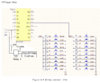
I have bough a Arduino starter kit, an LED strip and a sound sensing module. A friend of mine sent me this link to a u-tube video on how to make LED lights pulse on a breadboard.

aaa.jpg


I am wondering if the code will work with an LED stripe. As well I need to have the 5V port for the sound sensor and LED strip. Can I just plug the 5V from the UNO into the negative row on the breadboard and plug in the wire for the sound sensor and the LED strip to this?


PROGRAM:


int DO = 2; //Pin for Digital Output - DO
int AO = A0; // Pin for Analog Output - AO
int threshold = 523; //Set minimum threshold for LED lit
int sensorvalue = 0;

void setup() {
Serial.begin(9600);
pinMode(8, OUTPUT);
pinMode(9, OUTPUT);
pinMode(10, OUTPUT);
pinMode(11, OUTPUT);
pinMode(12, OUTPUT);

}
void loop() {
sensorvalue = analogRead(A0); //Read the analog value
Serial.print("Analog: ");
Serial.print(sensorvalue); //Print the analog value
Serial.print(" ");
Serial.print("Digital: ");
Serial.println(digitalRead(DO)); //Print the digital value
if (sensorvalue >= threshold) { //Compare analog value with threshold
digitalWrite(8, HIGH);
digitalWrite(9, HIGH);
digitalWrite(10, HIGH);
digitalWrite(11, HIGH);
digitalWrite(12, HIGH);
}
else {
digitalWrite(8, LOW);
digitalWrite(9, LOW);
digitalWrite(10, LOW);
digitalWrite(11, LOW);
digitalWrite(12, LOW);
}

}

Sorry for stupid questions this is totally out of my wheel house.

Thanks for any help on this.
 
Last edited:
Have a look at this: scottlawsonbc/audio-reactive-led-strip

it uses a raspberry pi rather than arduino but they’re not too expensive and I think it might achieve what you want.

edit: you might not even need a raspberry pi, just an esp8266 - whcih is just like an arduino with built in wifi & bluetooth.
 
Last edited:
Wouldn't it be simpler to just use an mp3 player driving a FET transistor since you only need one color, not RGB and the code to control it.
What is being show in the youtube clip in the previous post are "NeoPixels" (addressable LEDs), a little overkill for your project, unless I'm missing something. Here is what I did for my 1/6 scale B-9, is this close to what you are trying to do?

Thanks for the reply and yes I'm sure that would work well but like I said electronics are out of my comfort zone. I googled what an FET transistor is but I would have no idea how to hook it up to an MP3 player and lights.
 
Another even easier option is a small board running something like ‘xlights’ Connect it to a string of lights and configure from your phone over wifi. Lots of beginner tutorials out there. Cheap and easy, there’s only 3 wires (+ve, gnd data) no messing about with code. Download link <—

search for how-tos on seasonal lighting - you’ve only got a few lights compared to hundreds but the principal is the same.
 
My first question is.. will that sensor be enough?

I have played around with one before.. and it didnt seem to pick up 'noise' very well..

Anyways..

The detection of the 'noise' is the first (and most important) step here..

Do you have the Arduino IDE all set-up/installed on your PC? and can you upload code to your Arduino yet? (ie: you can successfully upload the default BLINK sketch to the Arduino?)


If so..

Maybe try these example sketches (code)

Both a DIGITAL & ANALOG example:

Code:
//Digital Example:
int ledPin = 13 ;// define LED Interface
int digitalPin = 3; // define D0 Sensor Interface
int val = 0;// define numeric variables val
 
void setup (){
    pinMode(ledPin, OUTPUT) ;// define LED as output interface
    pinMode(digitalPin, INPUT) ;// output interface D0 is defined sensor
}
 
void loop (){
    val = digitalRead(digitalPin);// digital interface will be assigned a value of pin 3 to read val
    if(val == HIGH){ // When the sound detection module detects a signal, LED flashes
        digitalWrite(ledPin, HIGH);
    }else{
        digitalWrite(ledPin, LOW);
    }
}


----

//Analog Example:
int analogPin = A0; // select the input pin for the potentiometer
int ledPin = 13; // select the pin for the LED
int sensorValue = 0; // variable to store the value coming from the sensor
 
void setup () {
    pinMode (ledPin, OUTPUT);
    Serial.begin (9600);
}
 
void loop () {
    sensorValue = analogRead(analogPin);
    Serial.println (sensorValue, DEC);
    
    //if sensor goes above threshold
    if(sensorValue > 200){
        digitalWrite(ledPin, HIGH);
        delay (1000);
    }
    //switch off LED
    digitalWrite(ledPin, LOW);
    delay (1000);
}


At least here.. you can tighten up HOW you want to detect the sound (how sensitive it is..etc..etc)

At that point, you can do whatever 'led' effects you want..


Some tips:

* You probably CAN NOT power the Neopixel strip directly form the Arduino board (not from the +5v pins..etc).. but this depend son how many LEDS you are using.. you -might- be able to get away with 1 or 2? but not more. (You'll burn out your Arduino)..

Power will need to be from a REGULATED +5v source.. with enough current for however many LEDS you are using.


When you get to actually triggering the lighting effects.. you'll need to expand more on what you mean by this:

"LED strip to flash to the sound files"
&
"LED lights pulse"

detecting the event that will trigger this action/behavior is first.
 
My first question is.. will that sensor be enough?

I have played around with one before.. and it didnt seem to pick up 'noise' very well..

Anyways..

The detection of the 'noise' is the first (and most important) step here..

Do you have the Arduino IDE all set-up/installed on your PC? and can you upload code to your Arduino yet? (ie: you can successfully upload the default BLINK sketch to the Arduino?)


If so..

Maybe try these example sketches (code)

Thank you. I will give this a try. I only need one strip of LED lights so I think 5V should be enough.
 
You are confusing voltage and current. :)

The Neopixels -require- 5v (no way around it)...

The Arduino also work at +5v... (no way around it.. unless you are using a specific +3.3v version of an Arduino board....but again, not the same)

However any given Arduino I/O pin can ONLY (max) deliver around 40mA so maybe 1 led.. or 2 max.. for a Neopixel.. thats 20mA PER COLOR.. so 60mA total if you are trying to do 'white'.. for example.

The whole Arduino (chip) can only provide 150mA-200mA in total!.. not enough to power your Neopixel strip..

The regulator (+5v pin) will depend on the regulator of the Arduino model you use.. but roughly 500mA or so.

I dont think enough to power your strip.

Using the above code.. you do NOT attach the Neopixel strip at all.. it will use the on-board LED (pin 13).... this is just to test sensitivity..etc.. and reliability.
 
Last edited:
However any given Arduino I/O pin can ONLY (max) deliver around 40mA so maybe 1 led.. or 2 max.. for a Neopixel.. thats 20mA PER COLOR.. so 60mA total if you are trying to do 'white'.. for example.

I think you're getting confused, the first NeoPixels "data in" should be the only line getting connected to the Arduinos I/O pin, not their VCC pins, they should be on it's own buss and powered from the 5 volts directly.
 
I must have missed the part where MB Trooper talked about a sound activated switch, I thought he wanted to just produce the voice controlled
illumination using LEDs, similar to this effect.

 
I think you're getting confused, the first NeoPixels "data in" should be the only line getting connected to the Arduinos I/O pin, not their VCC pins, they should be on it's own buss and powered from the 5 volts directly.

Then you must be addressing the wrong person.

What makes you think I"m confused? (because I broke down the total current available on any given I/O pin.. -----AS WELL AS----- the total current output from the regulator???... All in support of NOT powering from the +5v pin form the Arduino.. but a direct, dedicated, regulated +5v source.)

And what part of my comment alludes to anything different than what you just regurgitated?

My comment was in response to this:

"Thank you. I will give this a try. I only need one strip of LED lights so I think 5V should be enough. "

Where the OP says they will be powering it from the +5v PIN on the Arduino.


on it's own buss and powered from the 5 volts directly.

Hmm.. what +5v bus would this be? Are you referring to the +5v pin on the Arduino?

What Arduino type? UNO? In your mind what is the max current output for that linear regulator? around 500mA or so?

SO if OP does fill color?... what around 10 leds tops? I'll doubel down on my previous statement.. I dont believe that will be enough current to power your STRIP.


How many LEDs in total? 20 then?

Single color? Mix? full brightness? plan for max of course..

20led x 60mA = 1.2A still taking that from the regulator? :)
 
Last edited:
Then you must be addressing the wrong person.

What makes you think I"m confused? (because I broke down the total current available on any given I/O pin.. -----AS WELL AS----- the total current output from the regulator???... All in support of NOT powering from the +5v pin form the Arduino.. but a direct, dedicated, regulated +5v source.)

And what part of my comment alludes to anything different than what you just regurgitated?

My comment was in response to this:

"Thank you. I will give this a try. I only need one strip of LED lights so I think 5V should be enough. "

Where the OP says they will be powering it from the +5v PIN on the Arduino.


Hmm.. what +5v bus would this be? Are you referring to the +5v pin on the Arduino?

What Arduino type? UNO? In your mind what is the max current output for that linear regulator? around 500mA or so?

SO if OP does fill color?... what around 10 leds tops? I'll doubel down on my previous statement.. I dont believe that will be enough current to power your STRIP.


How many LEDs in total? 20 then?

Single color? Mix? full brightness? plan for max of course..

20led x 60mA = 1.2A still taking that from the regulator? :)

I'm very sorry if I offended you, that was not my intent, I was just thinking of how easily someone would be confused with the phrase "I/O pin" when talking about power, it would be better to refer to them as "power pins", would hate to have someone using a different board actually attach to one of the I/O pins and fry the board. The explanation was just a bit confusing for someone who doesn't normally work with these. Again, I'm very sorry if you took what I said the wrong way, I could have worded it better....:(
 
I could have as well! :) No worries! (I was curious as to what parts were misleading for you.... I should have used some emojis!) ;)

I outlined the I/O pin current restrictions as well as the regulator current limits to try and outline why the OP needs to do exactly as you say, use a direct (regulated/stable) +5v source/bus.... and to give some general background on things, because the response about voltage when it was a reference on current felt like some background was needed.

* The I/O pins cant handle it. (current)
* and without more input on the use of the strip (colors/brightness/animation), that the +5v pin on the Arduino (regulator) probably cant handle it either.

There are ways to get around it or feed directly from a regulated power source. (ie: use a power bank that is +5v or phone charger to power the Arduino (bypassing the regulator).. and then using the VIN/RAW pin to power the strip for example)
 
My first question is.. will that sensor be enough?

I have played around with one before.. and it didnt seem to pick up 'noise' very well..


When you get to actually triggering the lighting effects.. you'll need to expand more on what you mean by this:

"LED strip to flash to the sound files"
&
"LED lights pulse"

detecting the event that will trigger this action/behavior is first.


xl97 you are right about the sound sensor module not being able to pick up sound very well. I tried what was in the video I posted and it worked but the sound had to be very loud for the lights to pulse to voice. It looked so good and relatively easy in the video!

The effect I am looking for is exactly what Teslabe posted. I have a sound board on my tablet with the various sound files for the B9 robot and I want the lights in his "mouth" to pulse when the sound file is activated...to look like it is a visual representation of his voice.
 
Last edited:
which video should I being looking at?

What does 'pulse' mean to you? Does that mean turn on and fade out?

fade in and fade out?

just quickly on/of (with whatever amount of delay?) no fading?

Seems like this is several leds.. and not just one? these seems to different colors as well? Are they -set- colors? Ie the upper left led will always be 'blue'? or will it be random colors?

With neopixels you have the ability to change the colors each 'pulse' if you like? but not sure how canon that is?
 

This is the video which shows the effect I am going for. I guess this effect is just the light going on and off in sync with the voice. I have given up on the idea of using an LED strip as apparently that is more complicated than I thought. Will do just the LED lights on a breadboard with the sound sensor module and the Adruino Uno. I have ordered a different sound sensor in hopes that this one is more sensitive and will not require the sound to be so loud in order to work.
 
ok.. so you just need a 'blinking' (on/off) -orange- color LED?

Not sure if video OP used RGB or or dedicated colored LEDs?

I dont think using Neopixels (whether in strip form or individual leds) would be that much of an issue/difference IMHO?

What makes you think that? If the audio is coming from somewhere else.... then this board only needs to detect the sound and the control the leds.

If you have the leds you want to use.. practice on the 'led' pattern/animation/behavior you want to do once sound has been detected..

You can use a button press for now, until your sound detection module arrives.
 
Again, can I offer a very simple option, this is a updated version of what I did for my B-9 and Robby the Robot builds. The solid state relay acts as an Opto-isolator/current switch and will respond to the modulating audio from your sound file, just be sure it's a DC solid state relay, can't get any simpler. Here is another short video.


Attachments

  • DFPlayer with LED driver.jpg
    DFPlayer with LED driver.jpg
    394.8 KB · Views: 145
  • dfplayer_mini_manual.pdf
    417.3 KB · Views: 158
Last edited:
Yes your way of doing things works wonderfully. Do you happen to have a video or you putting the whole thing together? I tried searching your videos on U-tube but couldn't find anything.
 
This thread is more than 4 years old.

Your message may be considered spam for the following reasons:

  1. This thread hasn't been active in some time. A new post in this thread might not contribute constructively to this discussion after so long.
If you wish to reply despite these issues, check the box below before replying.
Be aware that malicious compliance may result in more severe penalties.
Back
Top