1/32 Scale Nautilus Build

DaveG

Master Member
RPF PREMIUM MEMBER
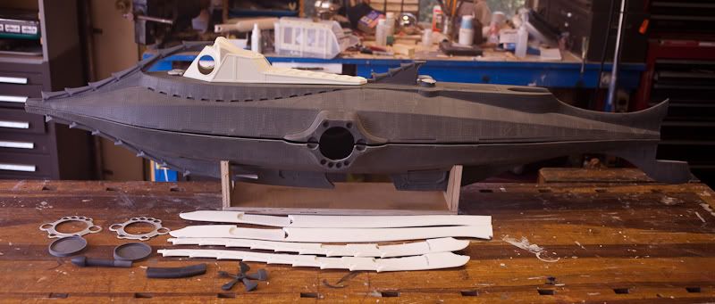
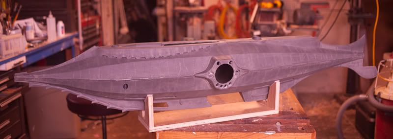
This thread wil chronicle my build of Custom Replicas 1/32 scale Nautilus from Disney's 20,000 Leagues Under the Sea. This kit is from the first generation run of parts and is about ten years old. Considering that CR recently anounced that they have discontinued production of this kit I feel very fortunate to have been able to pick this one up. When finished, the model measures 66 inches long and makes a spectacular display piece.

the model is going to be displayed in my Nautilus Home Theater which you can see here:
http://www.goldbergarts.com/nautilusscreeningroom/

The Nautilus model seen in the pictures on my site was borrowed for the photoshoot.

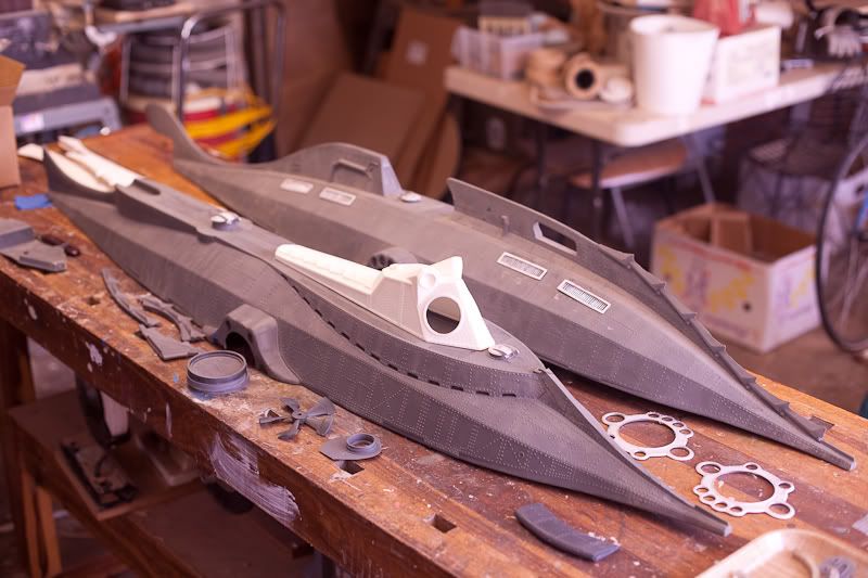
Here are the parts;
IMG_3512.jpg


IMG_3514.jpg


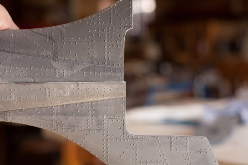
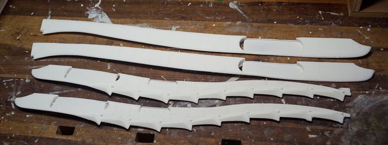
Overall, the castings are pretty clean. A bit of clean up required at the mold seams but nothing too bad. The hulls are warped just a tiny bit but should come together no problem. Some of the larger parts like the side fins and rackers are also warped, but again, I should be able to soften them in a hot box and straighten them out.
 
Aligning the Hull Sections

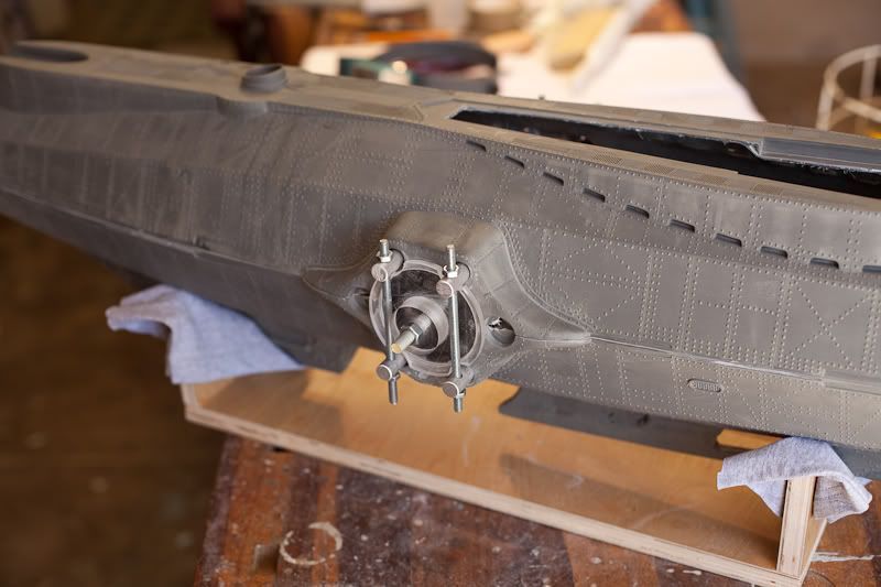
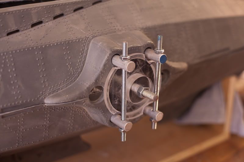
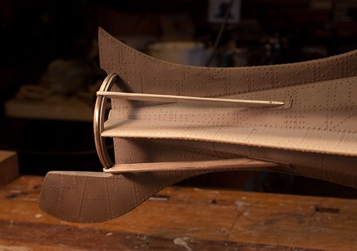
I've pretty much got the hull halves trimmed so they fit together as best as can be expected. There's a lot of alignment issues but nothing that can't be dealt with. The upper hull is about 1/8" shorter from the salon windows aft than the bottom hull, so it seemed to make sense to align the halves from the middle out. To do this reliably I tuned some stepped alignment plugs out of acrylic on the lathe that fit the circular salon window openings. These are held in place with a threaded rod that runs through from side to side. Rather than constantly be dealing with external strap clamps I ran four 1/2" aluminum clamping bars through the lighting holes, all held together with threaded rod and nuts. The whole assembly aligns and clamps the hull halves in the middle. Once the hulls are bonded together permanently, these can be discarded.

IMG_3516.jpg


IMG_3524.jpg


IMG_3524.jpg


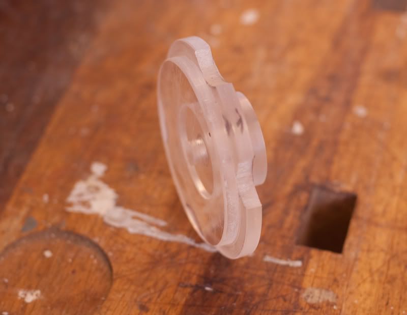
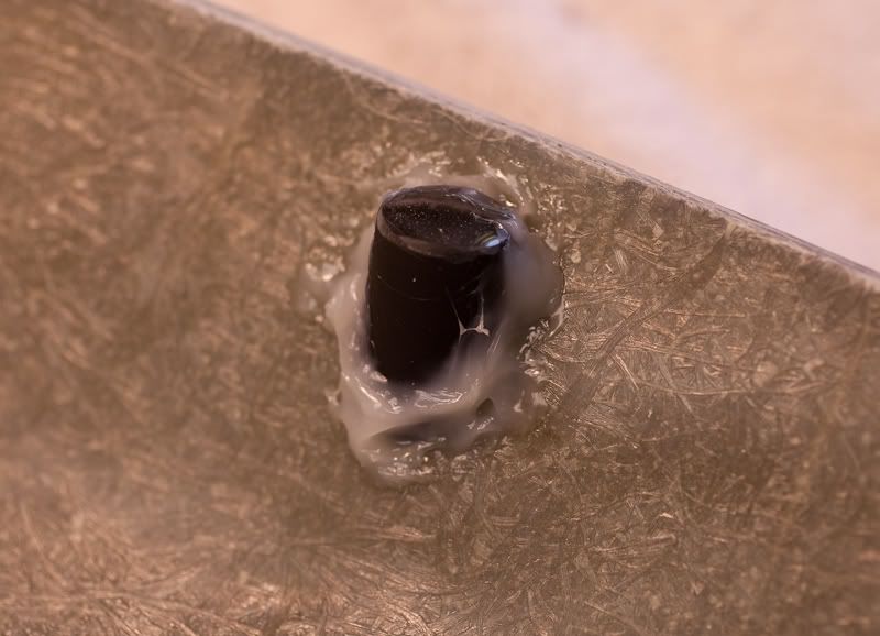
Here's one of the turned acrylic alignment plugs, notched out for the clamping bars.

IMG_3532.jpg


Here you can see how much the upper hull is shorter than the lower at the stern. Nothing that can't be flushed up with a some sheet styrene. The prow is pretty much even.

IMG_3537.jpg
 
Man, this is going to be great to watch. I would love one of these kits. Too bad it is now OOP. How much did it cost when it was being produced?
 
I think when these kits first came out they were around $1,200. The most recent versions were selling for $1,650 but they had additional details and the entire upper deck and wheelhouse had been remastered.
 
Nice work, Dave. Looks like you might have the right touch with submarines! Think you could build something like this?
attachment.php


Marcus
 
Ummm, I did, that's my work!

I'm just messing around a bit with you. I was there, managing the DQ camera department for Hoyt. I can't count the hours I spent tinkering and tuning (and cussing) the little process projectors inside those subs...

Anyway, this Nautilus will be a fine addition to your awesome screening room. I've got plans for a 4-footer and do hope to start a scratch-build of her sooner than later. Looking forward to your progress.

Marcus David Kraus
Dream Quest Images Camera Department Supervisor, 1988 - 1994

Marcus, I thought that might be you!

Dave G. - Dream Quest Model Shop Supervisor, 1988 - 1996
 
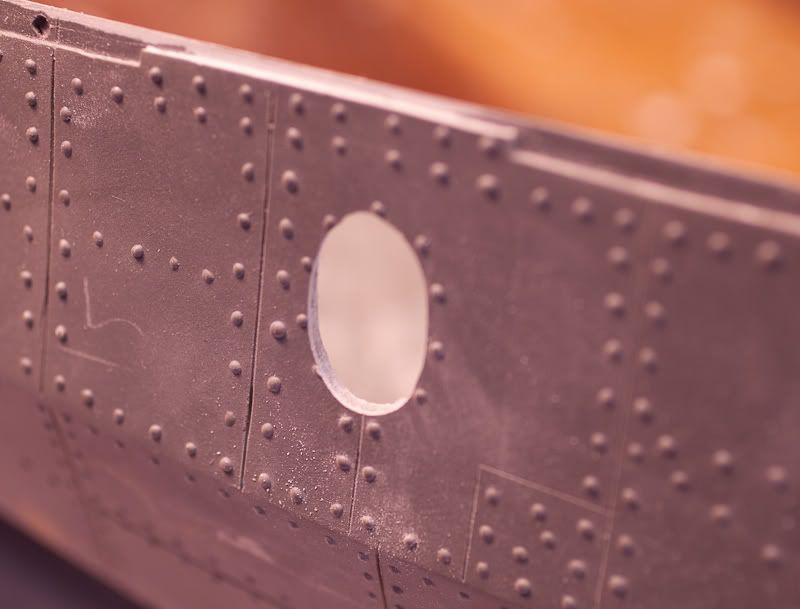
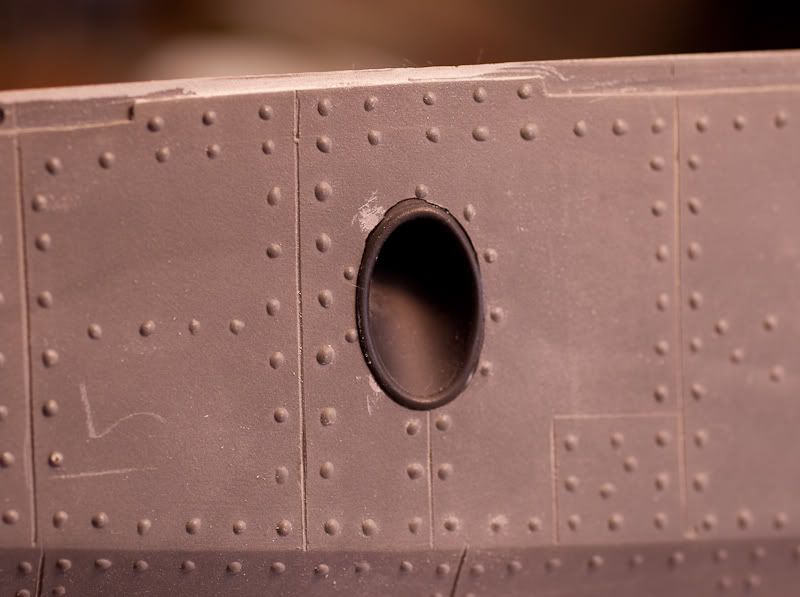
Okay, back to the build. There are several details on the lower hull which are only molded into the starboard side and must be added by the modelbuilder if desired. I guess this is to replicate the hero which was only detailed to be shot from the starboard side.

Installation of the anchor cup on the port side required grinding out an oval hole to fit the supplied part. There are an oval ring of rivets where the cup goes, offset from the cast in anchor cup on the starboard side. After fine tuning the opening to fit, the port anchor cup was glued in place with Plastic Welder.

IMG_3538.jpg


IMG_3542.jpg


IMG_3544.jpg
 
Joining the Hulls

I tried to figure out if there were any good reasons not to glue the hull halves together at this time. Couldn't think of any. The instructions call for installing all the little exterior detail parts to both halves first, then glueing them together. Considering how much manhandling the hulls will go through during the joining process, this seemed like a good way to wind up with a bunch of broken off parts! So the hulls will get joined first, then I'll install the parts.

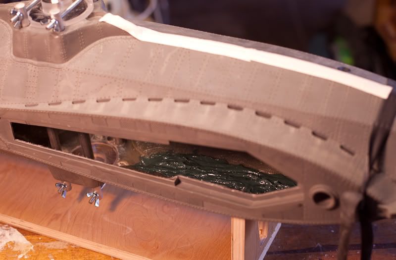
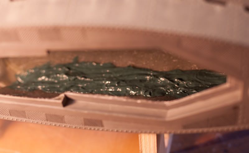
To join the hulls I'm working on one section at a time. First squeezing a small section of the joint together in alignment and securing it in place with super glue. I don't trust super glue for long term bonding strength, so the joint are then getting reinforced from the inside with Bondo-Glass. This product has fiberglass strands premixed into the auto body filler. It's much stronger and more dimensionally stable than plain ol' Bondo. It is also much thicker and doesn't 'flow' with gravity. This makes it much easier to butter along the inside of the joint. It stays put.

I've buttered the joints on each side, forward of the salon windows. The Bondo-Glass will be allowed to cure overnight before I start flexing and squeezing the aft joints together. Because of the limited access through the opening in the wheelhouse floor I was only able to reach about 12 inches of the joint. I'll do the rest up to the prow with regular Bondo, which will flow into where it is needed, after the Bondo-Glass has cured.

IMG_3556.jpg


IMG_3554.jpg
 
Side Keels and Rakers

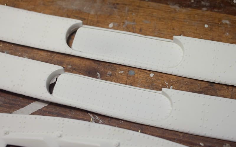
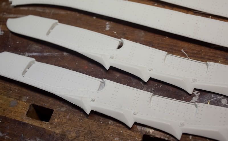
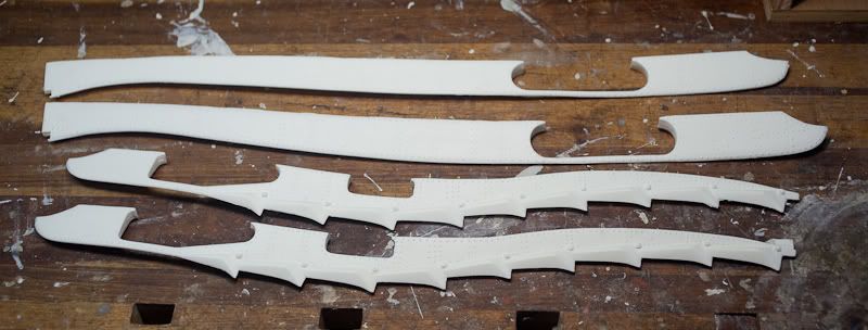
The side keels and rakers have the dive planes molded in place but I think they will look better if they are separate parts. They were pretty easy to cut out with a sharp scalpel.

IMG_3601.jpg


IMG_3602.jpg


IMG_3603.jpg


After the dive planes have been cut out.
IMG_3604.jpg
 
Wheelhouse Interior

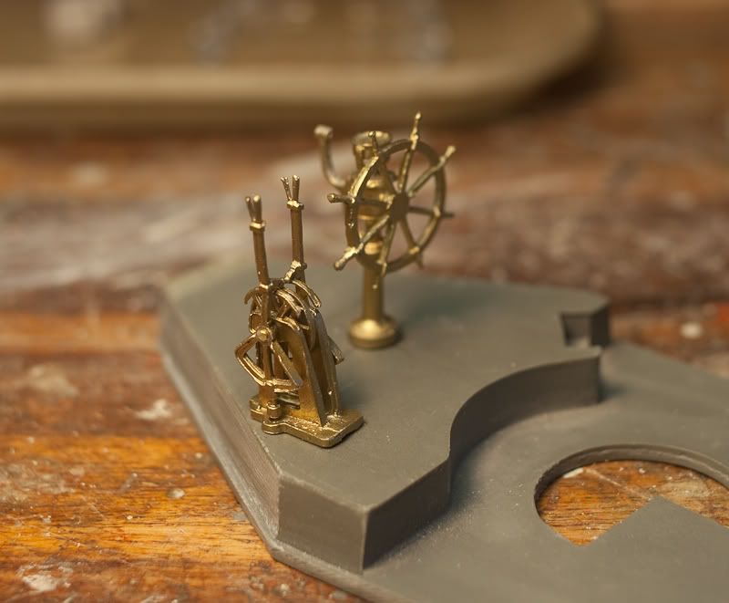
While some epoxy rivets are setting on the hull I've started on the Wheelhouse Interior. The white metal castings were a bit rough but they clean up okay. And the interior will only be visible through the domed ports.

IMG_3617.jpg
 
Ingenious method for securing the hull halves.

I visited Jim's shop recently, and he's still got bits and pieces of this kit cluttering up the joint. :)

Really looking forward to watching this one come together. She'll make a terrific addition to your home theater.

Thanks for sharing.
 
Filling Gaps in the Hull

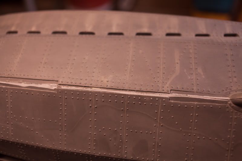
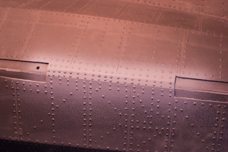
Since I elected to cut the dive planes free of the side keels that left gaps in the hull where the root of the planes use to seat.

IMG_3607.jpg


These were filled in with glazing putty and droplets of J-B Weld epoxy used to add rivets.

CRW_2566.jpg
 
Side Keels Attached

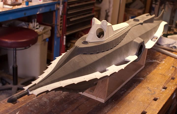
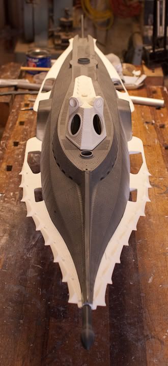
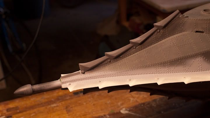
The side keels and rakers are now epoxied to the hull, and the bow spar is, ummm, proudly in place!

CRW_2590.jpg


CRW_2591.jpg
 
Awesome build up! I have always loved the design of the Nautilus. Your home theater is amazing as well!! :eek
 
Here the top front raker teeth have been installed along with the white metal prop guard.

CRW_2617.jpg


CRW_2610.jpg
 
Back
Top