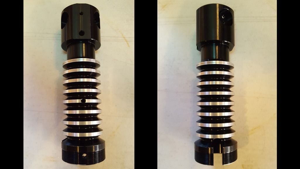
Ok so I got my two Graflex 2.0s today along with two TCSS 7/8" dia. LED/heat sink modules. As it turns out, both of the TCSS 7/8" dia. LED/heat sink modules are .881" in dia., not .880". Both are a very tight fit but can be forced into the blade holders. This would tend to indicate that the main bore of the blade holder is also .881" in diameter (down from .883"). I made a .880" and a .879" dia. ring from aluminum to test this. Both fit via in the blade holders via gravity but the .880" dia. one can get stuck here and there.
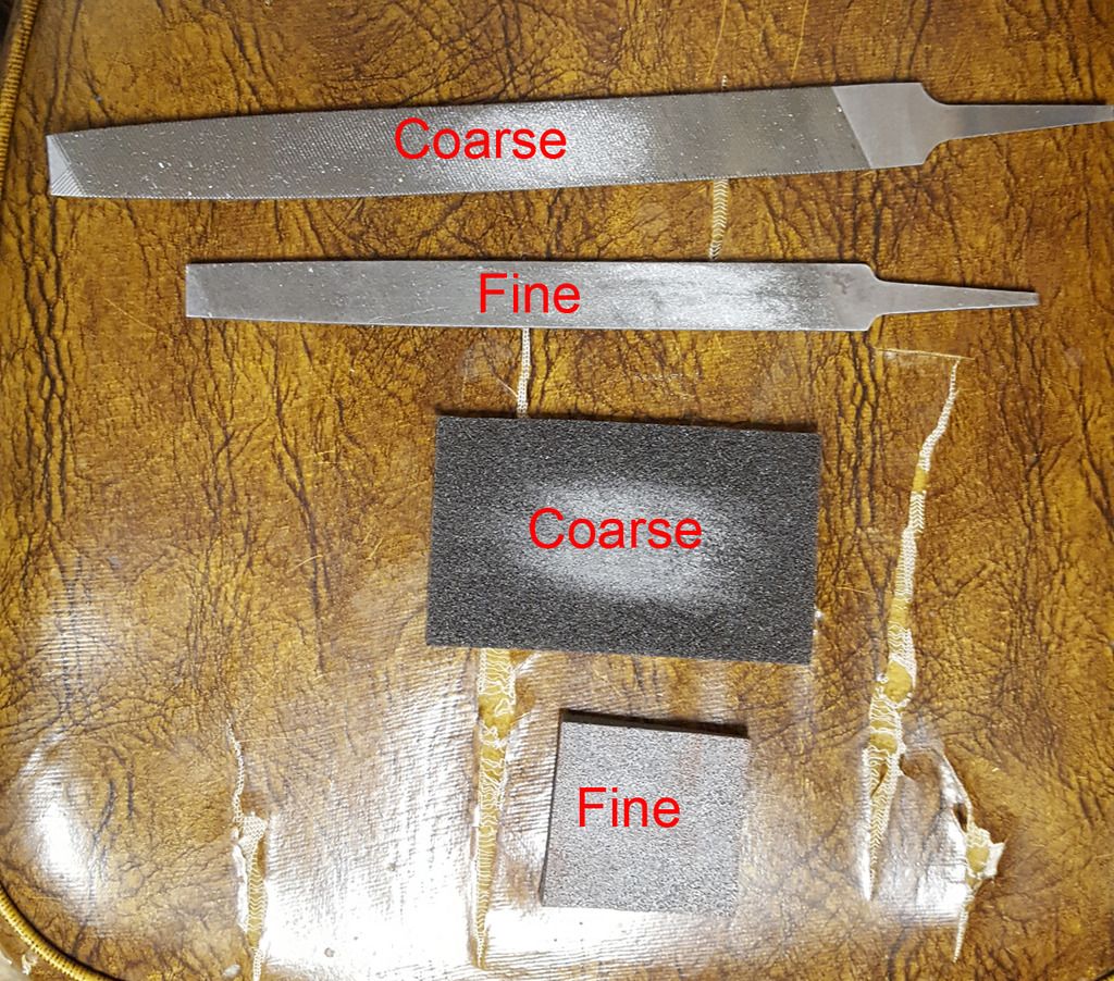
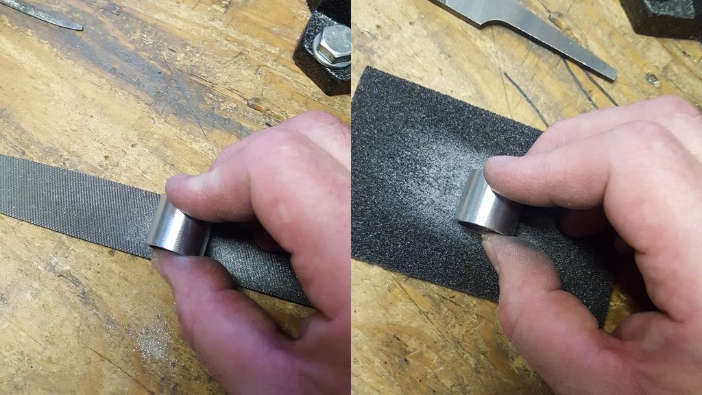
There are ways to get the TCSS LED/heat sink module to fit properly. One way to do this is to do what I did today. That being to use files and foam backed sandpaper. With about 5 to 10 minutes of filing and sanding, you can get the LED/heat sink module down to .879" in dia. which fits nicely. I did this using two files (one coarse and one fine) and two different grades of foam-backed sandpaper (one coarse and one fine). Instead of holding the files and sandpaper in my hand when working on the LED/heat sink module, instead I lay the files and sandpaper on a flat surface and hold the LED/heat sink module in my hand and rub it against the files and sandpaper while slowly rotating the LED/heat sink module.
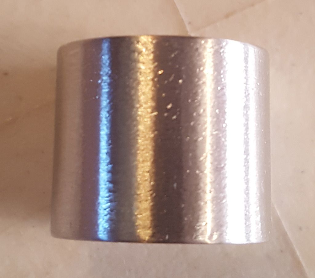
It looks a little rough when done but I'm guessing that this will not be of a concern to most.
I could have used my lathe, belt sander or grinder to get this done faster but I wanted to show that it can be done with just files, sandpaper and a little bit of elbow grease.
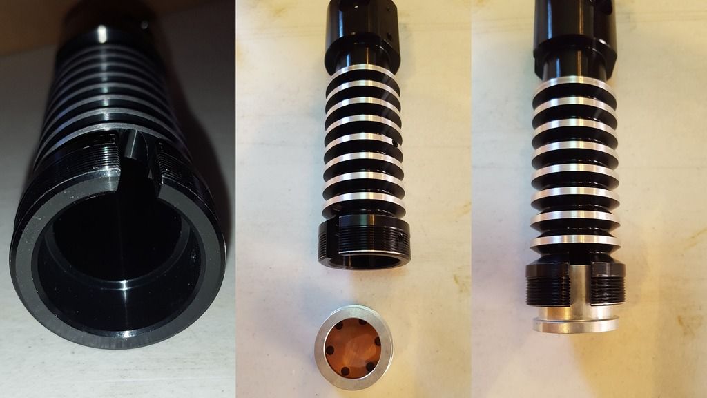
The bottom 1/2" of the blade holder is bored out to a dia. of about 1.026" to accommodate a TCSS MHSv2 LED/heat sink module.
It would also appear that the threaded ends of the 4 brass pins have been cut shorter so that they no longer protrude into the blade socket.
I guess that there are a few other changes as well that affect the installation of the G.O.T.H. 3Designs 3D printed chassis for the Graflex 2.0 but since I have never had an earlier version of a Graflex 2.0 in my hands, all I have to go on is what someone else posted over at another forum. Please note that the following was NOT posted by the designer of said 3D printed chassis...
"The changes have been detrimental to the padawan chassis more than the knight chassis...however, they are still somewhat fixable and useable...so if you have a knight or padawan chassis, don't fret! there maybe a solution...
***For the padawan...if you bought a padawan, it should have come with a separate 3D printed template to mark holes for drilling on to the grenade section...I believe that if you now use that template and bolt it to the grenade section, it will give you the wider surface you need to now bolt the padawan chassis to it! but of course there may be side wall clearance issues but that may be fixed with a little dremmeling!
***As for the knight chassis, you can always place the retention bolt higher (closer to the top) than it was intended...so that you can take advantage of the wider internal diameter of the grenade section located around 12mm from the base of the grenade section...or you can measure out a piece of polycarbonate tube to fill in that 12mm recessed wall at the base and now you should have the original space needed to bolt the knight chassis to in its original recommended location."
I hope that helps.
")
