mung
Sr Member
While waiting for the weather to improve to complete the painting of the Toy bash Truck project...
http://www.therpf.com/showthread.php?t=239673,
...I started another project.
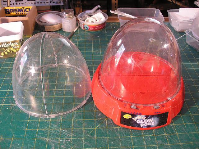
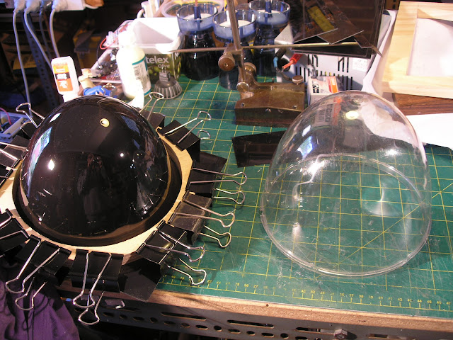
This was inspired by a charity shop toy find namely 2 Crayola colour explosion toys.
They consist of a motorised base that a clear plastic dome sits on top turned by a gear ring.
You are supposed to draw on the dome and an interior clear flat board with UV glow markers.
There is a series of purple UV Leds in the base that shine up through the edge of the dome and the board and
make the marker scribblings glow, all very psychedelic but very poorly reviewed, apparently kids get bored of it pretty quick.
I saw great possibilities in the largish domes however and picked them up for $3.00 each.
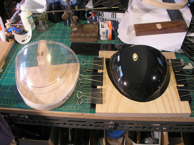
Here you can see I have already cut one of the domes in half with a razor saw following a line marked out with masking tape.
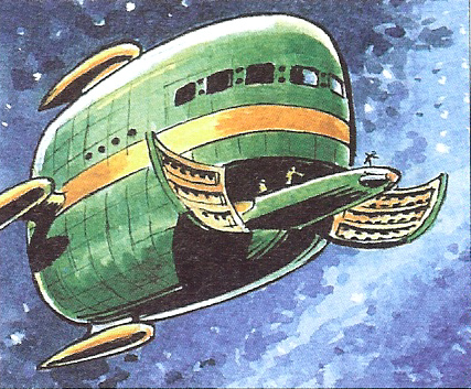
The half dome shape brought to mind a spaceship from the Dan Dare comic, the Bulk carrier.
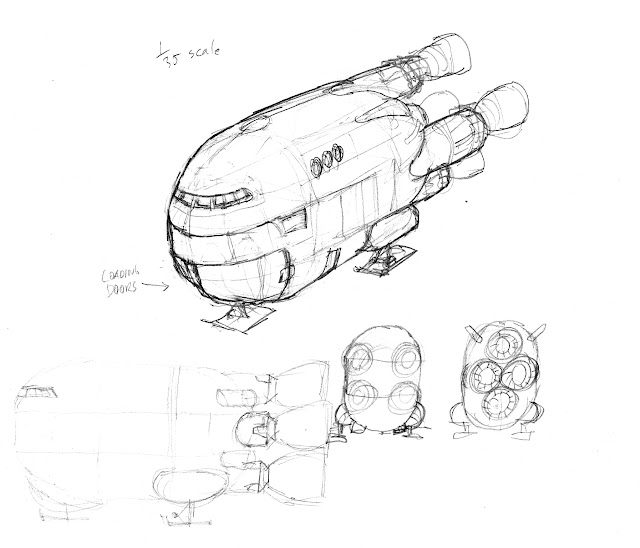
First of all I drew up a rough thumbnail in my sketchbook for what I had in mind, with a couple of alternative engine layouts.
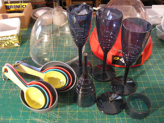
Along with the Crayola domes I dug through my crate of plastic shapes and pulled out a set of 4 acrylic wineglasses
( picked up a year ago on special at Target for $4.00) and two sets of measuring spoons ( also purchased more than
a year ago from Spotlight or as I like to call it Spot****e) made from polystyrene.
The spoons come in a set of 4 different sizes.
You nearly always need multiples of the same shape for sci fi models so I always buy at least 2 of a single item.
When I am out shopping I am always looking out for interesting shapes made from the right sort of plastic, namely
Acrylic, Styrene or ABS.
Cool shapes are getting harder to find these days as more stuff which used to be styrene or ABS is now made from polyethylene
and polypropylene which in my view are useless ( unless used as a master for a mold to make out of resin of some kind)
to the model maker as they can't be reliably glued, sanded, scribed, fillered or painted.
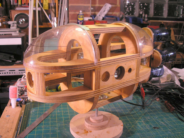
I made up a frame from 19mm plywood, somewhat overkill in thickness but I had a piece lying around.
I used the half dome to trace around for the shape of the horizontal frames, removing the thickness of the plastic.
The vertical frame shapes were drawn up in CAD using Draft Sight and printed out full size and using UHU stick glue
affixed to the plywood for cutting out on the band saw and jigsaw for the interior holes.
I used 3/8 inch thread furniture leg mounts as mounting points for the model.
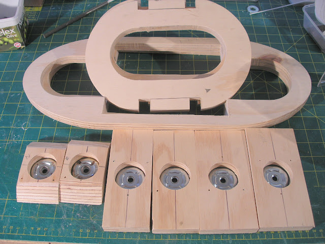
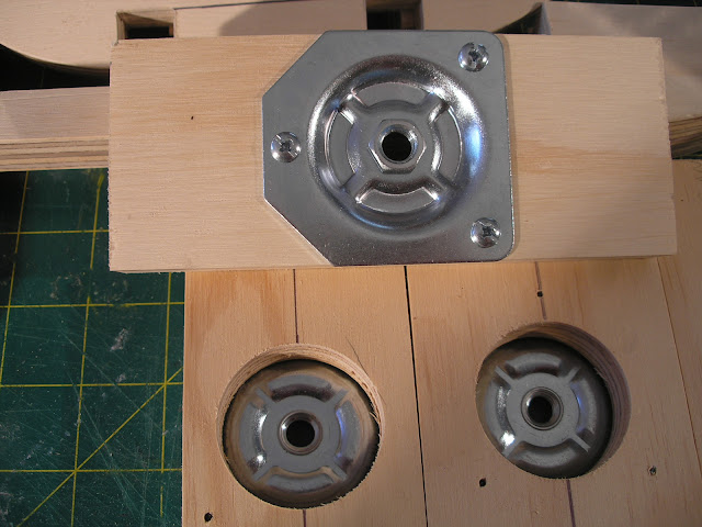
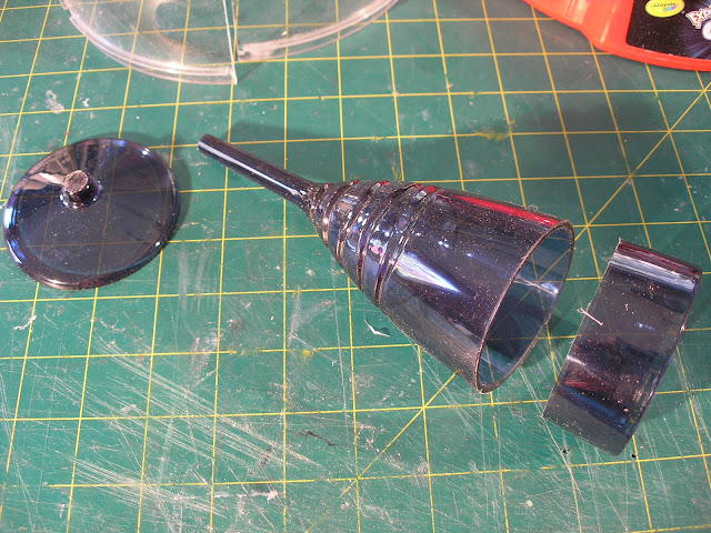
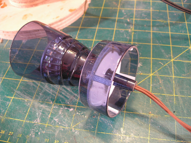
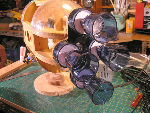
The wine glasses had their bases cut off and very carefully shortened by parting off in the mini lathe.
The cut off rings gets employed as the engine bell mounts with a disk of 2mm styrene glued inside.
Short lengths of Evergreen strip are glued in side to re-inforce the disks to stop them being pushed inward.
The stem of the glasses was also carefully drilled out in the lathe to allow the passing of the wire from some 2 pin
down light connectors which I then stuck inside with some black silicon.
I used a led bi-pin lamp to hold the ceramic connectors in position until the silicon set overnight.
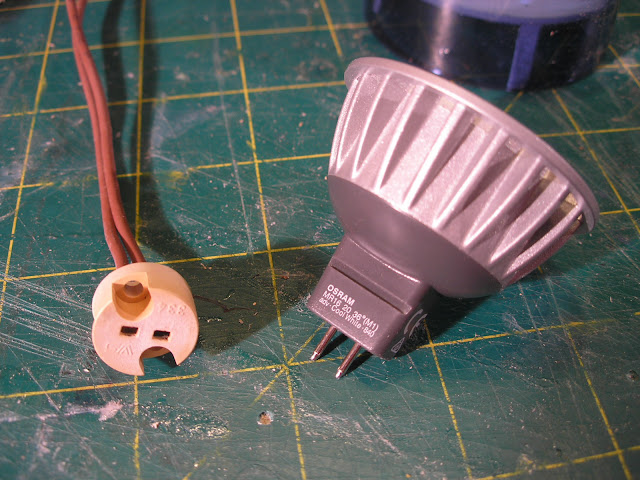
These LED down lights are not cheap but they use very little power and most importantly do not reach the plastic
melting temperatures that Halogen down lights achieve in seconds.
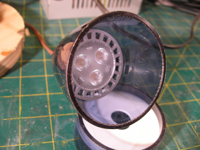
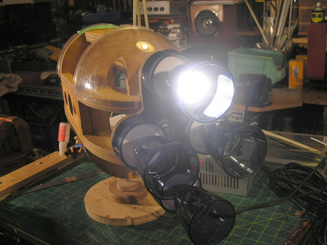
The lamp you see above was a spare I had from my bicycle light that I built.
I purchased a 4 pack of the cheapest ones I could find for $25.00 and they are of a different internal configuration.
Instead of the three distinct LED cells you can see in the test lamp above these have an arrangement of many surface
mount LEDs inside which actually makes for a more even engine glow.
See new lamp below.

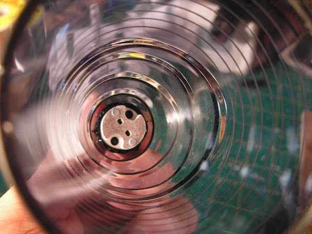
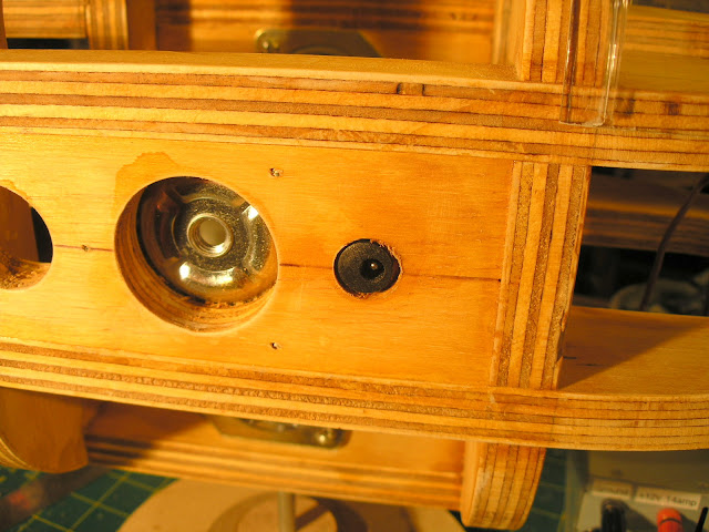
Here is the ceramic bi-pin connector siliconed into position inside the engine bell.
There is a spacer made from a ring of evergreen tubing behind the ceramic connector buried in the silicone adhesive.
It raises the connector from the bottom of the glass so that it sits at the correct height to mate with the lamp pins.
A long 3/8 " cup head bolt and a couple of scrap round bits of wood are assembled to make a work stand to support
the model during construction.
The frames were glued together and the domes and the acrylic wineglass engine bells were tried out in position.
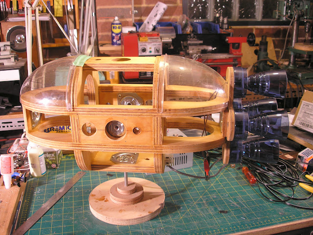
Below you can see the original test lamp in position and then switched on. Works a treat.
To get juice to the lighting I am installing some 2.5mm DC power connectors at the mount positions.
Originally I set up 6 mount points however I am debating whether to abandon the front and rear mounts altogether
as there is no convenient place to put the power connectors.
I have to confess I have a very strange quirk, which is always attempting to construct my models with features
conducive to filming.
I guess its a habit left over from the very short, long since past period as a VFX model maker.
When I was much younger I had many ideas for short films and built many models for them but found in the end
I never made the films, I just built the models
The chances of any the models actually getting filmed is pretty slim... but still I persist.
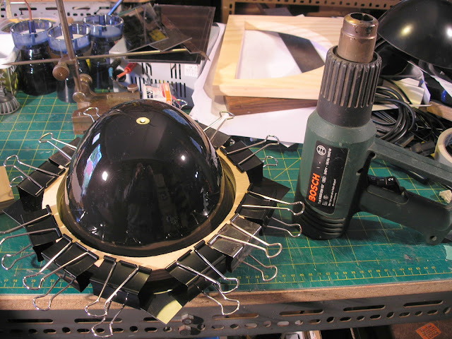
One of the complexities of using compound curved objects is that flat plate panel details don't conform to the surface
very well.
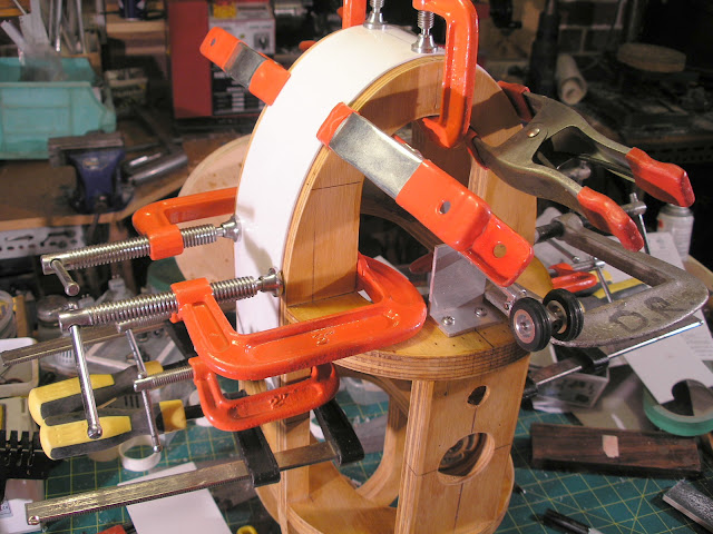
For this reason I pressed some heated 1mm styrene held in a wooden frame, over the shapes to later cut up into panels.
At first I tried a round frame pressing it over the full dome but it was quite difficult to get the plastic to stretch that far so I
made a side ways frame and pressed it over the half dome.
This is a large area for my heat gum to effectively heat evenly and is about as large as is possible to attempt.
A proper vac former would be ideal and I am going to have to build one... one day.
When vac forming parts for sci fi models it is pretty common to pull a skin for the hull shape and then after cutting
the shape free from the surrounding plastic returning it to the buck and pulling another thinner sheet over that just for
the panel detailing.
Everything then fits together nicely.
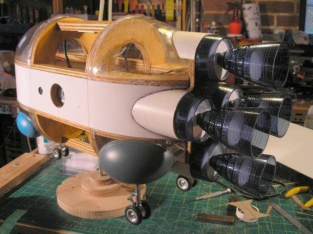
To add a bit more interest to the engine bells I decided to scribe some lines around the ends.
I screwed an OLFA plastic cutter blade to some scrap plywood and rotated the bells against it.
Then raised up the blade on some scrap plywood packers and scribed the next line and so on.
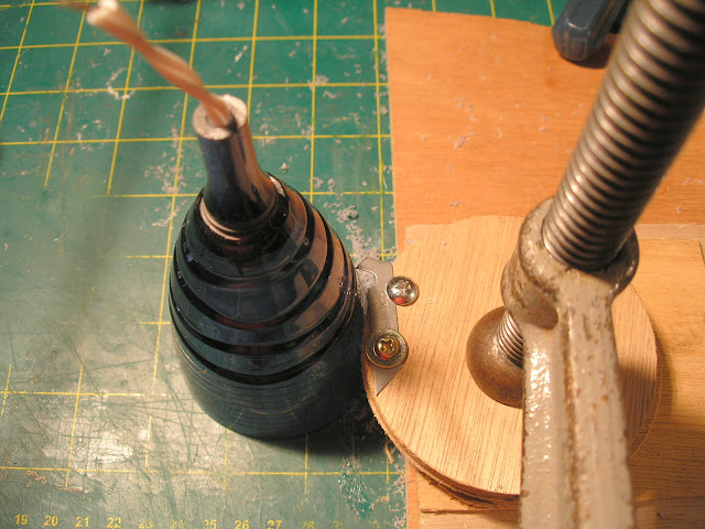
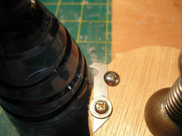
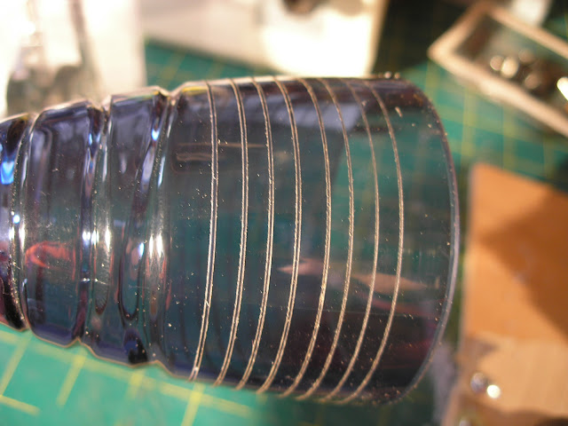
Not particularly even spacing I'll admit, I should have used more accurate spacing material, but its there now and
better than nothing.
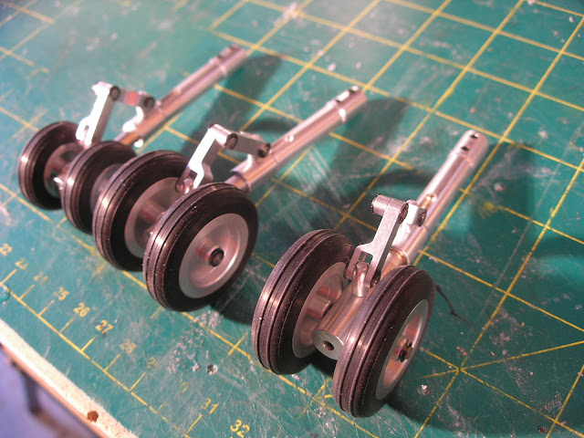
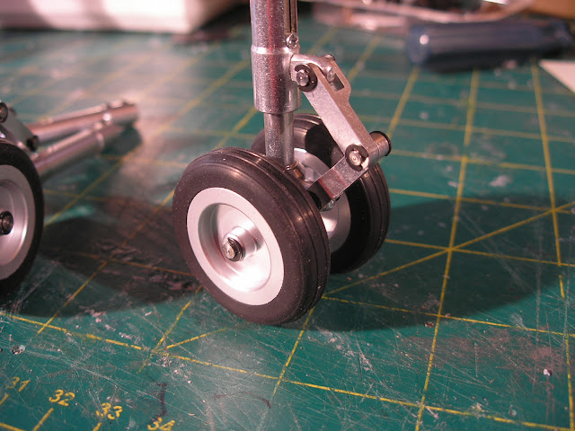
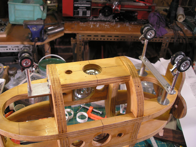
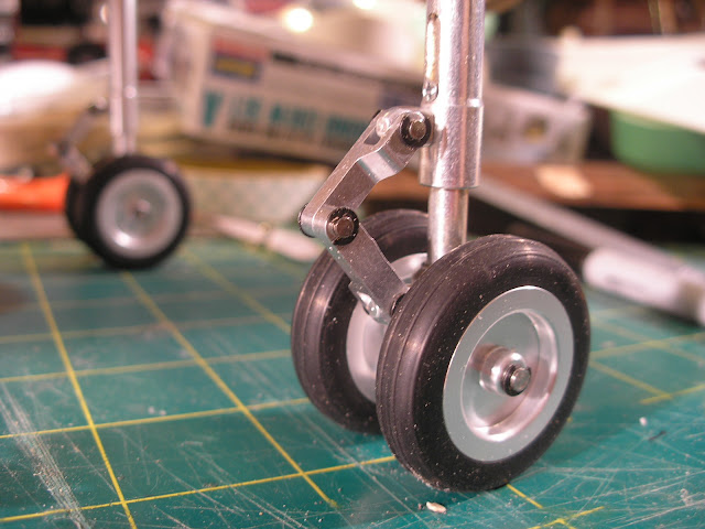
As this is a Lander it needs some landing pads of some sort.
I found these cool little sprung Oleo struts from HobbyKing. They were only $20.00. I couldn't make 'em myself for that.
Anyway the wheels will be removed and replaced with some pads.
The struts are designed to clamp with two grub screws to a 3mm rod. I removed the grub screws and tapped the ends M4.
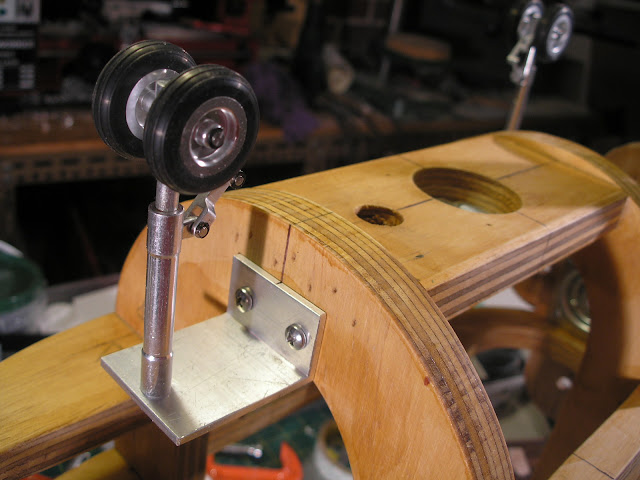
The front strut is the same size as the rears, just the wheels are smaller. It is mounted to a bit of aluminium angle screwed
to the front wooden bulkhead.
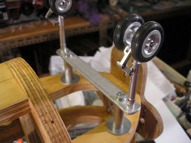
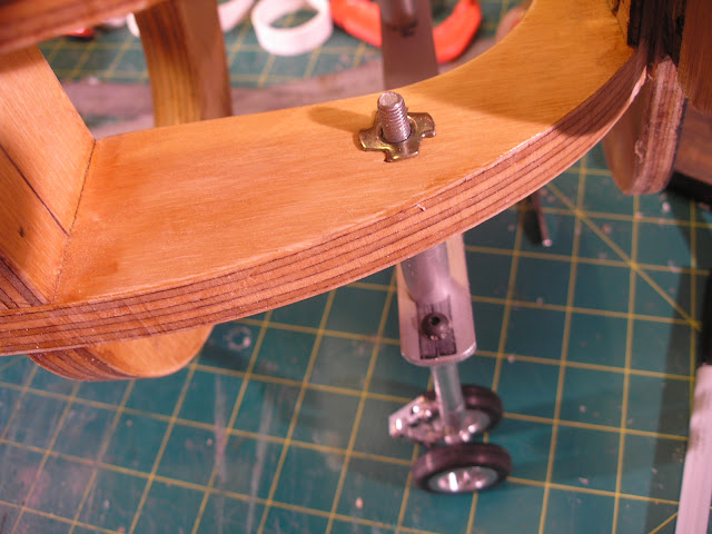
The rears are mounted to an aluminium strap bolted with two M6 bolts and aluminium tube spacers sitting on 1/4"
mudguard washers into M6 t-lock nuts embedded into the plywood frame.
The springs in the struts are pretty stiff and easily support the weight of the model so far with just a small amount
of compression.
Eagle eyed readers will note that I penciled in 1/35th scale on my thumbnail.
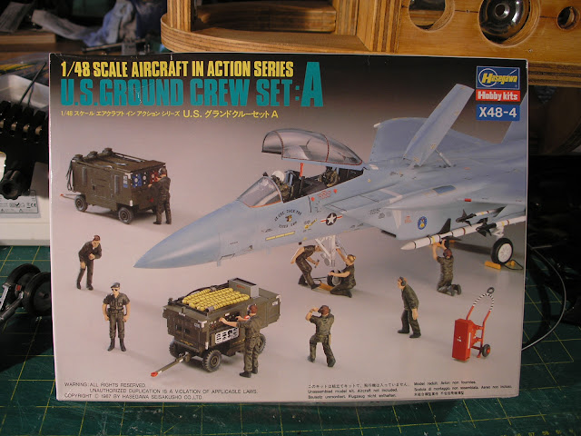
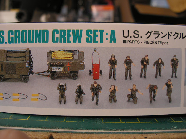
After holding up a 1/35 scale figure to the cockpit area I decided that 1/48th scale would be more suitable so got a
1/48 scale figure kit to eventually populate the cockpit.
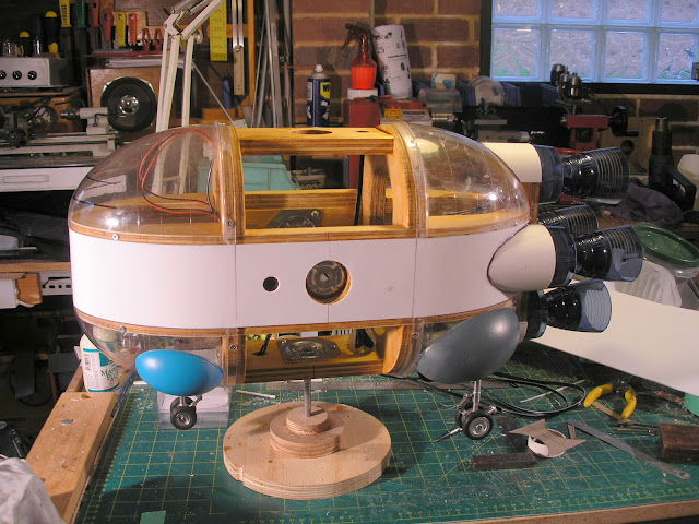
I wired up the engine lights and the power connectors an then started on skinning the frame with some 2mm styrene.
The roughened with coarse sandpaper styrene was superglued to the wooden structure.
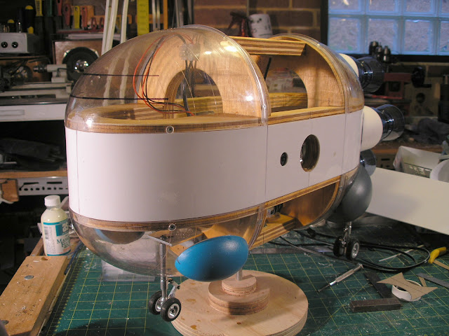
The top rear half dome was adhered in the same way.
The other half domes I have elected to screw on with small Phillips head wood screws to allow access to the interior
should any adjustment or repair need to be carried out at a later date.
Hopefully the Phillips heads should get lost in the rest of the surface detailing.
If not a small sticker painted the same as the rest of the hull, can be placed over each one which can then be removed
to provide access.
The engine mounts are fared in with some 75mm PVC storm pipe cut and sanded to fit.
Some 2mm styrene and some filler will be required here as well.
You can also see the measuring spoon blisters added as well.
It was quite difficult to figure out where to put the holes accurately for the rear landing struts.
I have found that accurate measurements still do not guarantee exact placement and some degree of "fitting" is
always required.
I started drilling a small hole where calculated it should go and then sighting through the hole to see how far out it is.
Then using a rat tail file gradually shifting the hole over in the direction it needs to go and finishing up with a tapered
reamer or a step drill to get it round again.
Some detail will eventually go around the area to disguise any errors if any remain.
The intention is to add lifting nozzles of some sort to the front and rear blisters to make good the Lander aspect of the design.
That's it so far,
more soon...
http://www.therpf.com/showthread.php?t=239673,
...I started another project.
This was inspired by a charity shop toy find namely 2 Crayola colour explosion toys.
They consist of a motorised base that a clear plastic dome sits on top turned by a gear ring.
You are supposed to draw on the dome and an interior clear flat board with UV glow markers.
There is a series of purple UV Leds in the base that shine up through the edge of the dome and the board and
make the marker scribblings glow, all very psychedelic but very poorly reviewed, apparently kids get bored of it pretty quick.
I saw great possibilities in the largish domes however and picked them up for $3.00 each.
Here you can see I have already cut one of the domes in half with a razor saw following a line marked out with masking tape.

The half dome shape brought to mind a spaceship from the Dan Dare comic, the Bulk carrier.

First of all I drew up a rough thumbnail in my sketchbook for what I had in mind, with a couple of alternative engine layouts.

Along with the Crayola domes I dug through my crate of plastic shapes and pulled out a set of 4 acrylic wineglasses
( picked up a year ago on special at Target for $4.00) and two sets of measuring spoons ( also purchased more than
a year ago from Spotlight or as I like to call it Spot****e) made from polystyrene.
The spoons come in a set of 4 different sizes.
You nearly always need multiples of the same shape for sci fi models so I always buy at least 2 of a single item.
When I am out shopping I am always looking out for interesting shapes made from the right sort of plastic, namely
Acrylic, Styrene or ABS.
Cool shapes are getting harder to find these days as more stuff which used to be styrene or ABS is now made from polyethylene
and polypropylene which in my view are useless ( unless used as a master for a mold to make out of resin of some kind)
to the model maker as they can't be reliably glued, sanded, scribed, fillered or painted.

I made up a frame from 19mm plywood, somewhat overkill in thickness but I had a piece lying around.
I used the half dome to trace around for the shape of the horizontal frames, removing the thickness of the plastic.
The vertical frame shapes were drawn up in CAD using Draft Sight and printed out full size and using UHU stick glue
affixed to the plywood for cutting out on the band saw and jigsaw for the interior holes.
I used 3/8 inch thread furniture leg mounts as mounting points for the model.


The wine glasses had their bases cut off and very carefully shortened by parting off in the mini lathe.
The cut off rings gets employed as the engine bell mounts with a disk of 2mm styrene glued inside.
Short lengths of Evergreen strip are glued in side to re-inforce the disks to stop them being pushed inward.
The stem of the glasses was also carefully drilled out in the lathe to allow the passing of the wire from some 2 pin
down light connectors which I then stuck inside with some black silicon.
I used a led bi-pin lamp to hold the ceramic connectors in position until the silicon set overnight.


These LED down lights are not cheap but they use very little power and most importantly do not reach the plastic
melting temperatures that Halogen down lights achieve in seconds.
The lamp you see above was a spare I had from my bicycle light that I built.
I purchased a 4 pack of the cheapest ones I could find for $25.00 and they are of a different internal configuration.
Instead of the three distinct LED cells you can see in the test lamp above these have an arrangement of many surface
mount LEDs inside which actually makes for a more even engine glow.
See new lamp below.

Here is the ceramic bi-pin connector siliconed into position inside the engine bell.
There is a spacer made from a ring of evergreen tubing behind the ceramic connector buried in the silicone adhesive.
It raises the connector from the bottom of the glass so that it sits at the correct height to mate with the lamp pins.

the model during construction.
The frames were glued together and the domes and the acrylic wineglass engine bells were tried out in position.


Below you can see the original test lamp in position and then switched on. Works a treat.


To get juice to the lighting I am installing some 2.5mm DC power connectors at the mount positions.
Originally I set up 6 mount points however I am debating whether to abandon the front and rear mounts altogether
as there is no convenient place to put the power connectors.
I have to confess I have a very strange quirk, which is always attempting to construct my models with features
conducive to filming.
I guess its a habit left over from the very short, long since past period as a VFX model maker.
When I was much younger I had many ideas for short films and built many models for them but found in the end
I never made the films, I just built the models
The chances of any the models actually getting filmed is pretty slim... but still I persist.

One of the complexities of using compound curved objects is that flat plate panel details don't conform to the surface
very well.
For this reason I pressed some heated 1mm styrene held in a wooden frame, over the shapes to later cut up into panels.
At first I tried a round frame pressing it over the full dome but it was quite difficult to get the plastic to stretch that far so I
made a side ways frame and pressed it over the half dome.
This is a large area for my heat gum to effectively heat evenly and is about as large as is possible to attempt.
A proper vac former would be ideal and I am going to have to build one... one day.
When vac forming parts for sci fi models it is pretty common to pull a skin for the hull shape and then after cutting
the shape free from the surrounding plastic returning it to the buck and pulling another thinner sheet over that just for
the panel detailing.
Everything then fits together nicely.


To add a bit more interest to the engine bells I decided to scribe some lines around the ends.
I screwed an OLFA plastic cutter blade to some scrap plywood and rotated the bells against it.
Then raised up the blade on some scrap plywood packers and scribed the next line and so on.


Not particularly even spacing I'll admit, I should have used more accurate spacing material, but its there now and
better than nothing.
As this is a Lander it needs some landing pads of some sort.
I found these cool little sprung Oleo struts from HobbyKing. They were only $20.00. I couldn't make 'em myself for that.
Anyway the wheels will be removed and replaced with some pads.
The struts are designed to clamp with two grub screws to a 3mm rod. I removed the grub screws and tapped the ends M4.
The front strut is the same size as the rears, just the wheels are smaller. It is mounted to a bit of aluminium angle screwed
to the front wooden bulkhead.
The rears are mounted to an aluminium strap bolted with two M6 bolts and aluminium tube spacers sitting on 1/4"
mudguard washers into M6 t-lock nuts embedded into the plywood frame.
The springs in the struts are pretty stiff and easily support the weight of the model so far with just a small amount
of compression.


Eagle eyed readers will note that I penciled in 1/35th scale on my thumbnail.
After holding up a 1/35 scale figure to the cockpit area I decided that 1/48th scale would be more suitable so got a
1/48 scale figure kit to eventually populate the cockpit.


I wired up the engine lights and the power connectors an then started on skinning the frame with some 2mm styrene.
The roughened with coarse sandpaper styrene was superglued to the wooden structure.
The top rear half dome was adhered in the same way.
The other half domes I have elected to screw on with small Phillips head wood screws to allow access to the interior
should any adjustment or repair need to be carried out at a later date.
Hopefully the Phillips heads should get lost in the rest of the surface detailing.
If not a small sticker painted the same as the rest of the hull, can be placed over each one which can then be removed
to provide access.

The engine mounts are fared in with some 75mm PVC storm pipe cut and sanded to fit.
Some 2mm styrene and some filler will be required here as well.
You can also see the measuring spoon blisters added as well.
It was quite difficult to figure out where to put the holes accurately for the rear landing struts.
I have found that accurate measurements still do not guarantee exact placement and some degree of "fitting" is
always required.
I started drilling a small hole where calculated it should go and then sighting through the hole to see how far out it is.
Then using a rat tail file gradually shifting the hole over in the direction it needs to go and finishing up with a tapered
reamer or a step drill to get it round again.
Some detail will eventually go around the area to disguise any errors if any remain.
The intention is to add lifting nozzles of some sort to the front and rear blisters to make good the Lander aspect of the design.


That's it so far,
more soon...
Last edited:
")
