Thank you John! I was inspired by your work.Lovely clean work Gus
I'm a fan of the fan
J
You are using an out of date browser. It may not display this or other websites correctly.
You should upgrade or use an alternative browser.
You should upgrade or use an alternative browser.
Deagostini Falcon. Anyone seen this?
- Thread starter Howard
- Start date

teslabe
Sr Member
Yes, thank you! It will be three piece construction or even four piece with photo-eched parts. I am working on possibility to include photo etched brass grilles with the kit now.
Please ignore the print quality of the fan. Is is going to be fixed shortly.
I have also adjusted the overall shape and changed the spacing of the grille. Here is the comparison photo showing it next to the actual filming miniature part:
Gus76, that looks great.......:thumbsup No idea what will come with the kit, but I'm sure it won't look as nice as your rendering.... I'm in if you decide to sell these.....
Will the fans have a center hole for mounting a motor shaft, size should start very small so the builder can enlarge it to fit the motor of their choosing,
just a thought. Again, very nice work.....
rustbucket
Active Member
Thank you. This is not a rendering though. Those parts are 3D Printed and primed.Gus76, that looks great.......:thumbsup No idea what will come with the kit, but I'm sure it won't look as nice as your rendering.... I'm in if you decide to sell these.....
Will the fans have a center hole for mounting a motor shaft, size should start very small so the builder can enlarge it to fit the motor of their choosing,
just a thought. Again, very nice work.....
Sent from my SM-T350 using Tapatalk
Thank you Darkview. This is a nice photo for a reference. However I would like to stay true to the 32 inch filming miniature as much as possible. For the fans though I won't be able to fit in this design because of the size restrictions.Nice work Gus76... Here's a close up picture of the 5fter fans..
http://i493.photobucket.com/albums/...5d25f90d7e05b037f36d341300950_zpshn8mqlea.jpg
Sent from my SM-T350 using Tapatalk
teslabe
Sr Member
Thank you. This is not a rendering though. Those parts are 3D Printed and primed.
Sent from my SM-T350 using Tapatalk
http://www.toybuilderlabs.com/products/fusion3-f400-production-grade-printer?variant=17655481796
Poor choice of words, sorry. What printer are you using? I have Rep2 and a Form 1+ clone that I got before CTC got a "cease and desist order" from Formlabs, don't use that printer much, too messy..... I do use the Makerbot a lot, but only in Hi-Res mode. It really helped with my Moebius B-9 build. I'm now looking at printers with a much larger build volume like the Fusion3 F400. Sorry for getting OT....
Hey guys, I'm new to the MF build so please bare with me if this has been covered. I've searched and haven't found anything on it yet. About the hold interior, If the floor was slightly bigger, say about 1/2" longer behind the couch/bunk area, and about 1/4" wider towards the Leia room, would it still fit in the model? Reason I ask is I've modeled up some floor tiles based on the actual size loading pallets and if I scale them down anywhere from 1/43 to 1/48 scales, it doesn't quite fit in the exact same space. I don't think it would pose a problem but without having a sense of how much room I have to work with, I don't know if I should proceed. The cut-away drawings I could find of the Falcon show the wall pretty much right under the dish base and from what I could see, the kit's doesn't go quite that far. But it's hard to see from the available pics.
I know there are floors out there already made, but I'd rather have the sense of pride knowing I did the design work as well. And if it's that much more accurate proportionally then all the better. Anyway, any info on this would be appreciated.
Bill
I know there are floors out there already made, but I'd rather have the sense of pride knowing I did the design work as well. And if it's that much more accurate proportionally then all the better. Anyway, any info on this would be appreciated.
Bill


Hey guys, I'm new to the MF build so please bare with me if this has been covered. I've searched and haven't found anything on it yet. About the hold interior, If the floor was slightly bigger, say about 1/2" longer behind the couch/bunk area, and about 1/4" wider towards the Leia room, would it still fit in the model? Reason I ask is I've modeled up some floor tiles based on the actual size loading pallets and if I scale them down anywhere from 1/43 to 1/48 scales, it doesn't quite fit in the exact same space. I don't think it would pose a problem but without having a sense of how much room I have to work with, I don't know if I should proceed. The cut-away drawings I could find of the Falcon show the wall pretty much right under the dish base and from what I could see, the kit's doesn't go quite that far. But it's hard to see from the available pics.
I know there are floors out there already made, but I'd rather have the sense of pride knowing I did the design work as well. And if it's that much more accurate proportionally then all the better. Anyway, any info on this would be appreciated.
Bill
So does that mean nobody is that far along to know if there is any extra room for a slightly larger hold area? Or is it just crickets chirping to my lack of knowledge?
So does that mean nobody is that far along to know if there is any extra room for a slightly larger hold area? Or is it just crickets chirping to my lack of knowledge?
We don't know 100% yet, as the hold hasn't been permenantly fitted to the hull yet.
There isn't much room for modification though, and if you did you'd need to wait for the upper hull frames to be completed as the hold fits to the curvature of the upper hull.
So does that mean nobody is that far along to know if there is any extra room for a slightly larger hold area? Or is it just crickets chirping to my lack of knowledge?
There are some guys expanding the main hold over on the model space website, but as jinnai said, no one knows for sure because the two halves haven't been sandwiched together yet. BTW it made my day when I saw that you quoted yourself. Awesome! :thumbsup
greedo737
Active Member
So, I assume we'll get the sidewalls that attach to the bottom frames. Then the top frames will attach to the sidewalls. How exactly will that work? How can we attach them if the top plates are already on? If we attach the frames to sidewalls first, how will we attach the top plates? Just something I thought of the other day while I was drinking and working on mine. Am I too stupid and missing something? Haha
There are some guys expanding the main hold over on the model space website, but as jinnai said, no one knows for sure because the two halves haven't been sandwiched together yet. BTW it made my day when I saw that you quoted yourself. Awesome! :thumbsup
Sorry, I guess that was a bit dorky and pushy.. I just was hoping to get an answer before I went through with having the floor printed. I did go ahead and have it made anyway. Just from looking at the sample model, I THINK I'll be ok. if not then I'll just figure something out.
Another thing about the hold floor. I know they probably changed up the stage during shooting for various scenes, but I noticed in some screen shots it looks as thought the grated area of the floor ends right behind the edge of the couch and then the floor drops down where there is some stored equipment. So is the floor in the middle raised higher than the edges or was that just for that one or so scenes?
Thanks again guys.
So, I assume we'll get the sidewalls that attach to the bottom frames. Then the top frames will attach to the sidewalls. How exactly will that work? How can we attach them if the top plates are already on? If we attach the frames to sidewalls first, how will we attach the top plates? Just something I thought of the other day while I was drinking and working on mine. Am I too stupid and missing something? Haha
The sidewalls screw directly onto the upper and lower hull frames. My assumption has always been that there'll be a plate with some detail molded on for the sidewalls, with raised greeblies covering the exposed screws.
We know this is already the case for the main power switch.
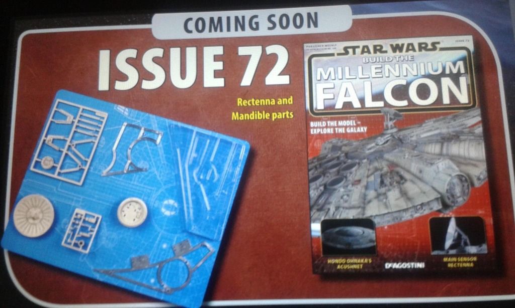
It'll still be speculation for at least another month or two. With issue 71 being the final removable panel for the upper hull, previous partwork experience tells me issue 72 will be greeblies for the engine deck.
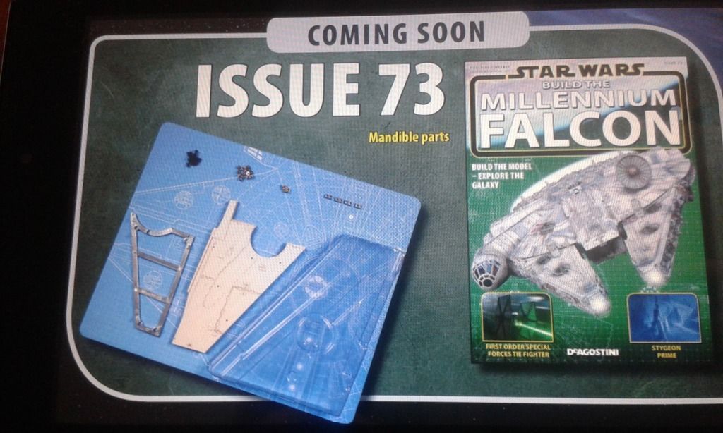
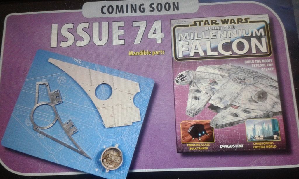
I speculate around issue 76 we will receive the start of the mandible frames, which directly screw to the bottom hull frame. From what I've attempted to figure out and understand, the mandibles will be fully built before the sidewalls, followed by the engine lighting and grill, then the sidewalls, landing gear, and finally decals and rectenna.
Of course I've been wrong before, but I have a strong feeling about this.
greedo737
Active Member
The sidewalls screw directly onto the upper and lower hull frames. My assumption has always been that there'll be a plate with some detail molded on for the sidewalls, with raised greeblies covering the exposed screws.
We know this is already the case for the main power switch.
It'll still be speculation for at least another month or two. With issue 71 being the final removable panel for the upper hull, previous partwork experience tells me issue 72 will be greeblies for the engine deck.
I speculate around issue 76 we will receive the start of the mandible frames, which directly screw to the bottom hull frame. From what I've attempted to figure out and understand, the mandibles will be fully built before the sidewalls, followed by the engine lighting and grill, then the sidewalls, landing gear, and finally decals and rectenna.
Of course I've been wrong before, but I have a strong feeling about this.
Thanks for the response!
")


Similar threads
- Replies
- 22
- Views
- 2,687
- Replies
- 5
- Views
- 1,154
- Replies
- 0
- Views
- 333