TRON Legacy - Identity Disc: Custom with Lights and Sounds

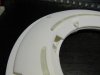
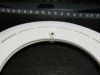
Went back to working on the Disc model a bit. I decided to add a narrow .5mm shadow reveal around the inner ring to help hide or minimize tolerance issues between the disc body and the inner ring. Its really hard to get the in lay perfectly flat.

Shadow line.PNG

Also been working on the electronic layout inside the ring. Starting at the top and going clockwise: MOD-1007 Sound Module, 1000uF Capacitor for NeoPixel Strip Power, AA Battery, Adafruit LSM303DLHC Compass+Accel, AA Battery, 4ohm 1Watt Speaker, AA Battery, Arduino Micro, AA battery, space for small proto-board, Haptic motor.

To improve the flow of light for the inner ring I pushed the NeoPixel strip outboard. Its going to be hard to get the light to wash into the inner ring. I'm unsure if there will be bad shadows 'til I get it all together. The alternative is more lights which I don't think the batteries can handle or only one side of the inner ring lights up.

Speaking of batteries, AAs are really tough to fit. I think they are going to block to much light so I'm going to try AAAs this week.


New Layout.PNG

Does someone know how should wire the (4) single battery holders to perform like my (4) Pack? Hold do I wire the (4) grounds and positives together?

AA Holder.PNG

Below is my breadboard diagram. Compliments of Fritzing Software.

Fritzing didn't have symbols for all my break-out boards so I had to improvise a little bit.

TRON PROTOTYPE_bb.png

-Z
 
Wiring batteries together in series (ie plus to minus) will increase the voltage (add voltage rating of each cell together for the total volts produced) but not the mA. Wiring them together in parallel increases the mA but not voltage (add the milliamp rating of each cell together to get the total mAh ;)

Looking good zook, keep it up :thumbsup
 
Couple new model snap shots. reorganized stuff to fit the buttons, Switched out for the AAA. Tested the electronics with the AAA and it'll run fine. I switched the compass to the top to create more space for the buttons.

New Layout_05.PNGTRON_DISC.PNG

I made the trapezoid element a button cover plate. I placed a center element to force it to click the left or right button but hopefully not both. One will be the main power, the other will active the blade.
Buttons.PNGButton Cover.PNG

I need to finalize some stand offs and then I can order the 3D prints this week. :)

-Z
 
Hi zook

If its not too late I have a couple suggestions regarding the lightpipe walls.

The first is a file tweak. I'd make some recesses for the LEDs at the base of each wall so the flexi strip sits flush when mounted (see sketch of red squares on left of pic)


The second is a post treatment after the parts are printed. Since the LED strips have to be mounted 90° to the optimum emitting angle, painting the underside, inner and outer walls of the lightpipes silver, then black will help to bounce the light upward and prevent any spillage reaching the blade making it look on when it's off.
 
Canobi,

I can't follow your thought. The LED strips are jacketed in a silicon tube. its roughly 4mmx12mm. Below is crude section of the layout.

I think it will be good not not make the top of the disc hold the LEDs so much. I think I'll cary the center track all the way up 10mm or so the LEDs can be glued with silcone adhesive to the bottom body of the disc with all the eltronics

Section.png
 
I've been working on the blade and inner ring. From the prop shot below you can kind of see the ring had half circle routing in it. This is design I've got for the ring & blade.

I've gotta re model the inner ring though, it is sitting a little low on the inside edge.

Blade Design.PNGbildschirmfotodisneyd23 (3).png

Also reworked the inside faces to be smoother and more simple.

Inside Edges.PNG

Few more things to finalize with the model before I send out for the prints. Clean up the stand-offs, Magnent Recesses and (4) Metal Inserts
 
3D Prints are for the disc shell are ordered.

I'm sending the blade and inner ring out for CNC quote through a co-workers shop. Prints won't arrive till Mid April not much to till they arrive then it will be filler primer & wet sanding time...

.DISC FINAL.PNG
Section.PNG
 
Last edited:
Been waiting in the 3D prints to arrive. Disc shell arrives on Friday 4/11. Blade and Inner Ring will be next week maybe. CNC was to expensive to ended up having them printed and I'll work on hand finishing.

Also got the 4 AAA single battery holders this week.
 
Disc Prints Arrived!

Faceting and build lines on the prints are almost non-existent. I think the sandy finish will look good for the portion of the disc with the rough sand-blasted finish. The rest I will primer and polish out.

The back shell (with Button cover) does have 3D print build defect though. It has 1mm step up 50% through the build that creates a warp in the disc. Should be able to work out a resolution with the printer though.

4mm x 2mm magnets will hold the shells together.

I also got some M3 countersunk aluminum washers for the front side inside cones. Backside cones will get magnets to attach to a back mounted disc holder I'm going to built also.

One lesson learned I would have oversized the mounting holes for washers and magnets 1mm to save sanding, and allow for a bit of paint.

Priming and finishing is the next set. Then I plan on building some silicone molds.


zook_one TRON Disc 01.JPGzook_one TRON Disc 02.JPGzook_one TRON Disc 03.JPGzook_one TRON Disc 04.JPGzook_one TRON Disc 05.JPGzook_one TRON Disc 06.JPGzook_one TRON Disc 07.JPGzook_one TRON Disc 08.JPG
 
Well it looks like you about got it licked. One thing I've noticed with LED strips (when they first came out) is that the LED's are spaced so far apart
leaving lighting "dead areas" and a lighting "bright spots". That hasn't changed much. They are however more convenient to use and power up with
a Micro-controller, making projects these days much simpler to build (along with 3d printers). Looking forward to seeing yours completed.

There are 144 per meter strips but powering those bad boys would be tough, you might run out of memory on the micro also and need to switch micro controllers. The photos I posted only have every third light lit. When I get the blade I'll post some shots fully lit so folks can see if they'd wanna shoot for more lights.
 
Whoa. I'd love to contribute some programming code to this. That way I can claim I helped (in some really small way...). Looks awesome dude!
 
The Blade and C-Ring arrived last week. Blade looks good. it'll be pretty hard to cast in clear resin though. We'll see how that goes.

Does anyone has any tips on casting a flat piece like this? I could use some insight.

Couple more lessons learned. I should of added some extra material at the blade where the 4 notches are around the perimeter, I didn't give myself enough tolerance. The prints are bit flexible one of the notches have a bit of light leak.

Some sort of extra groove in the blade to trap light leak from the edge lighting would probably have been a good idea as well.

Also there was shrinkage in the C-Ring when printed. It ended up 2 to 3 mm short. I'm going to try making it extra big by maybe a few more degrees so I can get a print that fits.

The prints are plenty stiff too. I tried to maintain 3mm min. I think you could go down to 2mm and have enough stiffness.

First pic is bit fuzzy but you can see the M3 countersunk washer dropped in. I'll have 3mm LED set in the hole as well. I don't have a means to trigger those lights yet though. Perhaps a double click button routine.

IMG_2767.JPGIMG_2768.JPGIMG_2770.JPG
 

Attachments

  • IMG_2771.JPG
    IMG_2771.JPG
    1.7 MB · Views: 129
  • IMG_2769.JPG
    IMG_2769.JPG
    1.7 MB · Views: 151
Worked on wiring up the disc today! Everything works but I don't have the light strips soldered in yet. I did have things a bit more tidy but had to pull things apart to trouble shoot. Helps if you wire thing to the right Arduino contacts. I was getting mixed up looking at is upside down etc...

More soon

IMG_1851[1].JPG
 
Video for the disc assembly prototyping. I'm going to head out and pick up the Primer, and some narrower gauge wire to rework some sections. Also need to rework the power jumper area to allow the capacitor to lay down.


Getting closer...
 
Last edited by a moderator:
Sweet! Just a thought, you might want to make the outer lights stay all on and just vary the brightness of them to create the spinning effect instead of turning them completely off if that makes sense. Looking forward to seeing the finished product!
 
Sweet! Just a thought, you might want to make the outer lights stay all on and just vary the brightness of them to create the spinning effect instead of turning them completely off if that makes sense. Looking forward to seeing the finished product!

ookid,

That's a great recommendation. I'll test that out once a get the disc painted an a translucent blade cast or cut.

-Z
 
This thread is more than 7 years old.

Your message may be considered spam for the following reasons:

  1. This thread hasn't been active in some time. A new post in this thread might not contribute constructively to this discussion after so long.
If you wish to reply despite these issues, check the box below before replying.
Be aware that malicious compliance may result in more severe penalties.
Back
Top