You are using an out of date browser. It may not display this or other websites correctly.
You should upgrade or use an alternative browser.
You should upgrade or use an alternative browser.
The Y-Wing "Green Leader" Project - NOW OPEN SOURCE!
- Thread starter DaveG
- Start date
MonsieurTox
Master Member
Given the prominent appearance of Y wings in "Rogue One" it will be interesting to see how close they are to the original trilogy models.
They wont be, from what Ive seen the engine cans and wing are centered, which is not correct. The pic is too small to see anything else though. I think it's going to be another different version of the Y, just like the Rogue One AT-ATs.
I'm sorry is that face palm directed at me?
No I was trying to face palm myself!
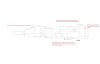
Here are a few area where I've noticed kit parts being cramped or changes needed in general. None are to scale yet, but it's a start.
I've noticed that Rhino has a free trial for 90 days, and I might be able to use that to make edits. Is this a good way to go? Does anyone have other suggestions?
I've noticed that Rhino has a free trial for 90 days, and I might be able to use that to make edits. Is this a good way to go? Does anyone have other suggestions?
Attachments
Hey Scott,
Thanks for the constructive notes! I have some yes, no and maybe comments.
Thanks for the notes on the bottom yolk. I missed that! Those are easy changes to make to the 3D file. I can do that and post a revised version if someone can give me some dimensions and/or good reference pix. The yolk on my "Green Leader" is already in place but I'm okay with the variations.
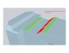
As to the area you marked "should be flush". The step was intentional based on my interpretation of the Alan Ladd model. If you look at the photo you can see how a portion of the rear section (red lines) is stepped down from the front section (blue lines). My intent was to then add a strip of styrene to bring a portion of this area up flush. I did this in several areas to make the 3D printed shells easier to fill and sand smooth. In the screen shot of my 3D model the green parts represent the added styrene plates. There are also several places on the bottom when I did this as well. when I get a chance I will post information on that as well to avoid confusion.


I'm a little confused by your note of the added shelf at the back. Here are shots of the back of the Ladd model and my 3D model. Again, the green represents added styrene strips to surround the tank deck. Am I missing something?


By all means download the 90 day trial of Rhino. It's a great program.
Thanks for the constructive notes! I have some yes, no and maybe comments.
Thanks for the notes on the bottom yolk. I missed that! Those are easy changes to make to the 3D file. I can do that and post a revised version if someone can give me some dimensions and/or good reference pix. The yolk on my "Green Leader" is already in place but I'm okay with the variations.
As to the area you marked "should be flush". The step was intentional based on my interpretation of the Alan Ladd model. If you look at the photo you can see how a portion of the rear section (red lines) is stepped down from the front section (blue lines). My intent was to then add a strip of styrene to bring a portion of this area up flush. I did this in several areas to make the 3D printed shells easier to fill and sand smooth. In the screen shot of my 3D model the green parts represent the added styrene plates. There are also several places on the bottom when I did this as well. when I get a chance I will post information on that as well to avoid confusion.
I'm a little confused by your note of the added shelf at the back. Here are shots of the back of the Ladd model and my 3D model. Again, the green represents added styrene strips to surround the tank deck. Am I missing something?
By all means download the 90 day trial of Rhino. It's a great program.
Last edited:
Hey Dave. Thanks for the feedback. I didn't do all my comparisons with the Ladd Y. I used a lot of comparisons of Steve Neisen's and Julien's models.
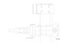
i've noticed the back end is longer on the EFX prototype. Pic attached. I see it's different than the Ladd Y. So I'm confused to. Maybe a difference between the actual Ys?
And on Julien's area where styrene is added towards the front of the fuselage, there are lines scribed in the styrene where the step is in the printed part. I think it'd be near impossible to scribe the printed part. Therefore my suggestion to get rid of the step. Pic attached.
Kit parts I have would suggest that the fuselage, and front cap for it, would be widened from the centerline a few millimeters. Right now, the airfix lunar module and hurricane oil pans have no space at all across the top. And the airfix nelson parts on top of the front cap need some extra width to fit. I'll try to get dimension suggestions soon, and pics to show what's happening.
No big deals except that I think the yoke and width of the fuselage could still be addressed. BUT also, widening the fuselage eats up wing space, and I can't determine that yet, until I have parts to compare.
Attachments
Last edited:
Hey Scott,
I intentionally did not use photos of other replicas like the Niesen/EFX, Tox, etc. as reference as I knew there were some interpretations that they had made that I would make differently. I also didn't want to be copying the hard work of someone else (digital "recasting"). I referred almost exclusively to the photos of the Ladd Y-Wing (Gold 2?) and photos of another original Y that's in private hands. I believe it was the one Steve used as reference for the the EFX version. I have no idea what's going on with the back end on the EFX Y. There's not a single photo of any original Y that looks like that, even the one in private hands.
As to the sloped area, yes, thank you for reminding me, the surface on the 3D printed part is lower to allow adding styrene to create the scribed surface. I was in the process of adding those to the 3D model when I got diverted onto the pattern making for the L'Eggs engine parts and forward fuselage. You "early adopters" are finding those places before I can get information out on it! :eek As I mentioned there are several of those places on the sides and bottom too.
I can tell you that in NO AREAS did I intend for the 3D printed shells to be scribed or cut away, other than maybe a drilled hole or two. All surface details are intended to be additive.
Last edited:
MonsieurTox
Master Member
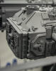
And on the painted efx, you can see how deep that end piece is from the side. All one piece this time, and not a tacked on piece. Probably a difference in Ys.
Ohhh that's ugly ! Bug mistake, your other pic doesnt show the eFX proto but a MR Y.
To clarify things :
-The surround was not styrene but part of the too and bottom half.
-The back plate is a separate casting with no surround that gets inserted into the hull
-All the screen used Ys were made this way, Only Red Jammer has a different configuration with a surround added to the back plate that have been glued in the body surround, and a bit lower, that creates a step.
If you're studiying the Y's, avoid Red Jammer as it' sa whole different bird than the other which were identical except a few added kitparts.
-The surround was not styrene but part of the too and bottom half.
.
Yes, yes, I understand that the surround was not styrene on the final models but part of the entire hull castings. However, I did not include the surround as part of the 3D printed fuselage for several reasons; A) it would have made the surfaces of the 3D printed part harder to fill and sand to get smooth, 2) depending on the orientation of the part in the printer and the type of printing material it could have been weak and prone to crack, iii) thin sections generally don't print cleanly unless done in SLA resin which is expensive and not good for archive parts.
MonsieurTox
Master Member
Yes, yes, I understand that the surround was not styrene on the final models but part of the entire hull castings. However, I did not include the surround as part of the 3D printed fuselage for several reasons; A) it would have made the surfaces of the 3D printed part harder to fill and sand to get smooth, 2) depending on the orientation of the part in the printer and the type of printing material it could have been weak and prone to crack, iii) thin sections generally don't print cleanly unless done in SLA resin which is expensive and not good for archive parts.
This was to explain how it made, it's up to you to design it the way you want !
I printed mine with the hull :
The upper half was printed in 3 parts vertically
The bottom half was printed as a single part horizontaly, no problem. I am not using PLA or ABS though.
The surround is about 2mm (a tad over) so it's pretty thick !
But yeah it cracked on one place on mine, which is not a big deal since it's going to be molded.
I reckon it's a bit more work to not print into several parts. Have just printed the neck in two halves (top/bottom) and the bottom one will need some patience to sand hehe
")
The cockpit is pretty thin on the rear ones (at least the front and back edges) but I think I'm going to print it too,I have printed the large armor panels of my AT-AT wich are 1 mm thick without problem
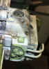
Here's the process of roto-casting the L'Eggs engine cones. a mold box was built out of 1/4" MDF with angled sides and an open bottom. It also had a 1 inch flange all the way around so that the same box used to pour the mold could be used to attach it to the roto-caster. the pattern was secured to a flat plate with a screw. Then the whole thing clamped together and the silicone rubber poured.


The mold box was bolted to the inner rotating frame of the roto-caster. The mold drops in and the resin poured. A thin sheet of non-stick plastic was laid over the top of the mold, then a square of MDF was clamped in place and the machine turned on to spin.


The machine spins for about 10 minutes while the resin congeals and stops sloshing around. At that point the resin is not hard enough to demold, so I have a second mold to run in rotation. Pop the first one out, drop in and run number two while the first one continues to cure, back and forth, back and forth.


The mold box was bolted to the inner rotating frame of the roto-caster. The mold drops in and the resin poured. A thin sheet of non-stick plastic was laid over the top of the mold, then a square of MDF was clamped in place and the machine turned on to spin.
The machine spins for about 10 minutes while the resin congeals and stops sloshing around. At that point the resin is not hard enough to demold, so I have a second mold to run in rotation. Pop the first one out, drop in and run number two while the first one continues to cure, back and forth, back and forth.
Last edited:
Hammer3246
Sr Member
Sweet
Sent from my SM-N915W8 using Tapatalk
Sent from my SM-N915W8 using Tapatalk
Thanks guys! I got a query about what resin I'm using, Silcast II from Sil Pak. I've added 17 percent of their Prolite FR-50 filler powder which thickens the resin and improves roto-casting performance. SilCast is normally white, I add a little bit of black pigment to turn it light grey. Makes it easier to inspect the parts for flaws.
Hammer3246
Sr Member
And on the painted efx, you can see how deep that end piece is from the side. All one piece this time, and not a tacked on piece. Probably a difference in Ys.
I was under the impression that the EFX was uber accurate, why such a glaring mistake?


Similar threads
- Replies
- 150
- Views
- 16,804
- Replies
- 2
- Views
- 483
- Replies
- 3
- Views
- 662
- Replies
- 12
- Views
- 1,302