Long slow ANH DL-44 build

rogerrabt

Active Member
Well, I've got a Denix and not much else. Will be a bit of a long wait for the next round or parts from DEC (yes, that's ok!). So I'll be making this really crappy looking Denix look as close to real as I can for a while. Today, I started on the rear sight. Wow this metal is SOFT. Shaping goes very quickly except the files clog up fast.

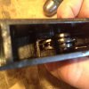
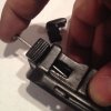
The original Denix sight - button on the wrong side.
IMG_2074.JPG

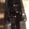
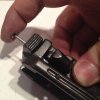
Rat Tail file to start shaping it correctly (I hope)
IMG_2075.JPG

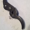
Getting close
IMG_2076.JPG

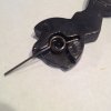
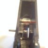
Button on the sight with a big step on it.
IMG_2077.JPG

File ridges deeper, file off the step from the mold, repeat.
IMG_2078.JPG

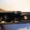
Re-assembled sight. Doesn't that 50 look weird? May have to think about that.
IMG_2079.JPG
 
Last edited:
Glad you were able to get in on this production run. I found his site a day after orders closed. I'm curious as to the finer points of his kit and assembly, so while i await the next production run(he said summer, hopefully), im going to creep on your build. I wish you the best! Now im off to do more research...or sleep....sleep is good.
 
Glad you were able to get in on this production run. I found his site a day after orders closed. I'm curious as to the finer points of his kit and assembly, so while i await the next production run(he said summer, hopefully), im going to creep on your build. I wish you the best! Now im off to do more research...or sleep....sleep is good.

I didn't get in on this run. Sure hope to get one this summer if he does another run then. That would be great. It will be a very very slow build.
 
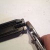
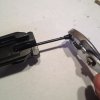
Today I practiced taking down the Denix Mauser and reassembling it. Probably not good to do this too many times since it's pot metal. Photos below may help someone but they're also here so I know how to put it back together when the time comes, right?

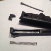
All the parts. Just about everything disassembled that can be.
0 All the parts.JPG

The most complicated part is how the trigger spring sits in there, so here are two photos before I removed it. One from the front and one from the rear. Plus one showing how the spring sits in the trigger if you're lucky enough that it didn't go flying out when you pulled the pin.
1 Trigger front.JPG1 Trigger back.JPG2b Trigger w Spring.JPG

The hammer spring pretty much can only go in one way. It even wedges itself in there so it's pretty easy to deal with.
3b hammer w spring.JPG

Disassembling the upper and bolt:
The pin is just a wedge. Rock it back and forth while pulling.
4a pin out.JPG4b pin out.JPG

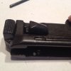
Push the bolt stop toward the front and the spring will cause it to rock up. Don't pry it out with a screwdriver.
4c bolt stop.JPG 4d parts.JPG

The tricky part about reassembling the bolt is the spring. I use a nail that I've filed the point off of for pushing all the pins out and also to push the spring forward while sliding the bolt stop into place. Then just tap the pin back into place and you're set.
4e push spring.JPG 4f push bolt stop.JPG

Reassembling the trigger
Do this before the hammer. Slide the pin in from one side so it's flush with the inside. You shouldn't need a hammer for this.
2a Trigger Assy.JPG

With the spring in the trigger (it will slide around), slide the trigger in facing forward and push the pin in so it just holds the trigger in place, flush with the inside. Then with your thumb on the pin, push down on the spring as shown with a small screwdriver and push the pin through the loop in the spring.
2c Trigger push.JPG

Last photo shows the trigger in place and how the trigger pawl sits on the catch for the hammer.
2d trigger in.JPG
 
Thank you James Kenobi!

I scalloped the end of the upper. I think it's pretty close, but the Denix had longer ramps down to the corner than they should be. Looks ok.

IMG_2118.JPG

So... I've been thinking. Has anyone ever remade the pin so it's not so ugly? I've seen people file them off, but that would make disassembly a pain. How about making one more like the real pin? Let's not go drilling holes in the end of the bolt or anything crazy like that. Just make it so the end cap looks like the screw top it's supposed to with a notch to insert and twist. There's actually almost a 1/4" gap between the end of the bolt and the bolt stop that could support a key on the pin.

Mockup with a ball point pen since the spring is pretty much perfect. (and a little photoshop). The flag represents a little key.
IMG_2124.JPG

The gray blob would be a keyhole going all the way through. The white blob is a shallow divot to hold the end of the key.
IMG_2126.JPGIMG_2125.JPG

Kinda like this assembled.
IMG_2123.JPG
 
Last edited:
Today I did more thinking about the pin, but no real progress on that.

Made it to the shop and did mill work!
Milled in the extractor. Just all with a 5/32 end mill.
2.JPG

Milled in the missing notches at the top of the upper. 3/16 mill for this.
1.JPG

Then spent a ton of time figuring out how to keep that rear sight from flopping around. Involved adding a compression spring that rides between the upper and bolt and presses the sight down. Details are on this other thread here.
 
Awesome work on the extractor and spring for the sight. Ive been trying to figure out a way to CNC the extractor but I think I may just have to go with a manual mill instead
 
Over the weekend, I made some progress.

Removed the logo. Worked on fitting the new grips. A little chisel work on the wood to remove the excess in the center. Sawed out the central grip support on the lower. Then milled each side 0.050" thinner so the grips sit properly and it doesn't feel so bulky. Still some shaping work to do here, but at least all the major work is done.
IMG_2149.JPG IMG_2148.JPG

Inspired by jason_ehl 's work on the magazine base plate, I worked on a similar project. That's some tough work. I'm still not quite done with lots of shaping left to do. I think it'll be nice when it's done. The screw holding it on in the photo above is temporary. A more permanent "button-like" solution is coming soon.

IMG_2150.JPG IMG_2151.JPG

I hope you all like the progress pics.
 
Last edited:
Fantastic work so far! The extractor looks great. I really wish i had access to a mill so that I could do mine the same way. That magazine baseplate mod looks intense.

I also was thinking about modifying the firing pin. The best solution I could think of (which I have not yet tried) was to tap the hole and thread the pin... or even replace the pin with a long threaded rod with all but the last 1/4" of threads ground down smooth.
 
Thanks!

I also was thinking about modifying the firing pin. The best solution I could think of (which I have not yet tried) was to tap the hole and thread the pin.

I like the way you're thinking. Maybe even threading it into the end of the bolt.

This is what I've been pondering. It's complex and involves drilling out the bolt stop. A bit scary.

pin.jpg
 
Thanks!


I like the way you're thinking. Maybe even threading it into the end of the bolt.

This is what I've been pondering. It's complex and involves drilling out the bolt stop. A bit scary.

View attachment 601270

That looks pretty much like a modified genuine Mauser firing pin. If you go this route, you may want to consider hand filing the notch in the bolt stop rather than taking power tools to it.

I like your idea about threading it into the end of the bolt instead. I was thinking about tapping the bolt stop itself, but tapping the other end-- way down at the front of the spring channel-- might be an even better option.

A threaded solution would do away with the need for a functional notch in the bolt stop. Not to say that you couldn't, but you wouldn't need something for the firing pin to catch on inside of the spring channel.... which would also do away with the need for a retractor spring.

I might have to stop by Home Depot on the way home and check out threaded rods.

The only downside I can see is that I've never tried using a driver extension with a tap... I'm not too optimistic about that,
 
If you go this route, you may want to consider hand filing the notch in the bolt stop rather than taking power tools to it.

The hole in the bolt stop is really tiny. 1/8" I think. There's quite a bit of room between the bolt stop and the end of the bolt. Not sure about a notch in the stop... There's a key hole in the bolt (2 on the real one) that would be hand filed.

I'd be interested to see what you come up with.
 
The hole in the bolt stop is really tiny. 1/8" I think. There's quite a bit of room between the bolt stop and the end of the bolt. Not sure about a notch in the stop... There's a key hole in the bolt (2 on the real one) that would be hand filed.

I'd be interested to see what you come up with.

Yeah, I was confusing the bolt stop with the... I don't know what its called: the big, flat area at the back of the bolt that the hammer rests against.
 
Very well done. Are you planning to have the extractor actually work like an MGC? I'd like to do this same thing with making a Denix more accurate. I am trying to figure out a way to get the Denix to chamber dummy rounds and eject them. I also wonder if there is a way to get the bolt to lock back. Any suggestions? Keep up the great work!
 
On a real Mauser, and the MGC, the bolt locks back because of the way it hits the follower once you're out of rounds. I think it's something you could rig up for sure.


Thank you! Seems easy enough to attempt to pull off. Do you know how the shells eject on the real thing? Apologies for the nube question
 
Thank you! Seems easy enough to attempt to pull off. Do you know how the shells eject on the real thing? Apologies for the nube question

Haha, you have nothing to apologize for :)

The extractor (the recessed piece of steel at the front of the bolt) has a nub on the end that catches the back ridge of the casing and flips it up.


EDIT: This'll help you visualize!
 
Last edited:
Do you know how the shells eject on the real thing? Apologies for the nube question

When the bolt comes forward, it pushes a round out of the magazine into the breach. The ejector hooks over the end of the casing. When a round is fired, the spent casing is forced backwards pushing the bolt backwards too. The ejector holds everything in place, mainly the rear of the casing down against the magazine spring. The next round/follower in the magazine provides spring pressure under the spent cartridge so as soon as it clears the breech, it's pushed up and away. The next round is pushed into the breach by the bolt and the process starts again. The Mauser C96 works more like a semi-auto rifle (having a bolt, ejector and integrated magazine) than modern semi-auto handguns that have a slide.

Things missing on a Denix: Breach, Follower, magazine spring. Also, probably anything from keeping a follower from falling out of the top of the magazine.
 
This thread is more than 7 years old.

Your message may be considered spam for the following reasons:

  1. This thread hasn't been active in some time. A new post in this thread might not contribute constructively to this discussion after so long.
If you wish to reply despite these issues, check the box below before replying.
Be aware that malicious compliance may result in more severe penalties.
Back
Top