Let's Build a TIE Bomber!

Thank you all. I'd use the plastruct but I cannot buy it from where I live.
Perhaps get a piece of 50mm wood dowel and wrap 0.5mm (20 thou) sheet styrene around it, after heating the styrene with a heat gun or immersing in hot water? You could then add a secondary layer of 0.25mm (10 thou) styrene to get it closer to 50.8mm (2").

Edit: I just remembered you can get 0.75mm sheet styrene if you're in the UK.
 
The problem with PVC is it doesn't come in an actual 2" diameter.
However, for the TIE Bomber I'm making using the Revell Vader TIE kit (85-1878 I think; it is the larger of the various Revell releases usually marked as '1/57' scale but with a roughly 1/32 Vader figure included..), which is 93% the size of the MPC kit, the PVC pipe (1.5 " Schedule 40) is a *perfect* size with a 1-7/8" OD.

Cutting the grooves however was challenging using my crude method (I don't have a lathe either) as the plastic seems to have a 'grain' under a thin, seemingly harder 'skin' layer, reminiscent of wood. But I persisted and it turned out okay... using a wood block, clamp and an old aluminum miter saw fixture as a 'rotational cradle', plus a cast off dental pick as a cutting tool! Call me Rube Goldberg...ha!

I had considered what 1.5" pipe might give if used as a male vacuform plug, after slicing it lengthwise to give two halves... probably could achieve a 2" OD for use with the MPC X-1 TIE.

Cheers! Robert
 
April 12, 2024

This post was supposed to be about me learning to cast parts. It's not. Yes, I learned how to make an open face mold, it didn't work and then it did. That all I've got in me to talk about it.

What was interesting to me was starting on the wings. When I got me armature from Jonathan, he was kind enough to include some beautiful castings of the wing roots/connectors. I had some interesting decisions ahead of me. The cast parts already had some of the greeblies on them. Greeblies that I had bought kits for and some I already had. My goal at the outset was to have a model made from original kit parts but this new development would certainly make things easier. My compromise was to cut off the greeblies and then replace them with the ones from the kit.

At this point I started laying out the parts to get an idea of placement.

IMG_5316.jpg


I used the connector as a template and marked out the hole for the mount and the cuts on the Leopold parts.

IMG_5412.jpg


IMG_5434.jpg


IMG_5367.jpg


It was at this point stress started kicking in. I had to mark where the access hole for the wing mount. What if it wasn't straight. I'll have to make sure the connector piece is centered. What if it's not? I'll have to cut those Leopold parts with a curve to but up against the connector. What if they're not perfect?

I have years of experience dealing with my brain when it gets like this. Basically I end up walking away and coming back when it's settled down. The problem is my brain knows it. Taking a break turned into fear masking as procrastination. I was a afraid of screwing up and doing something irreversible that would require having to spend more money on kits. More than that, I really didn't know where to start. What order of gluing things in place made the most sense? It was at that point I leaned into a quote for fellow RPF member, Adam Savage: "Trust the process, not the plan."

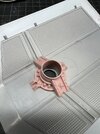
I started by drilling a pilot hole in the wing and then progressively opened it using a step bit by hand. The final size was 5/8" and that was just a smidge too big. I'll be going with 9/16" on the other wing.

IMG_5413.jpg


IMG_5414.jpg


IMG_5438.jpg


Taking a cue from John Simmons at the last minute I decided to leave the greeblies on the connector in place. From there I held my breath and glued the wing connector in place making sure it sat flush with the surface.

IMG_5417.jpg


The Leopold parts were sanded to sneak up on a close to perfect fit. They were glued in place using 5-minute epoxy so that I had a little time to adjust their position.

IMG_5418.jpg


After that it was smooth sailing and fun, gluing on greeblies. The nice part about over coming the hurtle of doing something that there are two of is once one is completed* you have reference for doing the other side. *I still need to do the greeblies on the outside of the wings.

IMG_5422.jpg


For the wing mount covers on the outside of the wings I've added 3mm grub screws like the filming model. These are purely cosmetic. The covers will be held on with magnets.

IMG_5435.jpg


IMG_5437.jpg


On last thing. I got my fuselage bodies back from fellow member mjhenks. He did a great job turning the grooves in them and I can't thank him enough.

IMG_5423.jpg
 

Attachments

  • IMG_5417.jpg
    IMG_5417.jpg
    328.2 KB · Views: 20
Last edited:
The problem with PVC is it doesn't come in an actual 2" diameter.
One thing I found is that the first stage tube in the AMT 1/200 scale Saturn V kit (#AMT846 and issued as early as 1960ish timeframe, according to Scalemates) is exactly 2 inches diameter (OD). Of coures, it has the molded detail that would have to be removed to use it... but it is styrene plastic!
Cheers
 
Thank you for that! I knew it needed to be sanded but not mounted on styrene.

View attachment 1811077
You need that extra material at the sides so that the greebly (which has a flat back) can wrap seamlessly over the curvature of the main body. If you squint your eyes you can see it on the reference picture. Don't quote me on the 1mm measurement, though...it might be 1,5mm.
 
I used 1mm and .75mm (slightly bigger than the Nelson donors).
To be honest they do look a tad oversize in my build.
In any case, they definitively look round to me rather than half-round.
 
i think i found my root of the problems
ring problems.png
the red area witch is not seen in the front or rear view, is inside the thick part, maybe i should have made it green
but u can already see, that not all views are to scale to each other

all views have a main fuselage of 52mm, except the bottom view, wich is smaller, only 51mm
tpbtm problems.png

long story short, watch out your measurements
i have chosen now 21,5mm for the "x"

and Boxcar Bret, witch measurment did u take for the fuselage now, did u find an abs tube of 2 inches(50,8mm)?
will you work with 51mm or 52mm?
witch of both is actualy correct?
 
Last edited:

Your message may be considered spam for the following reasons:

If you wish to reply despite these issues, check the box below before replying.
Be aware that malicious compliance may result in more severe penalties.
Back
Top