5 ft. ANH “Wooden” Falcon

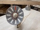
Deviated again on the Falcon. Stinson Lenz’s Full Reverse posting back in 2014 shows excellent knowledge and application of jet engine thrust reverser design.
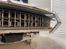
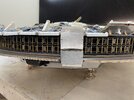
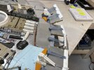
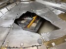
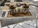
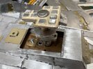
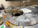
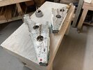
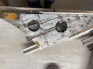
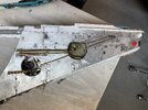
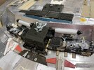
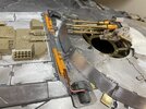
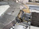
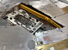
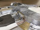
I had to copy his work on one of the engine flaps. Tried to use the flap actuator to the extent practical. Top flap slides back in a set of channels, drops, and then “inverts” at the joint end by “breaking back” the coupling. Bottom flaps follows a similar path.
 

Attachments

  • 18FE37C0-8E0F-4631-AE87-248ECB57FEA3.jpeg
    18FE37C0-8E0F-4631-AE87-248ECB57FEA3.jpeg
    2.9 MB · Views: 164
  • B3EEA7D7-F3E1-4D1C-8DE8-03CD84EF2D22.jpeg
    B3EEA7D7-F3E1-4D1C-8DE8-03CD84EF2D22.jpeg
    3.4 MB · Views: 147
  • 42319CE3-393B-49B5-9546-7CE2884DE7AB.jpeg
    42319CE3-393B-49B5-9546-7CE2884DE7AB.jpeg
    2.7 MB · Views: 156
Working again on the belly of the beast. Yes, it looks like “road kill” with its legs in the air.

Photographs focus on a few things that may be interest.
1. Lifting & flipping method shown using aluminum poles inserted in the airlock ends.
2. Surprisingly, the Chieftain & McLaren skid assemblies easily slide into the disc foot print opening.
3. Trim tabs on the edge of bottom engine flaps.
4. Retractable landing gear carriage bolt nuts that are imbedded into the wood elevator block needs a thrust plate just like the top motor driven end that has a similar thrust strap. This takes the model’s vertical weight when sitting on the landing gear. Note abandoned nose gear nut due to the need to shift from center due to head clearance issue as airfoil goes to reduced thickness at disc edge.
5. Bottom disc armor clad and still playing with gun barrel details.
 

Attachments

  • DE490CC9-9DDC-4BE4-91C6-FD97ECA745DA.jpeg
    DE490CC9-9DDC-4BE4-91C6-FD97ECA745DA.jpeg
    3.1 MB · Views: 151
  • 947958C5-8782-4886-8E5F-5FEDBA33792B.jpeg
    947958C5-8782-4886-8E5F-5FEDBA33792B.jpeg
    3.1 MB · Views: 131
  • DBC84E2C-4B0D-48A8-A93F-BC27EC7D1D22.jpeg
    DBC84E2C-4B0D-48A8-A93F-BC27EC7D1D22.jpeg
    3.1 MB · Views: 124
  • 04D1982B-E8E9-4729-B2A1-35BACD268AD1.jpeg
    04D1982B-E8E9-4729-B2A1-35BACD268AD1.jpeg
    3.7 MB · Views: 118
  • 034517A5-33C5-4BB2-B2A8-5CB5B04D7862.jpeg
    034517A5-33C5-4BB2-B2A8-5CB5B04D7862.jpeg
    3.3 MB · Views: 113
  • C5BD9ED2-68C1-44E8-94D7-EE4D81F9488B.jpeg
    C5BD9ED2-68C1-44E8-94D7-EE4D81F9488B.jpeg
    3.3 MB · Views: 145
Some pictures to show work in progress. More piping on underside of mandibles than on top. Pit work is tedious but rewarding. “Place keeper” kit parts made to insure I can recall penetration locations later when originals or castings obtained and still enable pipe runs.
It is interesting that while the pit tubs I used were precise, about 3”diameter x 5/8” wall height, a little more tolerance is recommended the parts in plan view & height. Scrutiny of wall height shows there is a side wall greeblie in each pit that determines the exact height tub deck to bottom of skin (not armor).
Also shown is progress on the radar. Fortunately for the front of the dish, my kit part supplier’s original and casting parts were of high quality and these defined the layout after a pattern was made and perfectly showed were to carefully score the internal rings that define placement. Only thing I added was the little Lolly Pop circles and wire stems. Also used some thin brass rod to brace the Saturn Cone and SeaLab rings. Back side uses H.O. scale T-rail braces. More work remains. Credit to the original designers for an excellent radar design.
 

Attachments

  • 8DD45648-0322-4742-8EA0-2382D53309EC.jpeg
    8DD45648-0322-4742-8EA0-2382D53309EC.jpeg
    3.5 MB · Views: 130
  • C97DE452-305C-40F2-A07A-7CB1A9536C0B.jpeg
    C97DE452-305C-40F2-A07A-7CB1A9536C0B.jpeg
    1.8 MB · Views: 128
  • 93901703-CC24-40D7-AA6E-8086204F4E5A.jpeg
    93901703-CC24-40D7-AA6E-8086204F4E5A.jpeg
    3.3 MB · Views: 111
  • 56DDADC9-026C-42BE-A90A-7A9DD91A9BAA.jpeg
    56DDADC9-026C-42BE-A90A-7A9DD91A9BAA.jpeg
    1.4 MB · Views: 119
  • 8C4188A7-B8F0-4039-B7C5-CC290B731DBC.jpeg
    8C4188A7-B8F0-4039-B7C5-CC290B731DBC.jpeg
    1.5 MB · Views: 114
  • 24BDE3AC-0488-4FFD-842C-8EE6C70C5496.jpeg
    24BDE3AC-0488-4FFD-842C-8EE6C70C5496.jpeg
    1.7 MB · Views: 115
  • C902A100-414F-45C8-817C-FE80DA09F944.jpeg
    C902A100-414F-45C8-817C-FE80DA09F944.jpeg
    1.8 MB · Views: 109
  • EFAD0515-C932-48AF-A13A-E18DBE3D48B4.jpeg
    EFAD0515-C932-48AF-A13A-E18DBE3D48B4.jpeg
    1.8 MB · Views: 104
  • 7348BF47-8794-4CC0-8BEF-908BA8B237D1.jpeg
    7348BF47-8794-4CC0-8BEF-908BA8B237D1.jpeg
    1.6 MB · Views: 127
Quick few shots from my I-phone. Excuse the dust.
Focus has been on the bottom lately. Temporarily hung the McLaren & Chieftain engine pits on brass rod hangers to check alignment. Placed the Ferrari engines between turret and main landing gear deck. Adjusted bottom turret to sit flush. Airlock inner and outer hatches built and placed on removable disc plates inside docking rings. Place keepers made & markings in place for future kit parts when located.
Lots of fine tuning needed. Even when you think a section is done, one discovers something else. Complex model.
 

Attachments

  • IMG_4014.jpeg
    IMG_4014.jpeg
    3.2 MB · Views: 100
  • IMG_4018.jpeg
    IMG_4018.jpeg
    3.4 MB · Views: 98
  • IMG_4017.jpeg
    IMG_4017.jpeg
    3.2 MB · Views: 82
  • IMG_4016.jpeg
    IMG_4016.jpeg
    2.6 MB · Views: 93
  • IMG_4013.jpeg
    IMG_4013.jpeg
    2.5 MB · Views: 94
  • IMG_4015.jpeg
    IMG_4015.jpeg
    2.8 MB · Views: 104
Man that's beautiful...the fact that you're using a lot of brass for the piping adds the feeling of "This is the construction of the original MF in dry-dock" :cool::cool:(y)(y):notworthy::notworthy:
 
LOVE this update -- the docking ring looks great, and the lower maintenance pits with brightwork look amazing! I don't have the skill, but these shots confirm that metal pipes look a lot better and more "authentic" than squished-when-melted-and-bent Plastruct pipework.

Lovely stuff -- keep it coming.
Thanks SK. Piping, like the metal clad is my thing. That said, styrene armor and styrene piping, properly done, takes an equivalent time and effort. I do not think there is any easy way to do these large kit part creations. Once weathered and painted by a master, the material choice really is impossible to tell. Perhaps when I scratch or sand it the metal will show through, but it’s just me that will know it.
 

Your message may be considered spam for the following reasons:

If you wish to reply despite these issues, check the box below before replying.
Be aware that malicious compliance may result in more severe penalties.
Back
Top