Metro 2033 Volt Driver research/build journal

holtt

Active Member
I'm working on building a reproduction of the Metro 2033 videogame Volt Driver rail gun and thought I'd spin up this thread to post my work log.

I've not seen any other builds from this game, but I personally find the game story and style quite compelling. The game takes place in the Moscow metro underground, 20 years after a nuclear war. Guns and items are manufactured from old scrap and found/salvaged materials. There is a bi of the Fallout aesthetic, minus the retro-future style.

For background on the gun, see Volt Driver - Metro Wiki - Locations, Mutants, Characters, Metro System, Achievements, and more!.

Calculating the Gun Size
The first thing I wanted to do was figure out the size of the gun. I did this two ways: by extracting the game model and calculating size based on game dimensions, and by looking at in-game screenshots.

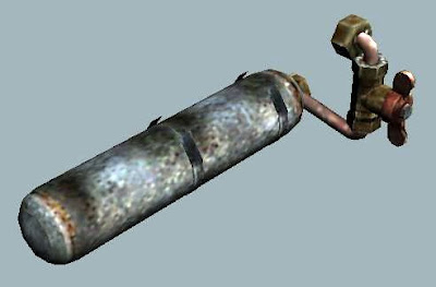
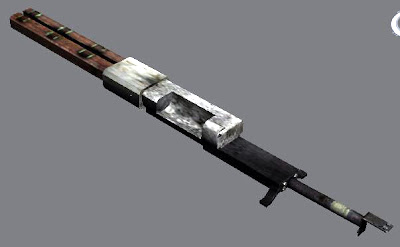
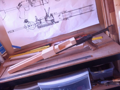
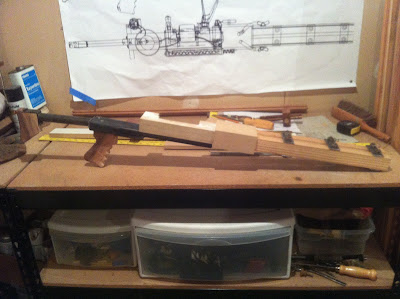
First, here's a set of full sized drawings as extracted from the game content and exported into 3DS Max and then to PDF...

Volt Driver

Based on the game dimensions, the total length of the gun is about 44 inches. Also, when printed full scale, the ball bearings (ammo for the gun) come out to approximately 15mm in diameter, which is their specified size as specified in the game.

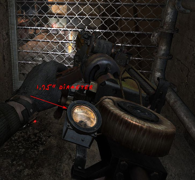
Second, here is a screen shot of an NPC using the gun...

volt_driver_scale_estimate_from_human_dimensions_copy.png


Based on an estimated forearm length of 15", the gun dimensions come out at about 45 inches long.

So - total size, 44 inches long. Based on that, I've now got a full sized set of drawings printed out on an HP DesignJet.


Determining Components
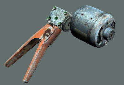
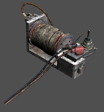
Beyond basic metal and wood structure, the primary distinctive components of the Volt Driver is the integrated charging unit. It is used by the player to charge up the gun. Squeezing a handle runs a small generator, which charges up. The charge level is shown on a small analog panel meter.

I extracted the game textures for the charger, and was able to pull out this distinctive manufacturers plaque that is on the motor...

motor_label.png
.

Additional searching on the web (based on a translation of some text on the label) led me to this picture on a "for sale" site in Ukraine...

74308553_1_644x461_prodam-elektromotor-mun-2-odessa.jpg


Bingo - the same motor label, but with a different serial number. It's a "Universal Motor", and used on industrial sewing machines I believe. I also think it's the same design as a Bodine Universal Motor. Here's one on eBay...

Vintage Bench Tested Bodine 1 8 HP 1 7 Amps 115 Volt AC Motor Type Sub XAL | eBay

Unfortunately the seller for the one in Ukraine wants about $70 for the motor, which is a bit steep. But more importantly, I don't think that the motor itself is the same scale in the game. I think the designers used it as a model, but reduced the size a bit for artistic purposes.

So that makes me think I should just fake one to get the scale right, and use the photo references for the real label as a guide to make my own.

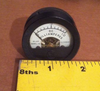
Next up, the little panel meter that shows the charge of the gun. It's smaller than most panel meters, but I was able to find this one on eBay that was the right size, but also old USSR (CCCP) era, completely with Cyrillic lettering. The only downside is that the panel front is not quite the same style, with a square bezel instead of round.

[img=400x400]http://i162.photobucket.com/albums/t255/wlad2007/amper-volt/P6030018.jpg[/img]

Ordered and awaiting delivery! An important detail on this one is the lower DC milliAmp range, meaning I can drive it with an Arduino to get a full "charge" effect, complete with a drop in charge (on the meter) after every shot.

What's Next
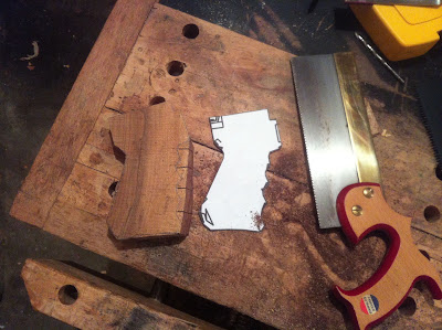
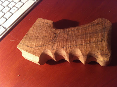
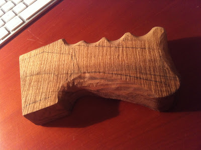
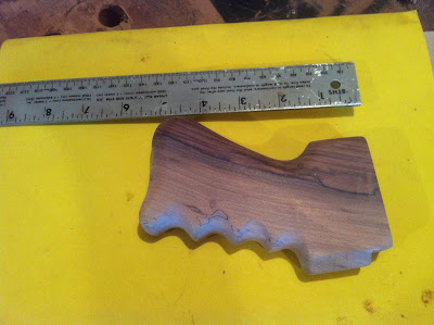
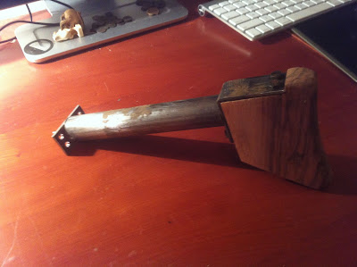
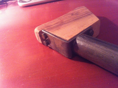
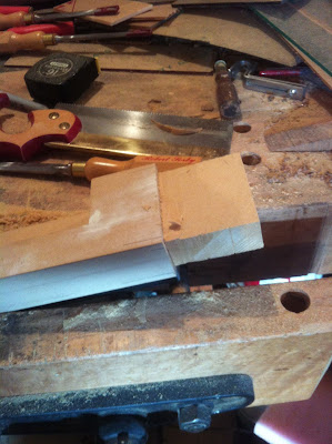
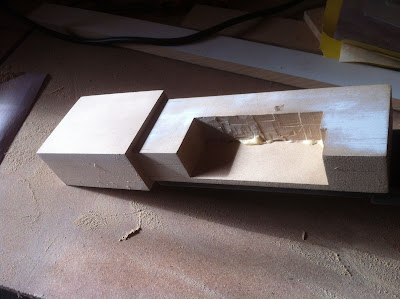
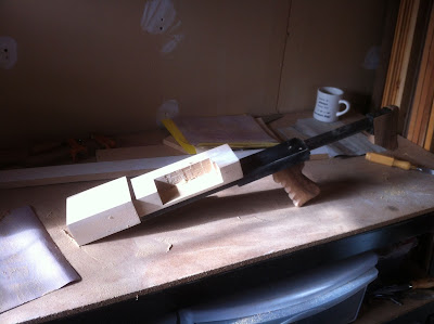
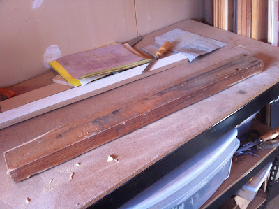
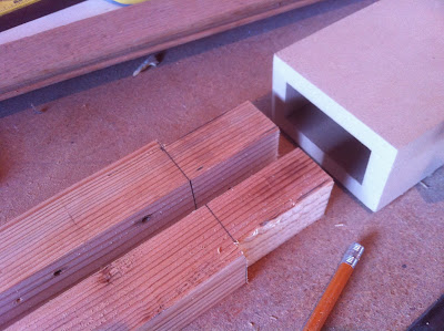
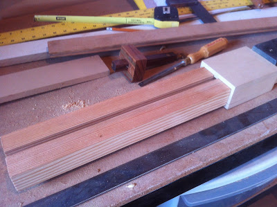
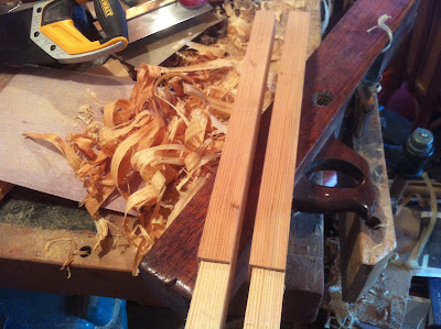
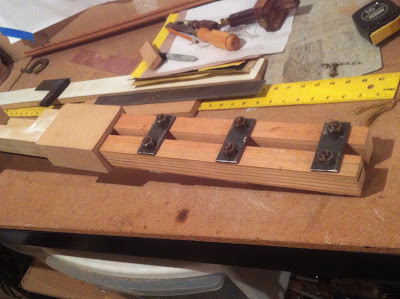
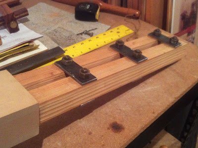
I've been gathering bits of old weathered wood that have that darkened look of the gun's wood components. I'll need that for the main barrel plus stock and grip. It looks a lot like old fir that's been in a garage or attic for a long time. Not weathered, but definitely darkened.

I'm also making a dimensions list to find metal components needed. Like most everything in the game, things need to look very weathered and used. This wasn't something made in a factory, but from "found stuff" down in the Moscow metro tunnels and old surface factories.

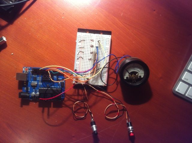
The other thing is to start thinking about electronics. I'm thinking I'll make an Arduino board a core component for this. The Arduino can drive the small charge panel meter, and pumping the charger can simulate it charging up, plus pulling the trigger can simulate the charge dropping.

Additionally, I think I can put a set of blue LEDs inside the main gun barrel area, and trigger a bright blue flash along with sound FX on hitting the trigger. Ought to look nice.

Still To Find
Right now I'd love to find a bunch of old 15mm ball bearings. Specifically not new ones, but old crusty ones. I suppose I could buy new and tumble them around in some gravel and mud to weather them.
 
Last edited:
Just put up a set of reference shots from one of the game models into the galleries. There's no Metro 2033 section so it's just in "general"
 
Picked up a new part for my Metro 2033 Volt Driver gun build. A small analog meter that has the right values to let me drive it with an Arduino. The meter on the Volt Driver indicates your gun's current charge. Here's an in-game picture of the meter, which is lit by a faint amber glow...

VoltDriver_meter_1.jpg


The meter on the Volt Driver is 1.75" in diameter, which is abnormally small at least for older meters. Most any old analog meter you find is going to be 3" or so in diameter. That said, there are variations, like in this picture of a few I have in my collection...

IMG_3138.JPG


The one on the left is typical size, and the rest are smaller than the usual mix, including that tiny little 1" one on the far right. I don't have a project for it yet but it's going to be used on something interesting someday.

The one I bought for the Volt Driver is second from the right above. It's a DeJUR model 112, with a 0-10 milliampers scale. Here's a closeup...

IMG_3134.JPG


It's unfortunately not 100% exactly the same face layout, but is at least the same size. However the flat bit that obscures the bottom of the meter does come out and can be modified to a new shape to match the original.

I could fake up a full meter, but I really want it to be operational and be driven by the on-board Arduino.

The one thing this meter doesn't have is an integrated light. I'll have to see if I can figure out how to add a very small amber LED to do that, or may end up skipping that part if it means excessive modification that might damage the meter.

If anyone's interested in doing things with these kinds of meters, here's one little trick. If you get one that has a range of about 0-25 milliamp DC, it's just about right for hooking up to something that's normally got an LED on it. For example, they look awesome in a computer case if wired up to the disk activity light, with the needle flicking on each disk access. If you want to get into specialized movement of the needle (like being able to incrementally position it), you'll need to drive it with an Arduino or something like that.
 
I've breadboarded up the Arduino-based FX controller for the Volt Driver gun to start programming the whole fire, charge sequence as well as LED and meter control.

arduino_volt_driver_mockup_2.jpg


I've taken taken a video of it in action that shows how the charge level is indicated on the panel meter, buttons charge and fire, and LEDs pulse on firing.

https://vimeo.com/55348692

Basically, the Arduino models the charging and firing of the gun by monitoring two pushbuttons (Fire and Charge), and lighting up a series of LEDs, plus controlling the analog panel meter's needle location to show current charge level. Here are a few details...

  • The gun can hold up to 18 charges.
  • The current charge level is shown on small analog meter, which is controlled by the Arduino. The meter is a rarer small one (1.75"), with a 10 DC milliamperes range.
  • Each press of the "Charge" button adds one charge, up to the maximum of 18.
  • Each press of the "Fire" button fires the gun once, using up one charge. There is a 1/2 second delay until another shot is possible (to be adjusted).
  • When fired, the LEDs are lit up in rapid succession. They will be inside the gun's main barrel "rail" and simulate the firing of the rail gun.
  • Final version will use blue and/or white LEDs for better "electrical" look. I happen to have a ton of green ones on hand.
 
I played with my arduino stuff yesterday and got something working out from stepper motor, which produces AC voltage when turned. here is my idea for real working "dynamo", the mA meter is still open to me, even if im electrician myself. but here is something to get you started for creating "METRO 2033" dynamo or even making this volt driver run with hand made electricity;)

Click for bigger picture
I tried this on breadboard with really big capasitors (3300uF) and led+mA meter, and got the led lit up with hard turning of the stepper motors tiny axle. When there was no load, the capasitor got about 3V-7V of voltage stored when i rotated the motor for 15-20seconds. Hope someone makes this better and uses some kind battery to work on his/her replicas :)

Camera_ZOOM_20121216205226663.jpg

Camera_ZOOM_20121216205239892.jpg


Keep the good work up! ;)
 
Last edited:
etsdriver, that's pretty neat! Thanks for posting.

I hadn't thought about actually charging up a real capacitor like that, but it would make it more interesting. A smaller motor like you show inside rigged up to the dynamo unit would certainly be possible.
 
etsdriver, that's pretty neat! Thanks for posting.

I hadn't thought about actually charging up a real capacitor like that, but it would make it more interesting. A smaller motor like you show inside rigged up to the dynamo unit would certainly be possible.

Last night i again played with these ideas and with stepper motor made by MITSUMI, model M49SP-2K, I was able to load old radio PSU electrolytic capasitor (Nippon Chemicon, 10 000uF, 50V) with tiny rotation up to 7V easy. One problem here is that the loading charge is pretty low, 1-40mA only, so it would take forever to charge 1200mAh accu-battery at 1.2V. Arduino can take 5V and with little bit more of electronics the idea is nice, ill look forward about improving this or actually making real "dynamo" for loading big cap-bank(1Farands/2Farands).

But as SAFETY note: remeber, the capasitors must always be decharged by some load, shortcircuiting them makes nice bang, but the power does not feel nice in fingers, and it isnt good for caps too. ;)
 
Another update.

Now that I've got the basics of the electronics worked out with the Arduino to drive the charge meter and switching setup, I thought I'd move to some wood working for contrast.

A screenshot from the original game's gun model to start with...

stock.jpg


The grip and butt stock on the gun are both wood. I had a scrap of walnut form a tree I'd cut down once that was the right thickness (full 1") so used it.

On to the construction. First, making the grip...

Rough form
IMG_3243.JPG


Some shaping with sandpaper and knife
IMG_3251.JPG


Other side
IMG_3253.JPG


Sanded smooth
IMG_3262.JPG


The butt stock with metal bracket attached to the pipe which will attach to the main body of the gun...

IMG_3264.JPG


IMG_3266.JPG


Unfortunately the wood I had was too nice - doesn't quite match the gritty nature of the game style. I very well may remake it with something not as "pretty", though the walnut does look good I must say.

Still need to apply some checkering (that hash pattern) to the grip sides. Also perhaps a metal plate on the side of the butt like in the original. It appears that this is supposed to be a patch to fix a crack in the wood. I don't want to put a real crack in it but could at least fake it a bit.

Next up is blocking out the main body and the barrel. I actually removed and replaced a piece of a 2x4 from my garage wall which is nicely aged the right color for the main barrel.
 
Last edited:
The maple does look pretty good. You could fake the crack a bit using a file to file a bit and then put the patch on it. You could age the wood too and beat it up a bit to make it look older like furniture makers do with replacement parts.
 
The maple does look pretty good. You could fake the crack a bit using a file to file a bit and then put the patch on it. You could age the wood too and beat it up a bit to make it look older like furniture makers do with replacement parts.

Was thinking about that. One thing I'm finding is that there are some design issues with the gun as it is modeled in the game, versus physically how it actually goes together.

For example there is a spot in the main body where a side valve/gizmo is actually offset from where it really would be - I presume so that when in first person view, it is visually balanced with other elements of the gun's structure. It's only when you look at the extracted 3d models do you see how it's actually not correct.

One good thing though is that there are two models of the gun in the game - one for user (FP view), and one as a prop. The prop one is physically different than the users's version (users has more details), but the prop one doesn't fudge layout for better FP look.
 
Your project looks like it is coming along really well. I'm also interested in constructing a model of the volt driver although I'm trying to construct a working one. According to the Metro Wiki it isn't possible, but I have yet to finish all the calculations to confirm this. So far, the math is saying it's possible to get one shot before recharging, and have the projectile go 150 feet. I still need to figure out how long it would take to charge the capacitors using the hand crank, and see if it's realistic. I have a feeling to get this to work in the end it's going to be looking significantly different from the model. Anyway, the pictures you posted with dimensions proved to be very useful so thank you for those.

I'm curious as to which model you actually plan on constructing, the first-person model or the third-person one? Also, do plan on constructing the rails 0.5" apart even though this is smaller than the 15 mm (~0.59") projectile? And lastly did you find a generator (motor) of the correct dimensions yet?
 
I'm curious as to which model you actually plan on constructing, the first-person model or the third-person one? Also, do plan on constructing the rails 0.5" apart even though this is smaller than the 15 mm (~0.59") projectile? And lastly did you find a generator (motor) of the correct dimensions yet?

The first person one, as I think it's a bit more interesting, especially with the meter!

As to rail spacing, I was thinking of doing it with the 1/2" spacing, but to open up a groove in the inside that would theoretically accommodate the 15mm ball bearings.

I haven't yet found a motor of the correct size alas. Based on some drawings with dimensions of the real motor (the "МУН-2"), I think it's actually bigger than in-game by a bit. If it wasn't so spendy I'd love to just pick up the one at ?????? ???????????? ???-2 - ?????? ? ?????? ?? Slando for the label. I'll probably just create a fake one for the first pass, but would like to ideally get the gears and such working with the generator handle and to get the gears spinning and such.

I've got a bunch of new screens of the FP model sub-elements I took in 3ds Max with the imported model. I put in a request for a new "Metro 2033" gallery under Video Games as I didn't want to keep cluttering up the uncategorized area. In the mean time here's a link to a picture gallery on Google, which I think is accessible...

https://picasaweb.google.com/106684972972566758773/Metro2033VoltDriver
 
Last edited:
Wow, those pics are awesome. Thank so much for posting them. That picasa album is proving to be very useful is deciphering how accurately a working model can be constructed from the video game model.

How exactly are you getting the dimensions of all the parts? I'm trying to find the dimensions of the generator, and some of the body pieces. Any help would be appreciated.

Why did you choose to go with a current meter versus a voltage one? I can't quite tell in game what it is, but I imagined it would be a volt meter somehow connected to a hidden capacitor in the body.

No problem. I've got the models imported into 3ds Max so am able to take screens from various angles, hide elements of the model, etc. Pretty useful.

For dimensions, I have created a full sized PNG file showing top/side/front views of the gun from the 3ds Max views. It's kind of cluttered with a lot of line overlay but one can get dimensions from this. If you go back to the Picasa album, I've added the image. I think you can access it directly via https://picasaweb.google.com/lh/photo/l-FR4-QWpjxwbvsOTEC1RNMTjNZETYmyPJy0liipFm0

RE: the meter choice. I went with a DC milliamp range meter as I've had some experience using them in a PC hooked up to an LED circuit. Also I'm able to directly drive it with the Arduino with out any problem, and explicitly position the needle at any location I want. Technically yes it's not the correct scale (milliamps vs volts), but as you say the in-game one isn't specific.

The real challenge with meters is finding one the right size (1 3/4" diameter). That's a pretty rare size. Actually, a few lots of real Soviet era ones came up on eBay the other day that are also the right size. See Russian Panel Meter DC 50MKA M4206 NOS Lot of 1 | eBay. It's not exactly the right shape to match the model perfectly, but the size and scale are just right. In fact the meter on the in-game model isn't really based on a real meter as far as I can tell - the back looks more like a small speaker, without the cylindrical "can" body one normally sees on the back of the meter.

New post in a bit with more construction pictures...
 
Last edited:
Thanks for the extra pictures. They've helped me break the gun down into all the parts but I think it's time I import the model into a CAD program myself so I won't be constantly bugging you for dimensions. I've managed to unpack all the files using the Metro unpacker but now I'm stuck on what to do. I tried placing some .dli plugins for the 3ds max 2012 in the plugins folder but I still couldn't get any of the files to open. It may be because I'm using the 2013 trial version. How were you able to port the models?

By the way I was looking at the some of the latest updates in the picasa album. The body of the gun looks like it's coming along nicely.

Edit: Using a different version of the program worked. But measuring is proving difficult.

Sorry for the late reply. I also had problems with a newer version of 3ds Max. Works with my copy of 2010 though. One thing that took a bit of time was finding the actual gun model's from first person mode - they are down in meshes/dynamic/hud/weapons.

A couple of updated pictures here. I glued up a "box" of 1/2" MDF for the piece where the body and the front rails meet...

IMG_3301.JPG


I did it as an empty box, plus purposely made the main body longer than is actually visible. That way I could make the main body a tenon that would just fit into the box. Nice and strong that way. Here's the sequence of marking and cutting out the tenon end.

Marked...
IMG_3302.JPG


Cut...
IMG_3303.JPG


Fit together...
IMG_3304.JPG


The overall gun so far...
IMG_3306.JPG


Next up is beveling the new box piece, plus make the two wooden rails that come out the front of the box. They will also slide inside the end for good strength.

Overall I'm hoping to put some screws in the bottom to hold it together so that it can be taken down for travel & storage.
 
I went ahead and knocked out the main front rails (the "barrel" I guess you'd call it) today. Here's the build steps...

First, the wood I'm using - an old 2x4 that's got a bit of age/color/character...
IMG_3309.JPG


Cut into two pieces the right dimensions
IMG_3311.JPG


Like the main body, they are cut smaller to fit into the box joint between body and barrel...
IMG_3312.JPG


Test fit...
IMG_3314.JPG


IMG_3316.JPG


Some correction with a hand plane...
IMG_3317.JPG


Then I cut and added the 1/8" metal pieces that hold it together with the bolts...
IMG_3326.JPG


IMG_3327.JPG


The overall gun so far...
IMG_3324.JPG


With it all together I was able to heft it up, and I gotta say this thing is heavy. At 4 inches shy of 4 feet long, it's no compact weapon!
 
I went ahead and knocked out the main front rails (the "barrel" I guess you'd call it) today. Here's the build steps...

With it all together I was able to heft it up, and I gotta say this thing is heavy. At 4 inches shy of 4 feet long, it's no compact weapon!

No doubt.
That toroidal transformer on top, the one that looks like a doughnut or an ammo drum? Those things aren't light, being a large chunk of metal wrapped in two coils of copper wire. A round one that size would probably weigh as much as all your other components put together plus some, not to mention making the whole rig top-heavy and unwieldy.
 
This thread is more than 9 years old.

Your message may be considered spam for the following reasons:

  1. This thread hasn't been active in some time. A new post in this thread might not contribute constructively to this discussion after so long.
If you wish to reply despite these issues, check the box below before replying.
Be aware that malicious compliance may result in more severe penalties.
Back
Top