Man, that MR Makototsai style LED setup looks like it'd be perfect for the outer ring. And it looks like it would work with a more static approach (all on, all off) if you didn't want to go with the ladder setup.
I know we all want it to light up in succession since that's what it did in that first Tron Legacy visual effects trailer, but the recent trailers don't even show it lighting up succession style. More recent footage just kind of show it "bursting" on all at once.
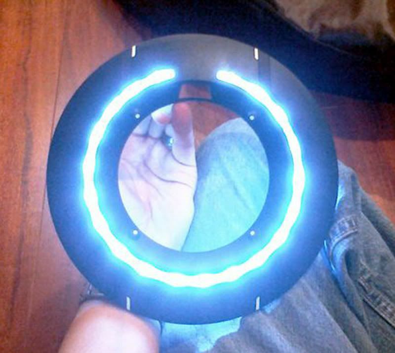
Recalling the image blackfeathers posted...
... I wonder how easy it'd be to set up two separate strings. Please note the light pattern on the outer ring. I'm not saying this is the actual setup, but it looks like a similar setup would be a "3 on, 1 off" kind of pattern. So if you set it up with LEDs, you'd have three LEDs on, then on LED off, and repeat that all the way around.
So I'm wondering here if - in order to achieve the "burst on" effect - if you could make it so you have two separate strings: one string has sets of three LEDs setup to all turn on at once and stay on, and the other string would have single LEDs setup in the spaces between the sets of three to turn on momentarily at the same time the other string turns on, but then turns off a moment later. That way, momentarily, all of them are on and then every 4th LED turns off. If you use super bright LEDs, I would think that you could get a decent-enough "burst on" effect.
Keep in mind, this is coming from someone that doesn't know how to actually set this stuff up, so it may not even be feasible.
Thoughts?
")