I don't know what the interest is on the timers from Sliders anymore, but considering that there hasn't been that much information about the reproduction of it provided online publicly, I figured that I should move all the info that I have to a thread here.
This mainly pertains to the Original Timer, but a lot of the resources can be, and will be converted for use with the other timer models.
A few files linked to Google Drive, for lack of a better place to upload files, so if there is any problem with the links or downloads, let me know.
__________________________________________________________________________________________________________________________
Faceplate Design Files
Original Timer Faceplate Design PDF Files download link here.
Upon doing some tangible sizing, I see now that this version of the faceplate is going to be too short for this build of the timer presented in the post. I am leaving the source files up in case anyone wants to edit them for their project for the time being. I will be updating them with the correct sizing as soon as I have the timer closer to completion. Then I will know the actual size that the faceplate should be.
__________________________________________________________________________________________________________________________
Electronic Parts List
This list is only the electronic components.
Starting from the top down:
Emitter LEDs:
High Intensity White LED
Two of these should do the trick.
Days Display:
0.3" Single Digit Display
I figured that these would work as they are slightly smaller than the main digit displays. It has been very tricky to track down a display that has three digits that fit the dimensions needed. Anyone have any other ideas?
Potentiometer (for the dial):
Sparkfun Thumbwheel Potentiometer
A thumbwheel pot is probably the best option for the knob on the original timer because of the low profile size of it. The original timer does not have much clearance under the black box, especially given that the knob is recessed into the enclosure.
I'm going to have to modify the thumbwheel to secure onto the knob, but that should be fairly simple to do.
Display drivers/multiplexers: EDIT: It seems that this link now goes to the thru-hole version of the IC, but I surface mount version will need to be used instead. Link has been updated for the SMT MAX7221 from Digikey.
MAX7219 - Eight Digit Display Driver
Two of these are needed for full functionality. I used the MAX7221, but these MAX7219's are more common and cheaper.
The main HH:MM:SS digit display:
0.36" Single Digit Display
These are single digits and should fit perfectly with the given dimensions. I am using the common cathode version because the MAX72xx chips require common cathode displays.
Colon LEDs:
Small Rectangular Red LEDs
Bargraph Displays:
10 Segment Green Bargraph Display
I like to use Sparkfun whenever I can because they have all the EagleCad libraries for all of their products, making it much easier to make a PCB design.
Tau/Zeta/Delta LEDs:
Rectangular 5mm x 2mm Color LED
Rectangular 5mm x 2mm Color LED
Rectangular 5mm x 2mm Color LED
Buttons:
I've decided on which button type to use. These will work great with eh dimensions needed.
Tactile Button Switches
New: USB micro SMD Connector:
Micro USB SMD Connector
So that I can interface with the timer through the bottom port directly to the computer and reprogram the timer without having to dismantle it.
MCU:
Arduino Micro Board
The main processor for the entire rig. I chose this because its small and can just be incorporated into the design, as-is, and simplifies things a lot, and has more analogue inputs than most of the small Arduino boards.
The circuit make-up will require some resistors and some capacitors and Sparkfun has the correct types:
330 Ohm SMD Resistors
100nF SMD Capacitors
10uF SMD Capacitors
Additional update: I have added some 1k ohm surface mount resistors for the LEDs that are constantly powered on the bargraphs
You can order them in a small quantity from DigiKey.com.
Green LEDs tend to be brighter in comparison to the power provided as compared to the other LEDs.
There will also be two other types of resistors for the current resistors that go with each display driver. Each resistor type will be of different value due to using three different display types (green bargraphs, main red HH:MM:SS display, and red days display, where the days display will have a different current rating than the main HH:MM:SS display, and the two different colors, red and green, will also have different current ratings because of the color difference).
I will have those resistor ratings later and I will post links to where to get them. I have a space on the PCB to place a socket for the resistors, and I'll figure out the best current limiting resistor for the displays after getting PCB installed under the faceplate, for best brightness and power consumption.
Pictures of many of the parts:
http://i71.servimg.com/u/f71/18/36/28/14/bgandb10.jpg
http://i71.servimg.com/u/f71/18/36/28/14/displa10.jpg
http://i71.servimg.com/u/f71/18/36/28/14/everyt10.jpg
I've tried to keep the entire circuit as simple as possible to keep the parts list to a bare minimum. One of the huge advantages to using the MAX72xx display drivers is that the current limiting is left up to a single Rset resistor because of the nature of multiplexing. So this really reduces the component count.
Now this is just the electronic components that I have figured out so far (mostly), but some are subject to change, and some, like the buttons, aren't entirely figured out quite yet. The enclosure and cosmetic parts list will be a separate section. Hopefully some experienced timer builders may have some suggestions for additions or changes.
_________________________________________________________________________________________________________________________
PCB Printing
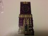
The PCB that I have currently designed out I have currently ordered from oshpark.com and I'm waiting for it to be shipped to me.
Currently the PCB will look like this(front) and (back).
Source board files provided here.
Oshpark.com Shared Project page for the PCB here (older version without jumper connection and other improvements). : From here, you can order the most current board that I've developed so far.
Update: New board version HERE. I incorporated a line of jumper connections that connect the top of the board to the bottom, making room for better PCB wire routing. This frees up some mess in the HH:MM:SS area of the PCB enabling the proper use of through-hole component placement. I also moved the bargraphs and three LEDs down a tad to make it more screen accurate.
I kept the original PCB without jumper connection available above, but as long as everything works on the newer version, I suggest using the update version.
__________________________________________________________________________________________________________________________
Current Source Code (not complete)
The source code for the MCU is not complete yet because I have to decide how I am going to manage the battery power and the on/off function of it once I have the case made, but the input/output hardware is solid, and I have a microUSB connection on the bottom of the PCB that is accessible from the battery charger port on the Motorola phone case to reprogram the MCU without having to disassemble anything.
Video of the components in action on the breadboard:
The video includes the basic functions of the program but doesn't include the input to reset the time and such. I used the Arduino platform, so the code is main in C based off of the Arduino IDE and used the Arduino LED Control library.
Code here.
If anyone recalls, I incorporated some of the code provided by Steven Genser on these forums; its kind of a novelty to have a virtual piece of the original prop included into it.
__________________________________________________________________________________________________________________________
Anyways, I figured that I would post what I have here because I see Sliders Timer topics pop up once in a while that only has the usual big plans that are never realized, or just pictures of already made prop replicas. Also the forum that I was posting this stuff on seemed to die off a bit. If anyone is interested, the original post was on Xslider13's timer forums.
This mainly pertains to the Original Timer, but a lot of the resources can be, and will be converted for use with the other timer models.
A few files linked to Google Drive, for lack of a better place to upload files, so if there is any problem with the links or downloads, let me know.
__________________________________________________________________________________________________________________________
Faceplate Design Files
Original Timer Faceplate Design PDF Files download link here.
Upon doing some tangible sizing, I see now that this version of the faceplate is going to be too short for this build of the timer presented in the post. I am leaving the source files up in case anyone wants to edit them for their project for the time being. I will be updating them with the correct sizing as soon as I have the timer closer to completion. Then I will know the actual size that the faceplate should be.
__________________________________________________________________________________________________________________________
Electronic Parts List
This list is only the electronic components.
Starting from the top down:
Emitter LEDs:
High Intensity White LED
Two of these should do the trick.
Days Display:
0.3" Single Digit Display
I figured that these would work as they are slightly smaller than the main digit displays. It has been very tricky to track down a display that has three digits that fit the dimensions needed. Anyone have any other ideas?
Potentiometer (for the dial):
Sparkfun Thumbwheel Potentiometer
A thumbwheel pot is probably the best option for the knob on the original timer because of the low profile size of it. The original timer does not have much clearance under the black box, especially given that the knob is recessed into the enclosure.
I'm going to have to modify the thumbwheel to secure onto the knob, but that should be fairly simple to do.
Display drivers/multiplexers: EDIT: It seems that this link now goes to the thru-hole version of the IC, but I surface mount version will need to be used instead. Link has been updated for the SMT MAX7221 from Digikey.
MAX7219 - Eight Digit Display Driver
Two of these are needed for full functionality. I used the MAX7221, but these MAX7219's are more common and cheaper.
The main HH:MM:SS digit display:
0.36" Single Digit Display
These are single digits and should fit perfectly with the given dimensions. I am using the common cathode version because the MAX72xx chips require common cathode displays.
Colon LEDs:
Small Rectangular Red LEDs
Bargraph Displays:
10 Segment Green Bargraph Display
I like to use Sparkfun whenever I can because they have all the EagleCad libraries for all of their products, making it much easier to make a PCB design.
Tau/Zeta/Delta LEDs:
Rectangular 5mm x 2mm Color LED
Rectangular 5mm x 2mm Color LED
Rectangular 5mm x 2mm Color LED
Buttons:
I've decided on which button type to use. These will work great with eh dimensions needed.
Tactile Button Switches
New: USB micro SMD Connector:
Micro USB SMD Connector
So that I can interface with the timer through the bottom port directly to the computer and reprogram the timer without having to dismantle it.
MCU:
Arduino Micro Board
The main processor for the entire rig. I chose this because its small and can just be incorporated into the design, as-is, and simplifies things a lot, and has more analogue inputs than most of the small Arduino boards.
The circuit make-up will require some resistors and some capacitors and Sparkfun has the correct types:
330 Ohm SMD Resistors
100nF SMD Capacitors
10uF SMD Capacitors
Additional update: I have added some 1k ohm surface mount resistors for the LEDs that are constantly powered on the bargraphs
You can order them in a small quantity from DigiKey.com.
Green LEDs tend to be brighter in comparison to the power provided as compared to the other LEDs.
There will also be two other types of resistors for the current resistors that go with each display driver. Each resistor type will be of different value due to using three different display types (green bargraphs, main red HH:MM:SS display, and red days display, where the days display will have a different current rating than the main HH:MM:SS display, and the two different colors, red and green, will also have different current ratings because of the color difference).
I will have those resistor ratings later and I will post links to where to get them. I have a space on the PCB to place a socket for the resistors, and I'll figure out the best current limiting resistor for the displays after getting PCB installed under the faceplate, for best brightness and power consumption.
Pictures of many of the parts:
http://i71.servimg.com/u/f71/18/36/28/14/bgandb10.jpg
http://i71.servimg.com/u/f71/18/36/28/14/displa10.jpg
http://i71.servimg.com/u/f71/18/36/28/14/everyt10.jpg
I've tried to keep the entire circuit as simple as possible to keep the parts list to a bare minimum. One of the huge advantages to using the MAX72xx display drivers is that the current limiting is left up to a single Rset resistor because of the nature of multiplexing. So this really reduces the component count.
Now this is just the electronic components that I have figured out so far (mostly), but some are subject to change, and some, like the buttons, aren't entirely figured out quite yet. The enclosure and cosmetic parts list will be a separate section. Hopefully some experienced timer builders may have some suggestions for additions or changes.
_________________________________________________________________________________________________________________________
PCB Printing
The PCB that I have currently designed out I have currently ordered from oshpark.com and I'm waiting for it to be shipped to me.
Currently the PCB will look like this(front) and (back).
Source board files provided here.
Oshpark.com Shared Project page for the PCB here (older version without jumper connection and other improvements). : From here, you can order the most current board that I've developed so far.
Update: New board version HERE. I incorporated a line of jumper connections that connect the top of the board to the bottom, making room for better PCB wire routing. This frees up some mess in the HH:MM:SS area of the PCB enabling the proper use of through-hole component placement. I also moved the bargraphs and three LEDs down a tad to make it more screen accurate.
I kept the original PCB without jumper connection available above, but as long as everything works on the newer version, I suggest using the update version.
__________________________________________________________________________________________________________________________
Current Source Code (not complete)
The source code for the MCU is not complete yet because I have to decide how I am going to manage the battery power and the on/off function of it once I have the case made, but the input/output hardware is solid, and I have a microUSB connection on the bottom of the PCB that is accessible from the battery charger port on the Motorola phone case to reprogram the MCU without having to disassemble anything.
Video of the components in action on the breadboard:
The video includes the basic functions of the program but doesn't include the input to reset the time and such. I used the Arduino platform, so the code is main in C based off of the Arduino IDE and used the Arduino LED Control library.
Code here.
Code:
#include "LedControl.h"
/*
pin 12 DataIn
pin 11  CLK
pin 10 LOAD
Two MAX7221's
*/
LedControl lc=LedControl(12,11,10,2);


//buttons and inputs
const int button0 = A0;
const int button1 = A1;
const int button2 = A2;
const int button3 = A3;
const int pot1 = A4;
const int greenpin = 5; //green LED
const int redpin = 6; //red LED
const int yellowpin = 8; //yellow LED
const int emitters = 3; //emitters are connected in serial
const int speaker = 4; //piezo
const int colons =  13; //colons are connected in serial

unsigned long totalsectime = 35; //this value is the beginning countdown time
//totalsectime will later be filled in by time set function by inputs

void setup() {
 randomSeed(analogRead(A5)); //sets pin A5 as an input to generate a random number
 pinMode(colons, OUTPUT);
 pinMode(speaker, OUTPUT);
 pinMode(emitters, OUTPUT);
 pinMode(button0, INPUT);
 pinMode(button1, INPUT);
 pinMode(button2, INPUT);
 pinMode(button3, INPUT);
 pinMode(pot1, INPUT);
 pinMode(greenpin, OUTPUT);
 pinMode(redpin, OUTPUT);
 pinMode(yellowpin, OUTPUT);

 // number of devices LedControl
 int devices=lc.getDeviceCount();
 //init all devices in a loop
 for(int address=0;address<devices;address++) {
   //take out of power saving mode
   lc.shutdown(address,false);
   // set brightness - depends on Rset values
   lc.setIntensity(0,15);
   lc.setIntensity(1,1);
   /* and clear the display */
   lc.clearDisplay(address);
   //sets the number of digits that each 7221 will scan through when multiplexing
   lc.setScanLimit(0, 6);
   lc.setScanLimit(1, 6);
 }
}

//COLON BLINK FUNCTION for normal countdown 2 blink/second
int colonsState = LOW;
long previouscolonsMillis = 0;
long colonsinterval = 250;
void colonBlink(){

 unsigned long currentcolonsMillis = millis();

 if(currentcolonsMillis - previouscolonsMillis > colonsinterval) {
   // save the last time you blinked the LED
   previouscolonsMillis = currentcolonsMillis;

   // if the LED is off turn it on and vice-versa:
   if (colonsState == LOW)
     colonsState = HIGH;
   else
     colonsState = LOW;

   // set the LED with the ledState of the variable:
   digitalWrite(colons, colonsState);
 }
}

//GENSER SEQUENCE PREAMBLE
void genserOne() {
 //GEnSEr
 //G
 lc.setRow(0,0,B01011110);
 //E
 lc.setChar(0,1,'E',false);
 //n
 lc.setRow(0,2,0x15);
 //S(5)
 lc.setChar(0,3,'5',false);
 //E
 lc.setChar(0,4,'E',false);
 //r
 lc.setRow(0,5,0x05);

 delay(400);
 //clear
 lc.clearDisplay(0);
 delay(40);

 //random 1
 lc.setRow(0,0,B01001001);

 lc.setRow(0,1,B00010101);

 lc.setRow(0,2,B00100011);

 lc.setRow(0,3,B00000011);

 lc.setRow(0,4,B01010100);

 lc.setRow(0,5,B01000011);

 delay(200);
 //clear
 lc.clearDisplay(0);
 delay(40);

 //CAluri
 //C
 lc.setRow(0,0,B01001110);
 //A
 lc.setChar (0,1,'A',false);
 //l(lowercase "L")
 lc.setRow(0,2,B00110000);
 //u
 lc.setRow(0,3,B00011100);
 //r
 lc.setRow(0,4,B00000101);
 //i
 lc.setRow(0,5,B00010000);

 delay(200);
 //clear
 lc.clearDisplay(0);
 delay(40);

 //4th Sequence
 lc.setRow(0,0,B00100011);

 lc.setRow(0,1,B00000011);

 lc.setRow(0,2,B01010100);

 lc.setRow(0,3,B01000011);

 lc.setRow(0,4,B00010011);

 lc.setRow(0,5,B00011001);

 delay(200);
 //clear
 lc.clearDisplay(0);
 delay(40);

 //Second CAluri sequence
 //C
 lc.setRow(0,0,B01001110);
 //A
 lc.setChar (0,1,'A',false);
 //l(lowercase "L")
 lc.setRow(0,2,B00110000);
 //u
 lc.setRow(0,3,B00011100);
 //r
 lc.setRow(0,4,B00000101);
 //i
 lc.setRow(0,5,B00010000);

 delay(200);
 //clear
 lc.clearDisplay(0);
 delay(40);

 //6th Sequence
 lc.setRow(0,0,B00101010);

 lc.setRow(0,1,B00000011);

 lc.setRow(0,2,B00011010);

 lc.setRow(0,3,B01001000);

 lc.setRow(0,4,B01000001);

 lc.setRow(0,5,B01001001);

 delay(200);
 //clear
 lc.clearDisplay(0);
 delay(40);

 //6th Sequence
 lc.setRow(0,0,B00010011);

 lc.setRow(0,1,B00011001);

 lc.setRow(0,2,B00100010);

 lc.setRow(0,3,B00011000);

 lc.setRow(0,4,B01000001);

 lc.setRow(0,5,B00100101);

 delay(250);
 //clear
 lc.clearDisplay(0);
 delay(75);
}


void displayFade() {
 //clear
 delay(100);
 //INSERT FUNCTION FOR DIGIT FADING AFTER ZERO
 lc.setRow(0,0,B01111000);       //partially zapped 0
 lc.setRow(0,1,B01111110);       //0
 lc.setRow(0,2,B01111110);       //0
 lc.setRow(0,3,B01111110);       //0
 lc.setRow(0,4,B01111110);       //0
 lc.setRow(0,5,B00011110);       //partially zapped 0
 delay(30);
 lc.setRow(0,0,B00110000);       //partially zapped 0
 lc.setRow(0,1,B01111110);       //0
 lc.setRow(0,2,B01111110);       //0
 lc.setRow(0,3,B01111110);       //0
 lc.setRow(0,4,B10000000);       //0
 lc.setRow(0,5,B00000110);       //partially zapped 0
 delay(30);
 lc.setRow(0,0,B00000000);       //fully zapped 0
 lc.setRow(0,1,B01111110);       //0
 lc.setRow(0,2,B01111110);       //0
 lc.setRow(0,3,B01111110);       //0
 lc.setRow(0,4,B01111110);       //0
 lc.setRow(0,5,B00000000);       //fully zapped 0
 delay(30);
 lc.setRow(0,0,B00000000);       //fully zapped 0
 lc.setRow(0,1,B01111000);       //partially zapped 0
 lc.setRow(0,2,B01111110);       //0
 lc.setRow(0,3,B01111110);       //0
 lc.setRow(0,4,B01000000);       //partially zapped 0
 lc.setRow(0,5,B00000000);       //fully zapped 0
 delay(30);
 lc.setRow(0,0,B00000000);       //fully zapped 0
 lc.setRow(0,1,B00110000);       //partially zapped 0
 lc.setRow(0,2,B01111110);       //0
 lc.setRow(0,3,B01111110);       //0
 lc.setRow(0,4,B00000110);       //partially zapped 0
 lc.setRow(0,5,B00000000);       //fully zapped 0
 delay(30);
 lc.setRow(0,0,B00000000);       //fully zapped 0
 lc.setRow(0,1,B00000000);       //fully zapped 0
 lc.setRow(0,2,B01111110);       //0
 lc.setRow(0,3,B01111110);       //0
 lc.setRow(0,4,B00000000);       //fully zapped 0
 lc.setRow(0,5,B00000000);       //fully zapped 0
 delay(55);
 lc.setRow(0,0,B00000000);       //fully zapped 0
 lc.setRow(0,1,B00000000);       //fully zapped 0
 lc.setRow(0,2,B01111000);       //partially zapped 0
 lc.setRow(0,3,B01000000);       //partially zapped 0
 lc.setRow(0,4,B00000000);       //fully zapped 0
 lc.setRow(0,5,B00000000);       //fully zapped 0
 delay(30);
 lc.setRow(0,0,B00000000);       //fully zapped 0
 lc.setRow(0,1,B00000000);       //fully zapped 0
 lc.setRow(0,2,B00110000);       //partially zapped 0
 lc.setRow(0,3,B00000110);       //partially zapped 0
 lc.setRow(0,4,B00000000);       //fully zapped 0
 lc.setRow(0,5,B00000000);       //fully zapped 0
 delay(30);
 lc.setRow(0,0,B00000000);       //fully zapped 0
 lc.setRow(0,1,B00000000);       //fully zapped 0
 lc.setRow(0,2,B00000000);       //fully zapped 0
 lc.setRow(0,3,B00000000);       //fully zapped 0
 lc.setRow(0,4,B00000000);       //fully zapped 0
 lc.setRow(0,5,B00000000);       //fully zapped 0
 delay(1000);
}

void displayWrap() {
 //INSERT DISPLAY WRAP
 delay(40);
 lc.setRow(0,0,B00000010);
 lc.setRow(0,1,B00000010);
 lc.setRow(0,2,B00000010);
 lc.setRow(0,3,B00000010);
 lc.setRow(0,4,B00000010);
 lc.setRow(0,5,B00000010);
 delay(40);
 lc.setRow(0,0,B01000000);
 lc.setRow(0,1,B01000000);
 lc.setRow(0,2,B01000000);
 lc.setRow(0,3,B01000000);
 lc.setRow(0,4,B01000000);
 lc.setRow(0,5,B01000000);
 delay(40);
 lc.setRow(0,0,B00100000);
 lc.setRow(0,1,B00100000);
 lc.setRow(0,2,B00100000);
 lc.setRow(0,3,B00100000);
 lc.setRow(0,4,B00100000);
 lc.setRow(0,5,B00100000);
 delay(40);
 lc.setRow(0,0,B00010000);
 lc.setRow(0,1,B00010000);
 lc.setRow(0,2,B00010000);
 lc.setRow(0,3,B00010000);
 lc.setRow(0,4,B00010000);
 lc.setRow(0,5,B00010000);
 delay(40);
 lc.setRow(0,0,B00001000);
 lc.setRow(0,1,B00001000);
 lc.setRow(0,2,B00001000);
 lc.setRow(0,3,B00001000);
 lc.setRow(0,4,B00001000);
 lc.setRow(0,5,B00001000);
 delay(40);
 lc.setRow(0,0,B00000100);
 lc.setRow(0,1,B00000100);
 lc.setRow(0,2,B00000100);
 lc.setRow(0,3,B00000100);
 lc.setRow(0,4,B00000100);
 lc.setRow(0,5,B00000100);
 delay(40);
 lc.setRow(0,0,B00000010);
 lc.setRow(0,1,B00000010);
 lc.setRow(0,2,B00000010);
 lc.setRow(0,3,B00000010);
 lc.setRow(0,4,B00000010);
 lc.setRow(0,5,B00000010);
 delay(40);
 lc.setRow(0,0,B00000001);
 lc.setRow(0,1,B00000001);
 lc.setRow(0,2,B00000001);
 lc.setRow(0,3,B00000001);
 lc.setRow(0,4,B00000001);
 lc.setRow(0,5,B00000001);
}


void updatespeaker(){
 static int state = 0;
 static unsigned int beeptime = 250;
 static unsigned int sinterval = 500;
 static unsigned int freq = 2500;
 static unsigned long lasttimeon = 0;
 unsigned long m = millis();

 if (state == -1){
   lasttimeon = m;
   state = 1;
   tone(speaker,1000);
   noTone(speaker);
   tone(speaker,1000);
   return;
 }
 if (state == 0){
   if (m >= lasttimeon +sinterval){
     state = 1;
     tone(speaker,freq);
     lasttimeon = m;
   }
   return;
 }
 if (state == 1){
   if (m >= lasttimeon + beeptime){
     noTone(speaker);
     state = 0;
     beeptime = 100;
   }
   return;
 }
}

//setting up seconds time conversion
#define secondsinaday 86400  //((60*60)*24)
#define secondsinhour 3600  //(60*60)
#define secondsinminute 60

long countpreviousMillis = 0;   //stores count milliseconds
long countinterval = 1000; //1 second

void displayDate(){

 unsigned long countcurrentMillis = millis();

 if(countcurrentMillis - countpreviousMillis > countinterval) {
   // save the last time counted
   countpreviousMillis = countcurrentMillis;
   totalsectime--; //decrement of 1 second
   unsigned long sectime = totalsectime;
   /*takes the totalsectime variable and converts it inside of this function
   so that the time conversions do not interfere with the later functions */

   unsigned long days = sectime/secondsinaday; //calculates seconds in a day
   sectime = sectime % secondsinaday; //takes the remainder of the previous calculation
   unsigned long hours = sectime/secondsinhour; //calculates seconds in an hour
   sectime = sectime % secondsinhour; //takes the remainder of the previous calculation
   unsigned long minutes = sectime/secondsinminute; //calculates seconds in a minute
   unsigned long seconds = sectime % secondsinminute; //takes the remainder, and that is seconds

/*below takes the values generated from above and makes variables for each digit to display
based on on dividing the values by hundreds/tens/single numbers*/

   unsigned long days_hundreds = days/100;
   unsigned long days_tens = (days %100)/10;
   unsigned long days_units = (days %100)%10;

   unsigned long hours_tens = (hours %100)/10;
   unsigned long hours_units = (hours %100)%10;

   unsigned long minutes_tens = (minutes %100)/10;
   unsigned long minutes_units = (minutes %100)%10;

   unsigned long seconds_tens = (seconds %100)/10;
   unsigned long seconds_units = (seconds %100)%10;

//below is where the magic happens
//sends digit to: 7221 device
//digit order
//variable from above calculations
//true/false for the decimal point
   lc.setDigit(1,0,days_hundreds,false);
   lc.setDigit(1,1,days_tens,false);
   lc.setDigit(1,2,days_units,false);

   lc.setDigit(0,0,hours_tens,false);
   lc.setDigit(0,1,hours_units,false);
   lc.setDigit(0,2,minutes_tens,false);
   lc.setDigit(0,3,minutes_units,false);
   lc.setDigit(0,4,seconds_tens,false);
   lc.setDigit(0,5,seconds_units,false);

   if(sectime==15){   //wrap-around when time reaches 15 seconds
     displayWrap();
   }
   if(totalsectime <=5 ) {   //lights emitter LEDs when time reaches 5 seconds and keeps speaker solid
     updatespeaker();
     digitalWrite(emitters, HIGH);
   }
   else{
     digitalWrite(emitters, LOW);
   }

   /*Below is the "reset" mode that I have worked out right now, but is due to change
   as I get more things sorted out, and this will do other things. Right now is just
   for testing/looks.*/

   if(totalsectime <= 0){
     delay(2500);
     displayFade();
     genserOne();
     displayWrap();
     updatespeaker();
     totalsectime = random(16756131);
   }
 }
 if(totalsectime > 5){   //colon blink function for normal countdown
   colonBlink();
   updatespeaker();
 }
}


void loop() {

 displayDate();

}
If anyone recalls, I incorporated some of the code provided by Steven Genser on these forums; its kind of a novelty to have a virtual piece of the original prop included into it.
__________________________________________________________________________________________________________________________
Anyways, I figured that I would post what I have here because I see Sliders Timer topics pop up once in a while that only has the usual big plans that are never realized, or just pictures of already made prop replicas. Also the forum that I was posting this stuff on seemed to die off a bit. If anyone is interested, the original post was on Xslider13's timer forums.
Attachments
Last edited by a moderator:


