Colin Droidmilk
Sr Member
...And lots more photos???????????????
Agreed. We need tons more photos. To my mind, this build is as important as Julien's star destroyer.
...And lots more photos???????????????
Does anyone know which F1 1/12 kit in the red is from?
View attachment 21717
Also...looking for info on what used to be there in the blue.
Thanks!
The missing part in blue is the black part that is the top of the F-1 engine, most likely from the McLaren M23 part number 19 or 16 on the G spru with the pointy end down. I have some "pictures" from ANH era, before shooting started, that show the Falcon with all her parts on her and she's actually closre to 48", not 60" or 64". They are holding a yard stick with tic lines at 12" and 24" and 36" is the end of the stick.
Mark
Yeah Id love to see those pix also.Ive seen it in person on 5 occasions and Id swear theres no way its under 62 inches long.The saucer section alone has got to be 45-48 inches.Do your pix show it from different angles?
Stu, you are exactly right.
I've seen 'em, there are 30 or so of which a dozen or so have the rule. Unfortunately I think they're misleading. The rule isn't being held at the model's centre line very carefully - IMO, it is being held roughly beneath the outer edge of the model. (Heck, even the tape marker which is meant to be at 24" point is half an inch or so off from where it should be.) The pics are not taken with a very long lens and parallax is an issue.
From memory, one front view gives something like 32" width from the base of one docking ring to the other, but that's way under sized. There were left and right views where if you measured from the 36" rule, the length overall was 56-57", but if you allowed for the mandibles to be 2" in height then you got an overall length of 63" (without correcting for parallax).
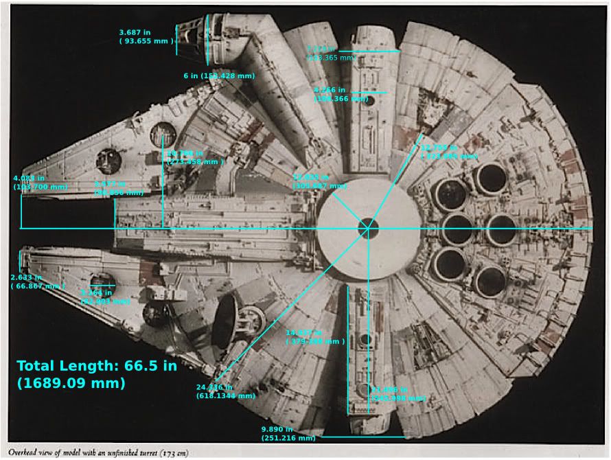
There is still no better picture for scaling than the Chronicles top view, IMO. Add up the pontoon bridge and Chevy parts and you get about 16.59"; scale that to the top view and you get 68" total. (Could even be more if there's extra plastic real estate after the pontoon bridge part.)
The model's present-day display case is about 80" long, FYI.
NP, Stu. And yeah, agreed - it's the best PHOTO for scaling, I didn't mean to suggest it's the best METHOD. Really the best you can do with a photo is approximation; there are differential errors across the whole thing - circles aren't circular, straight lines aren't straight, anything that is more than an inch or two nearer or further from the camera than the centreline is enlarged or shrunken, etc.
I'll greatly look forward to your results. I'm doing likewise, but it'll be tons sketchier than Rodmart's or yours, I expect. Trying to draw up a dimensioned blueprint mostly from photos is DOING MY HEAD IN. Bloody parallax! I need more kit parts, fortunately they are on the way.
Bit of clarification: you were half right about the 'rule' sets - this isn't one of the formal sets shot against black with a metal rule clamped to a c-stand. Rather, the ship is shot in the modelshop without a background (other than the usual clutter) and with Steve Gawley or someone (I forget) just holding the rule. The reason I say the rule wasn't held in the right places is that you could actually see this in some of the shots. To my mind this means its location is questionable in ALL of them, thus it has no value.
There are very few blueprints I've ever come across that I trust and yeah, that goes for mine too, heh. Unless you a) have access to an original model, b) can take a very comprehensive set of measurements and c) really know what you are doing when you take them, then there's always going to be room for improvement. And even with all the reference in the world, you can still make mistakes of interpretation, like the inset detail cutouts below the cockpit windows on the Aliens version of the Narcissus: those were just conduit greeblies on the original. For example re c), one of the published length figures for the Executor only makes sense if it is the figure for a tape line held along the edge trench...and then continued up from the wingtip to the extreme stern, cutting the corner so to speak. Not exactly your traditional surveying technique! There are some things on e.g. the Executor, the Nostromo and the Narcissus that AFAIK nobody has spotted. And I'm talking about hull form issues here, hard to spot ones perhaps but not exactly minor greeblie stuff. If you really want to nail something, the drawing gig isn't as easy as a lot of people think. :lol
God, I haven't paypaled you for the vents. My mum's rejected treatment and may not have long...also doing my head in.

Finally taking shape.
http://pic100.picturetrail.com/VOL589/2452812/4851091/395810364.jpg
Still reworking the mandibles and need to finish adding armor plating on the cockpit tube and the cone itself. I'm, most likely, going to make the mandibles removable with prong type connectors for easier relocating(upstairs in my office or anywhere else). Install the pods.
After that...the hull will be completed! YAY!
http://pic100.picturetrail.com/VOL589/2452812/4851091/395810362.jpg
")