Started this kit at the end of June and am far enough to post my progress.
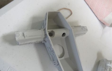
Going from other builds of this kit, it is recommended to brace the head and neck with plywood. Used 5 min epoxie to glue this part together and then bolted it down.
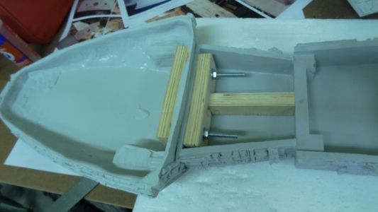
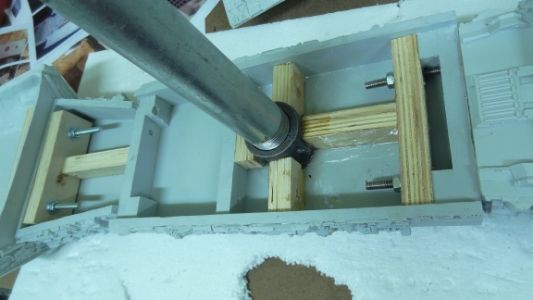
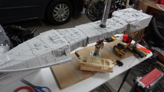
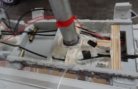
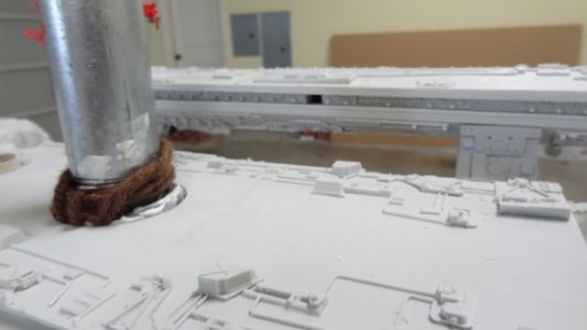
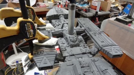
Next up was to install a center mount. Don't know how heavy this thing will be once finished so I went with a 1 inch pipe. Also bolted the engine block to the body same method as the neck.
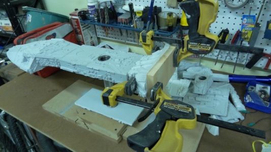
There's a plate that needs to be glued before the engine block can be assembled. 5 min epoxied and used a piece of wood clamped down to keep everything flush.
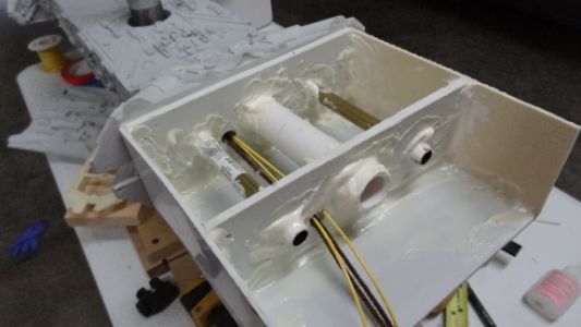
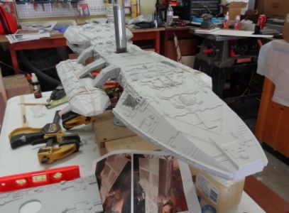
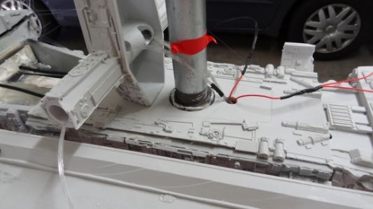
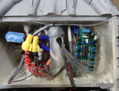
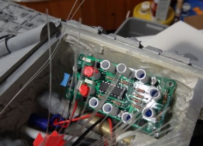
Here's the engine block starting to come together. I smeared resin on all the joints for extra strength. This is where all the LEDs, chaser, and battery will hide. The holes here are for the fiber optics and wires going to the main body and hangers.
So here she is with the 1 inch pipe on the bottom and one on top. I just flip her over and thread the pipe into the flange when I need to work on the bottom side. I just remove the top pipe and cover the hole with a detail piece when I'm complete.
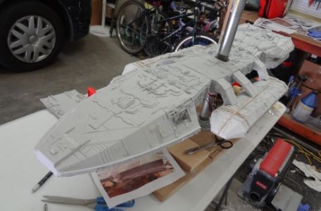
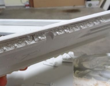
Here the top part of the hanger bays are epoxied in place with 2 inch screw drilled for extra support. The bottom part and front caps of the hanger bays are just rubber banded in place to see if everything looks OK.
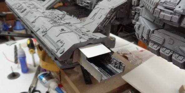
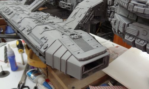
So here we go with the rear hanger bay entrance.
I started by drilling large holes from the front all the way thru to the back.
Now I start removing resin from the back side.
Here it is from the front and with the cap on.
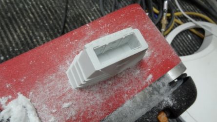
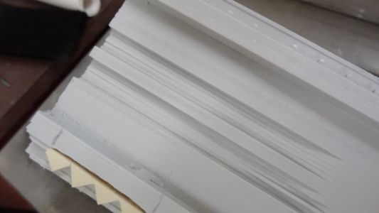
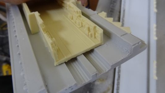
More upgrade parts from RC's landing bay kit. Here are the lower halves of the landing bays and the top one has the existing detail part removed.
And now with the replacement part...
The entrance to the bays will have fiber optics lit with a Blue LED Chaser kit. So here I've marked where the FO will go.
Adjusted the height of my table saw and ran this part thru to get these grooves. This will give me the room underneath to run the fiber optics.
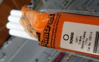
Picked up some fiber optics from http://thefiberopticstore.com/purchase/endglowcable.htm
and went with several of the 0.5mm, 5 ft (64 strands) and 2.5 ft strands. The 5 ft strands will run from the engine to the head. The 2.5 strands will be for the body and hangers. The battery, LED, and switch will be in the engine block so I will run the FO the length of the ship and the jacket keeps all the fibers together.
I just split the jacket open with a hobby knife to release the fibers.
I smear 5 min epoxie to secure all fibers. Don't want them slipping or moving around after the head is glued together.
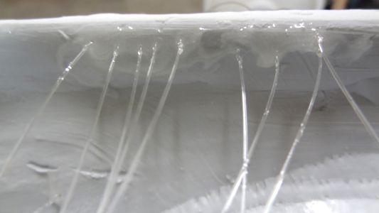
And here it is just before I glue the head together.
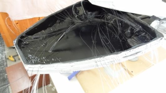
Here's the body before I close it up. You have to finish the body and glue the "coffin" part down before you can glue the top part of the hanger bays.
Here's the coffin part with the arms hollowed out for the fiber optics.
Cut out a small part on the bottom part of the hangers for the fiber optics to pass thru.
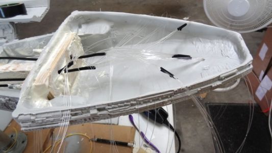
Pushing the wires thru and making sure everything is OK before I start to glue things down.
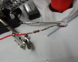
Small update as I put together my LEDs for all the fiber optics. I have 5 of the bundled fiber optics so I am putting together 5 LEDs. Here I'm soldering a negative wire and a resistor with the positive wire. Slipping on some heat shrink tubing and I'm done.
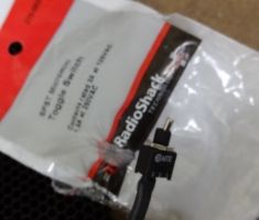
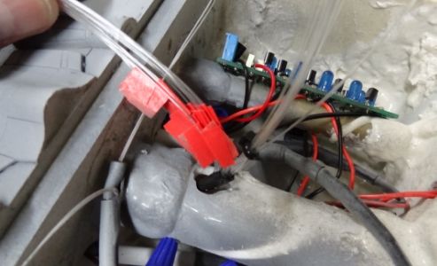
Found this micro on/off switch and will install it on the bottom part of the engine. I shorten the length of the switch by cutting it in half with a dremel.
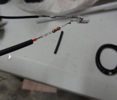
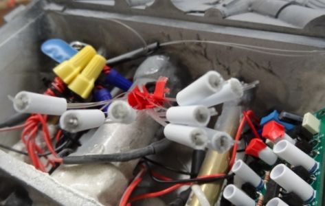
This 1/4 tubing slips over the 5mm LEDs pretty snug, but I added heat shrink tubing to make sure it doesn't slip off.
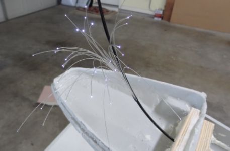
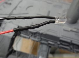
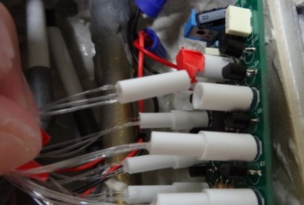
And here's the LED test. The fiber optic bundle just slips into the other end of the styrene tube and pushed all the way in until it touches the LED (did not use heat shrink tubing on the fiber optic side as the heat may melt the fibers).
So I've got one bundle of fibers for the Blue LED chaser and I divide it in half with 16 strands going to both hanger bays.
I just used a small LED flashlight so I can sort out which fibers are going to the right and left hanger bays and I tagged one side with red tape.
Using the styrene tubing again this time for the 8 Blue LEDs. The chaser has 10 LEDs so I taped off the two that I will not be using.
Now I grabbed two fibers from the left and two from the right and encased it in a smaller styrene tubing with aves apoxie sculpt. In the end, there will be 8 smaller styrene tubes with 4 fibers in each.
I trimmed off the excess fibers and slipped them onto the styrene tubing holding the LEDs after the apoxie sculpt had hardened.
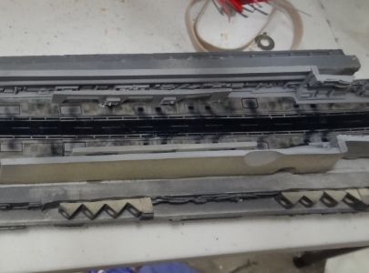
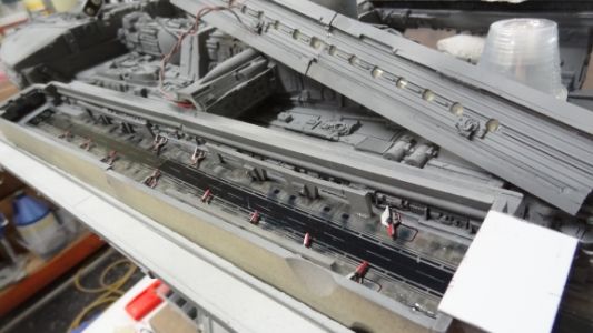
Finishing up the interior of the hanger before I can close up the two halves.
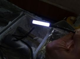
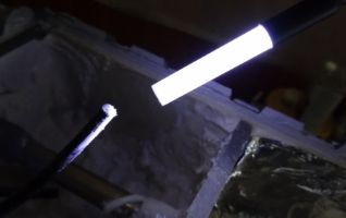
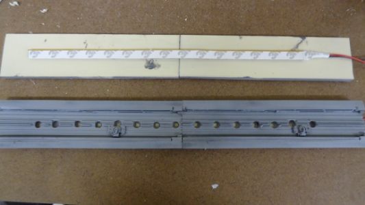
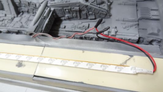
Here are the top of the interior hanger from Randy Cooper's kit. Using a LED strip, marked, and drilled holes for the lights to shine through.
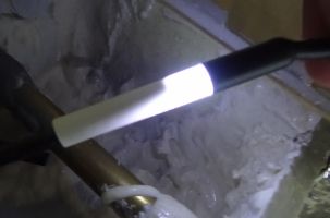
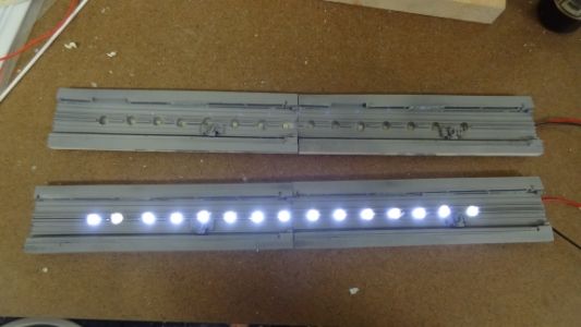
Testing the LEDs with a 9v battery.
The interior is painted, false walls are up, and floor decals applied.
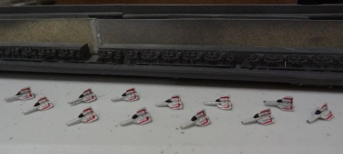
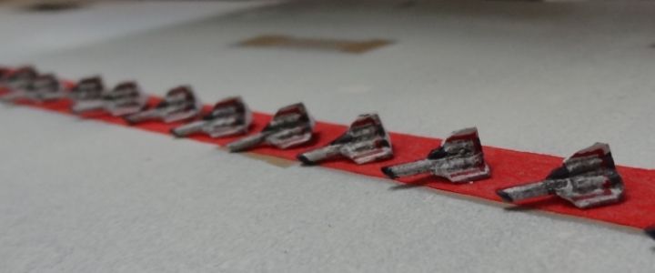
And now onto the tiny vipers. Primed, painted, and weathered...
Here the FO for the landing lights are in place. Remember there were 4 fiber optic strands (2 from the right and 2 from the left hangers) encased in epoxie sculpt going into each blue LED chaser. I start the chaser and slowed down the sequence to help me find which two fiber optic strands light up first and put it the holes closest to the entrance. Continue until I have all 8 pairs in order and then glued down with 5 min epoxie.
Testing the landing lights before I glue the two landing bay halves together.
So here I am closing up the hanger. Randy Cooper's hanger is upside down at this point. Just remember the Galactica is upside down so the entire assembly will need to be flipped over before you close it up.
And now the two halves glued down with 5 min epoxie glue. The entrance cap is not glued down yet. It's just there to make sure Randy Cooper's hanger is the right distance.
Now I can glue on the two front hanger caps.
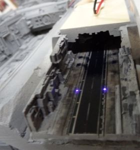
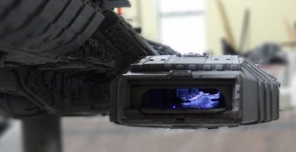
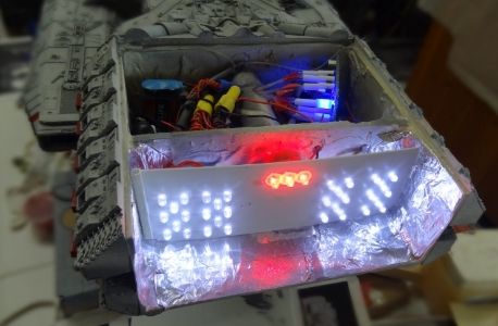
And finally closing up the hanger entrance
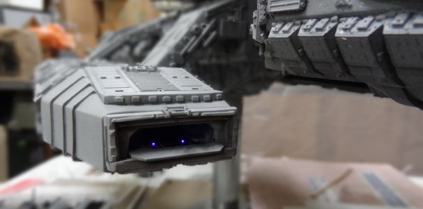
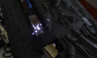
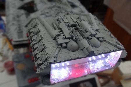
And a shot of the bay lit up!
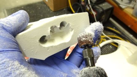
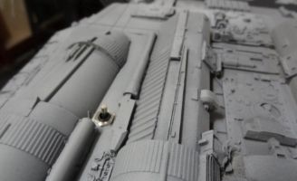
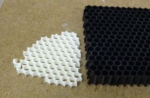
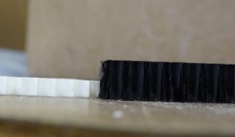
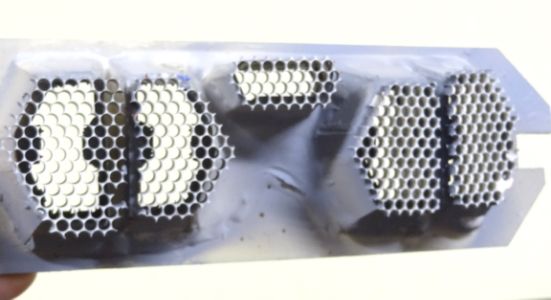
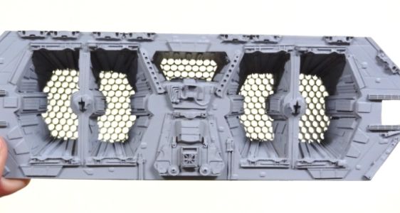
Someone here on the RPF site found this honeycomb grid material for the engines http://www.honeycombgrids.com/grid-catalog/diy-grids I got the 20 degrees light difusion, but when I go to the website now, that option is no longer there. The grid looks great but is a bit tall and sanding it down did not work.
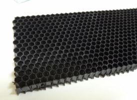
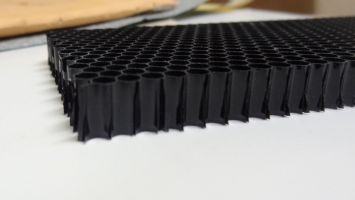
Ended up making a quick mold and cast a copy. I was only able to cast the grid in small sections and demolding it destroyed the mold so it was a one time shot. Was lucky enough to get enough pieces to cover the engines. Here's a pic of the resin copy sanded down.
Here's the pieces glued to the back of the engine and a shot from the front.
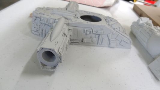
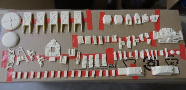
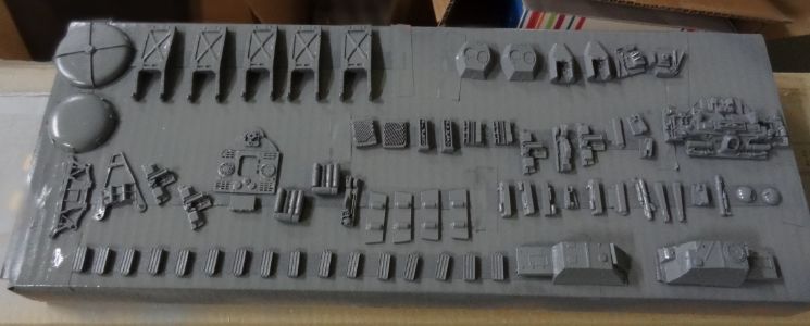
Here I used double sided tape to secure the detail parts for priming. Now gotta figure out where they all go on the ship.
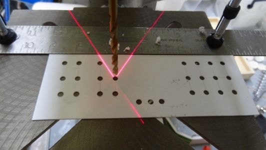
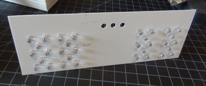
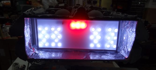
To light the engines, I am drilling holes for 5mm LEDs into a styrene sheet. Eight 5mm white LEDs for each engine and three 5mm reds for the center that are all going to a 9v battery.
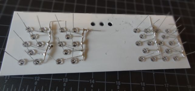
Here I am connecting the LEDs in parallel soldering all the negative leads together first.
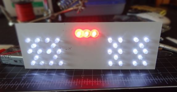
A quick light test to see if there are any loose connections.
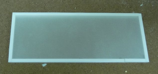
The LEDs are giving some hot spots so I needed to diffuse the light a bit. Here I glued styrene strips together to fit the engine light box. I then cut and glued a transparent piece of paper I got at Michaels.
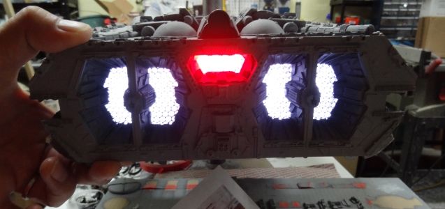
The LEDs are installed, engine top placed down, and diffuser in place. I also put down some reflective tape around the engine.
With lights on and cover in place. Now it's onto all the greeblies and final paint.
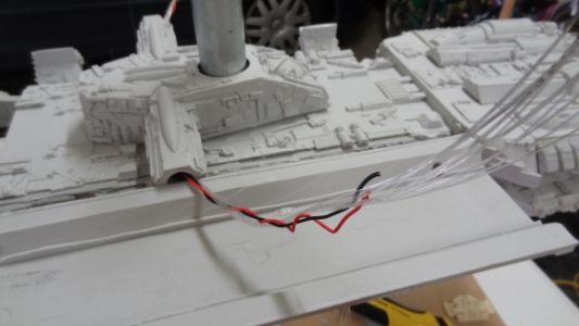
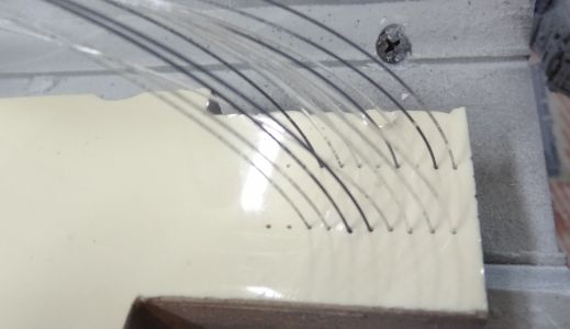
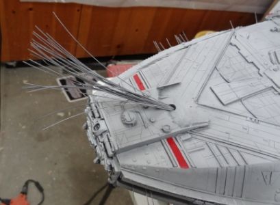
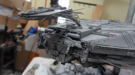
Painting all the red parts took longer than I had planned. Here I am installing the bridge and drilled 25 holes for the fibers.
Threading the fiber optics and securing them on the backside with 5 min epoxie.
The bridge glued down and started to tone down the red areas with some drybrushing.
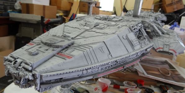
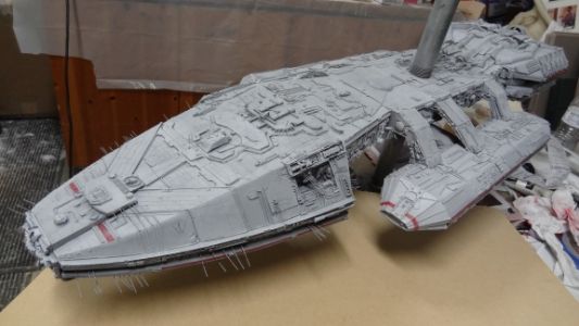
Thanks for following this 3 month journey and hope to have final pics up soon!
Going from other builds of this kit, it is recommended to brace the head and neck with plywood. Used 5 min epoxie to glue this part together and then bolted it down.

Next up was to install a center mount. Don't know how heavy this thing will be once finished so I went with a 1 inch pipe. Also bolted the engine block to the body same method as the neck.

There's a plate that needs to be glued before the engine block can be assembled. 5 min epoxied and used a piece of wood clamped down to keep everything flush.

Here's the engine block starting to come together. I smeared resin on all the joints for extra strength. This is where all the LEDs, chaser, and battery will hide. The holes here are for the fiber optics and wires going to the main body and hangers.

So here she is with the 1 inch pipe on the bottom and one on top. I just flip her over and thread the pipe into the flange when I need to work on the bottom side. I just remove the top pipe and cover the hole with a detail piece when I'm complete.

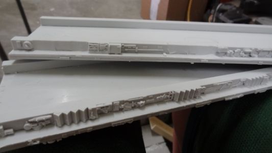
Here the top part of the hanger bays are epoxied in place with 2 inch screw drilled for extra support. The bottom part and front caps of the hanger bays are just rubber banded in place to see if everything looks OK.


So here we go with the rear hanger bay entrance.

I started by drilling large holes from the front all the way thru to the back.

Now I start removing resin from the back side.


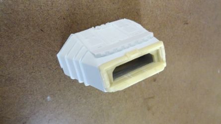
Here it is from the front and with the cap on.


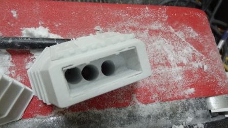
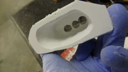
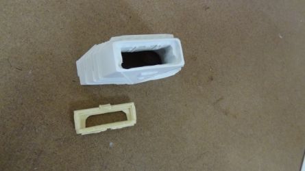
More upgrade parts from RC's landing bay kit. Here are the lower halves of the landing bays and the top one has the existing detail part removed.

And now with the replacement part...

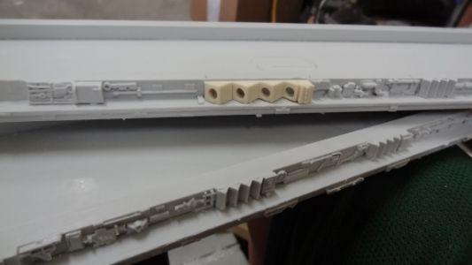
The entrance to the bays will have fiber optics lit with a Blue LED Chaser kit. So here I've marked where the FO will go.

Adjusted the height of my table saw and ran this part thru to get these grooves. This will give me the room underneath to run the fiber optics.


Picked up some fiber optics from http://thefiberopticstore.com/purchase/endglowcable.htm
and went with several of the 0.5mm, 5 ft (64 strands) and 2.5 ft strands. The 5 ft strands will run from the engine to the head. The 2.5 strands will be for the body and hangers. The battery, LED, and switch will be in the engine block so I will run the FO the length of the ship and the jacket keeps all the fibers together.
I just split the jacket open with a hobby knife to release the fibers.


I smear 5 min epoxie to secure all fibers. Don't want them slipping or moving around after the head is glued together.

And here it is just before I glue the head together.

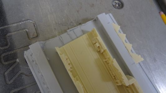
Here's the body before I close it up. You have to finish the body and glue the "coffin" part down before you can glue the top part of the hanger bays.

Here's the coffin part with the arms hollowed out for the fiber optics.


Cut out a small part on the bottom part of the hangers for the fiber optics to pass thru.


Pushing the wires thru and making sure everything is OK before I start to glue things down.


Small update as I put together my LEDs for all the fiber optics. I have 5 of the bundled fiber optics so I am putting together 5 LEDs. Here I'm soldering a negative wire and a resistor with the positive wire. Slipping on some heat shrink tubing and I'm done.


Found this micro on/off switch and will install it on the bottom part of the engine. I shorten the length of the switch by cutting it in half with a dremel.


This 1/4 tubing slips over the 5mm LEDs pretty snug, but I added heat shrink tubing to make sure it doesn't slip off.

And here's the LED test. The fiber optic bundle just slips into the other end of the styrene tube and pushed all the way in until it touches the LED (did not use heat shrink tubing on the fiber optic side as the heat may melt the fibers).


So I've got one bundle of fibers for the Blue LED chaser and I divide it in half with 16 strands going to both hanger bays.

I just used a small LED flashlight so I can sort out which fibers are going to the right and left hanger bays and I tagged one side with red tape.

Using the styrene tubing again this time for the 8 Blue LEDs. The chaser has 10 LEDs so I taped off the two that I will not be using.

Now I grabbed two fibers from the left and two from the right and encased it in a smaller styrene tubing with aves apoxie sculpt. In the end, there will be 8 smaller styrene tubes with 4 fibers in each.

I trimmed off the excess fibers and slipped them onto the styrene tubing holding the LEDs after the apoxie sculpt had hardened.

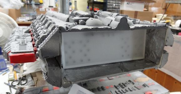
Finishing up the interior of the hanger before I can close up the two halves.
Here are the top of the interior hanger from Randy Cooper's kit. Using a LED strip, marked, and drilled holes for the lights to shine through.

Testing the LEDs with a 9v battery.

The interior is painted, false walls are up, and floor decals applied.

And now onto the tiny vipers. Primed, painted, and weathered...


Here the FO for the landing lights are in place. Remember there were 4 fiber optic strands (2 from the right and 2 from the left hangers) encased in epoxie sculpt going into each blue LED chaser. I start the chaser and slowed down the sequence to help me find which two fiber optic strands light up first and put it the holes closest to the entrance. Continue until I have all 8 pairs in order and then glued down with 5 min epoxie.

Testing the landing lights before I glue the two landing bay halves together.

So here I am closing up the hanger. Randy Cooper's hanger is upside down at this point. Just remember the Galactica is upside down so the entire assembly will need to be flipped over before you close it up.


And now the two halves glued down with 5 min epoxie glue. The entrance cap is not glued down yet. It's just there to make sure Randy Cooper's hanger is the right distance.

Now I can glue on the two front hanger caps.

And finally closing up the hanger entrance


And a shot of the bay lit up!

Someone here on the RPF site found this honeycomb grid material for the engines http://www.honeycombgrids.com/grid-catalog/diy-grids I got the 20 degrees light difusion, but when I go to the website now, that option is no longer there. The grid looks great but is a bit tall and sanding it down did not work.


Ended up making a quick mold and cast a copy. I was only able to cast the grid in small sections and demolding it destroyed the mold so it was a one time shot. Was lucky enough to get enough pieces to cover the engines. Here's a pic of the resin copy sanded down.


Here's the pieces glued to the back of the engine and a shot from the front.


Here I used double sided tape to secure the detail parts for priming. Now gotta figure out where they all go on the ship.


To light the engines, I am drilling holes for 5mm LEDs into a styrene sheet. Eight 5mm white LEDs for each engine and three 5mm reds for the center that are all going to a 9v battery.


Here I am connecting the LEDs in parallel soldering all the negative leads together first.

A quick light test to see if there are any loose connections.

The LEDs are giving some hot spots so I needed to diffuse the light a bit. Here I glued styrene strips together to fit the engine light box. I then cut and glued a transparent piece of paper I got at Michaels.

The LEDs are installed, engine top placed down, and diffuser in place. I also put down some reflective tape around the engine.


With lights on and cover in place. Now it's onto all the greeblies and final paint.


Painting all the red parts took longer than I had planned. Here I am installing the bridge and drilled 25 holes for the fibers.

Threading the fiber optics and securing them on the backside with 5 min epoxie.

The bridge glued down and started to tone down the red areas with some drybrushing.


Thanks for following this 3 month journey and hope to have final pics up soon!
Last edited:


