Someone with a lot of time on their hands could probably make a pair of V2s but with a different color scheme. That would be cool to see.
You are using an out of date browser. It may not display this or other websites correctly.
You should upgrade or use an alternative browser.
You should upgrade or use an alternative browser.
Nike Mag V2 Mod Discussion (Page 58 Shopping List)
- Thread starter Taff83
- Start date
-
- Tags
- back to the future
- Status
- Not open for further replies.
One of the benefits a series connection could give is a progressive power loss indication - IE as the power drops off, so do some of the LEDs. So if the LEDs were wired in series from RED, then YELLOW, then GREEN, the only time the last green LED is lit is at full charge. As the battery goes flat, green LEDs would be the first to go. It would be kind of cool to see that when you have just RED lit your batteries are getting low. The issue is that the LED on the end of the chain starts to dim first.
I don't think it works like that. That understanding presumes that all of the supply voltage goes to the first LED, then what's left over goes to the second in the chain, and so forth, meaning the last LED will dim first as voltage is lost from the power source.
But from my understanding of what happens in a series circuit, the voltage division is equal and instantaneous across all LEDs—they would each get an equal share of the source voltage. If a 9V supply is hooked up to a chain of 9 LEDs wired in series, they each get an equal share, so 1V for a fully charged battery. If they are actually rated for 2V each, getting only half that would underpower them and cause them to be dimmer than their potential. As the battery died and reached 4.5V, then each LED receives .5V each. That said, there are bar graph driver ICs that can be wired to the LEDs to make them light and turn off in sequence as the source voltage changes, essentially becoming a voltmeter circuit.
cavx
Master Member
I don't think it works like that. That understanding presumes that all of the supply voltage goes to the first LED, then what's left over goes to the second in the chain, and so forth, meaning the last LED will dim first as voltage is lost from the power source.
Isn't that what I said? In case my post was not clear, if the series circuit starts at RED then goes to YELLOW and then GREEN, the only time the last green LED is lit is at full charge and it will be the first to dim or even fade out.
But from my understanding of what happens in a series circuit, the voltage division is equal and instantaneous across all LEDs—they would each get an equal share of the source voltage.
That would be a parallel circuit. In series, the first gets most power and all other get proportionally less. If there is voltage overload and the first one blows (and why there is a need for a resister) the whole circuit goes out. In parallel, if one LED dies, all others remain on at equal brightness.
I used a parallel circuit and if one LED was to blow because voltage overload, they all would have blown. They didn't and they all work because the voltage is divided equally over the 12 LEDs.
Series = +-+-
Parallel = ++ and --
Last edited:
cavx
Master Member
I wonder if Taff is one of those grooms who likes taking pictures while wearing his tux and MAGs at the same time. Now that's a look I'd like to see!
Is that a dare for TAFF to wear a pair of MAGs on the big day? I am sure he might like that, but unless his best man and the other grooms men also have the same, the bride may not be happy.
Taff83
Sr Member
Taff, how did you get your 12v LEDs to be so bright? The ones I have are very dim. I've checked and tested and made sure the soldering connections were good enough and I get the same result.
I soldered them like Jedifyfe does. I'm not sure if that would make a difference, but you never know.
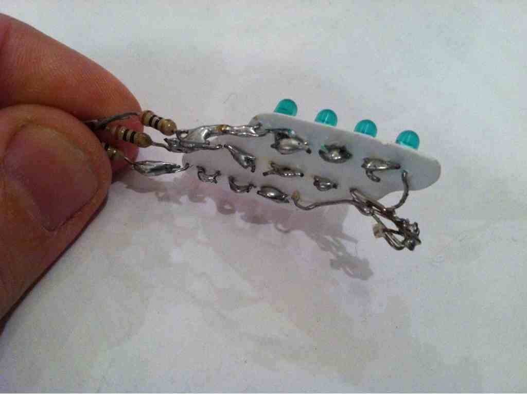
I soldered them parallel as pictured below ( i make my own micro boards using butter lids and copper tape if you want a tutorial just ask and i will post a step by step)
Thanks Robert! ye they are my best pair so farTaff those are terrific!
")
Bang on taff! Been a wile since a pic of a pair has been posted. I do like my pics lol
Like a bus , you wait around for one and you get 2 at once! Lol
A great pair of pairs of mags mate.
Good luck with the wedding! Let's hope our UK weather holds out!
Thanks for the kind words mate and ye fingers crossed i get some nice weather, its in Wales in July so hopefully its all good
Someone with a lot of time on their hands could probably make a pair of V2s but with a different color scheme. That would be cool to see.
I have done a black and red pair see my signature, oh and i'm back working on them so a update soon with them assembled and all the red el glowing in the not to distant future
I wonder if Taff is one of those grooms who likes taking pictures while wearing his tux and MAGs at the same time. Now that's a look I'd like to see!
Is that a dare for TAFF to wear a pair of MAGs on the big day? I am sure he might like that, but unless his best man and the other grooms men also have the same, the bride may not be happy.
Funny you say that, my fiancee actually gave me the green light to wear these for our first dance.. its up to me now to decide if i actually want to wear them.. should i start a poll? highest vote that say yes and i wear them, therpf members decide?
Attachments
Isn't that what I said? In case my post was not clear, if the series circuit starts at RED then goes to YELLOW and then GREEN, the only time the last green LED is lit is at full charge and it will be the first to dim or even fade out.
Yes that's what you said. It's just not what happens. It's actually current (flow of electrons) causing the LEDs to light, and in a series circuit the same amount of available current goes to all connected LEDs in the series chain, meaning that last green LED is getting just as much of this available current as the 1st LED. For it to work the way you think it works you have to hook up a bar graph driver IC chip to create a voltmeter circuit. The voltage is divided between the components, assuming they have similar resistances.
Also, and many people don't realize this, but current flows from negative to positive, meaning the electrons making up the current that will light the chain of LEDs connected in series actually arrives at that last LED FIRST. Since electrons travel at the speed of light, from our observational standpoint the current pretty much is supplied to all connected components instantaneously.
That would be a parallel circuit. In series, the first gets most power and all other get proportionally less. If there is voltage overload and the first one blows (and why there is a need for a resister) the whole circuit goes out. In parallel, if one LED dies, all others remain on at equal brightness.
I used a parallel circuit and if one LED was to blow because voltage overload, they all would have blown. They didn't and they all work because the voltage is divided equally over the 12 LEDs.
Nope. Voltage is not divided in a parallel circuit. In a parallel circuit, they all receive the FULL source voltage because they all have a direct connection to the source voltage. The CURRENT is divided between the LEDs.
Some of what you're saying is correct. One blown LED in a series circuit will cause the other LEDs to go out because the flow of electrons has been interrupted and only one continuous path for the LEDs is available in a series circuit. One blown LED in a parallel circuit will not cause the others to go out, because the others still have a direct connection to the source voltage.
DL4567
Sr Member
I soldered them parallel as pictured below (i make my own micro boards using butter lids and copper tape if you want a tutorial just ask and i will post a step by step)
Alright, I guess that solves the mystery about the 12v LEDs. Wiring them in parallel gives each LED the full 9 volts of the battery. Wiring them in series (which is what I did) runs only 2.25 volts through each LED. Must be why they look dim to me, and also Mitas if he soldered them in series too.
Alright, I guess that solves the mystery about the 12v LEDs. Wiring them in parallel gives each LED the full 9 volts of the battery. Wiring them in series (which is what I did) runs only 2.25 volts through each LED. Must be why they look dim to me, and also Mitas if he soldered them in series too.
I soldered mine positive to negative like this picture. Is this the wrong way to do it with these 12v LEDs? And does the copper tape make a difference?
if you want a tutorial just ask and i will post a step by step)
I'd really appreciate it if you did
Last edited:
There is SO much wiring for these things. It's a bit overwhelming.
Here's what the online program suggested for 3 rows of 3 2.2V LEDs with a 15-20amp rating being powered by a supply voltage of 9V:

This is a COMBINATION series/parallel circuit, where each LED inside a certain row is wired in series with the other two LEDs in that row, and each row of 3 LEDs is wired in parallel with the other two rows.
To explain what you're looking at in the above picture, since each ROW is wired in parallel (attached directly to the source voltage) each ROW is getting the full 9V, and splitting the available current from the 9V battery.
Within each ROW of LEDs that are wired in series, the amount they drop the voltage is added together. 2.2V X 3 = a 6.6V drop within each row, and a small resistor for each row is needed. You could probably do without that resistor and overdrive the LEDs if you're ok with the brighter overdriven LEDs = shorter life LEDs result.
I'm certainly not an electronics engineer so if anyone that has a good solid handle on circuit design sees an error in my explanation of this circuit, please chime in.
Also, a 3.3V system should work fine, but the wiring would be horrendous. Assuming 2.2V LEDs are used, EVERY LED would have to be wired in parallel to receive power directly from the source voltage, like this:

At least, that's what the online program tells me...
This is a COMBINATION series/parallel circuit, where each LED inside a certain row is wired in series with the other two LEDs in that row, and each row of 3 LEDs is wired in parallel with the other two rows.
To explain what you're looking at in the above picture, since each ROW is wired in parallel (attached directly to the source voltage) each ROW is getting the full 9V, and splitting the available current from the 9V battery.
Within each ROW of LEDs that are wired in series, the amount they drop the voltage is added together. 2.2V X 3 = a 6.6V drop within each row, and a small resistor for each row is needed. You could probably do without that resistor and overdrive the LEDs if you're ok with the brighter overdriven LEDs = shorter life LEDs result.
I'm certainly not an electronics engineer so if anyone that has a good solid handle on circuit design sees an error in my explanation of this circuit, please chime in.
Also, a 3.3V system should work fine, but the wiring would be horrendous. Assuming 2.2V LEDs are used, EVERY LED would have to be wired in parallel to receive power directly from the source voltage, like this:
At least, that's what the online program tells me...
Last edited:
ProgramThis
New Member
So my el sheet arrived today going to try the mod tonight.
but i also went to pickup my needlepoint applicator bottle today as i was told it was in i drive 30 mins to get it .. and guess what they couldnt find it made some excuse about amount of days they hold items then the smart ass salesman tells me he sold the last one before i got there and that i should have came earlier... wont be doing buissiness with them again that's for sure
but i also went to pickup my needlepoint applicator bottle today as i was told it was in i drive 30 mins to get it .. and guess what they couldnt find it made some excuse about amount of days they hold items then the smart ass salesman tells me he sold the last one before i got there and that i should have came earlier... wont be doing buissiness with them again that's for sure
How do you lead the metal EL pins to wires to go to the inverter?
Last edited:
ProgramThis
New Member
Never mind figured it out
Last edited:


Don't forget to iron down the lace ribs.
Last edited:
Here are my toe mods and outersole. And yes, it is still clear. My camera just doesn't capture it well.
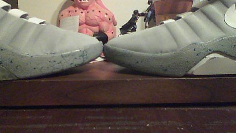
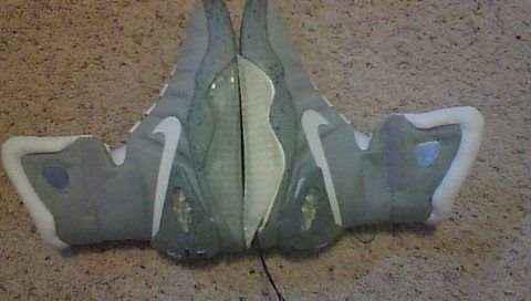
Also it's not as bright in person, but it's a heck of a lot better than what it was. And it's not glued back on yet, but it will be soon.
Question: Has anyone ever thought of dying their soles icy blue like the RDs? Someone with multiple pairs could have a movie version and the 2011 version.
Also it's not as bright in person, but it's a heck of a lot better than what it was. And it's not glued back on yet, but it will be soon.
Question: Has anyone ever thought of dying their soles icy blue like the RDs? Someone with multiple pairs could have a movie version and the 2011 version.
Last edited:
DL4567
Sr Member
As its been said before, you just can't rush art! After some literal blood, sweat, and tears, I've finally completed one shoe in the aqua panels.
View attachment 180128
View attachment 180127
I shoud have the other shoe done either this or next weekend. These will be the pair I keep for me.
Very nice Robert! Did you decide not to reverse the strap?
- Status
- Not open for further replies.
Similar threads
- Replies
- 10
- Views
- 2,876
- Replies
- 5
- Views
- 972
- Replies
- 4
- Views
- 905
- Replies
- 12
- Views
- 1,565