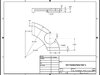
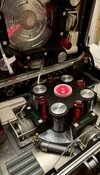
This is what I settled on for the final part, the upper section metal foundation. Rather than 1 large ring, it’s separated into 4 arc pieces. Reels will fit in the gaps. There’s 1 version with the “ledge” for the Clippard and one version without, though I’m not sure I’ll be able to actually fit the cylinders in.
You are using an out of date browser. It may not display this or other websites correctly.
You should upgrade or use an alternative browser.
You should upgrade or use an alternative browser.
Portable Automated Somnacin IntraVenous (PASIV) device, "INCEPTION" *spoliers?*
- Thread starter Chronos
- Start date
Final parts are in! Did some test fitting last night, figured out the order of operations for assembly, and I think I have my plan. I went ahead and attached the Upper Pumps to the Upper Foundation arcs, and permanently installed the rotor disc in the lid as well. Now I just need a few hours set aside to do the build out and I'm calling this done.
Next update will be final, full photos of everything.
Next update will be final, full photos of everything.
Here it is!
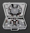
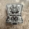
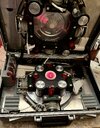
After 18 months, weighing in at 29.2 lbs, and containing 359 separate components (not counting the 152 screws), the Portable Automated Somnacin IntraVenous (PASIV) device from Inception:


Special thanks to Filip Misilo and Futurescape3D for help with the printed parts, Douglas McDunnell and Jordan Perry for help with the CNC machined parts, Feezlenuts for the display plaque, and my wife for the photo shoot and her incredible patience as this sat unfinished on our dining room table for so many months.
After 18 months, weighing in at 29.2 lbs, and containing 359 separate components (not counting the 152 screws), the Portable Automated Somnacin IntraVenous (PASIV) device from Inception:
Special thanks to Filip Misilo and Futurescape3D for help with the printed parts, Douglas McDunnell and Jordan Perry for help with the CNC machined parts, Feezlenuts for the display plaque, and my wife for the photo shoot and her incredible patience as this sat unfinished on our dining room table for so many months.
Here it is!
After 18 months, weighing in at 29.2 lbs, and containing 359 separate components (not counting the 152 screws), the Portable Automated Somnacin IntraVenous (PASIV) device from Inception:
View attachment 1302201
View attachment 1302202
View attachment 1302203
View attachment 1302204
View attachment 1302205
View attachment 1302206
View attachment 1302207
View attachment 1302208
View attachment 1302209
Special thanks to Filip Misilo and Futurescape3D for help with the printed parts, Douglas McDunnell and Jordan Perry for help with the CNC machined parts, Feezlenuts for the display plaque, and my wife for the photo shoot and her incredible patience as this sat unfinished on our dining room table for so many months.
So awesome. Obviously it's no secret to you, but your build has been the biggest inspiration as I work on tackling my own replica. It's been great comparing notes and seeing how you approached each part of the case. Can't wait to finish mine up so I can get it on display.
Van Helmont
New Member
I’ve been looking for this for ten years - this is beyond my capacities as propmaker!
Congratulations on succeeding where many of us, well, didn’t
With all the work involved, I suppose custom work is out of the question ?
Congratulations on succeeding where many of us, well, didn’t
With all the work involved, I suppose custom work is out of the question ?
I’ve been looking for this for ten years - this is beyond my capacities as propmaker!
Congratulations on succeeding where many of us, well, didn’t
With all the work involved, I suppose custom work is out of the question ?
I’m happy to share my parts spreadsheet and some other model info, but I don’t have it in me to make another one. Also cost might be an issue.
Holy smoke! That's awesome!!! Don't know how I miss this! I'm honored to have my tokens next to it!
Longtime thread bump to share these awesome vials I just got in from Prop Fiction Studios. The labels are full of fun little details, like mentioning MV-235A (the model number on the PASIV manual that came with the deluxe BluRay).
I seriously wanted to buy the screen used spinning top from the PropStore.com auction last week, but it ended up fetching over $31,000.
I seriously wanted to buy the screen used spinning top from the PropStore.com auction last week, but it ended up fetching over $31,000.
Attachments

I’m working with a company to produce a custom enamel pin of the PASIV and wondered if anyone here would like to get one? Cost would be $15 shipped each inside the US. Shipping overseas cost TBD.
It’s about 1.5” tall and will be a soft epoxy enamel with a dome coat.
It’s about 1.5” tall and will be a soft epoxy enamel with a dome coat.
Attachments
Update!
I've decided to finally work on adding FX to the case. There are a few tiers of feasibility here, and I'll start with the simplest and work my way up.
Tier 1: Basic Light & Sound
At a minimum, I would like to install a center activation button under the silicon button boot that acts as a pushbutton to start the machine. That essentially just means playing a looped sound effect of the machine's pumps and bellows moving air and Somnacin compound around. There are 2 audio files, one that is a long hiss that will play at startup, and then a more involved sequence of compression/pumping/decompression sounds that loop after that until the activation button is disengaged. The sound effect is mostly taken from a movie scene, cleaned up, and then a little bit of a low pitched hum added for presence. There wil lbe a master power switch, likely hidden under one of the small door flaps.
Tier 2: Fake Timers
I'd like *something* on the Timer displays. I've seen 2 versions of this prop, one with green LCD displays, and one with black LED displays. In the movie, all we see are black LED displays with a red dot matrix readout of the remaining time on the clock. This is the look I'd like to replicate. I have spent an insanely long amount of time trying to find displays of this type at this size, and I've concluded they probably just don't exist, or are so rare or custom they are unattainable. Even so, I'm not sure the required electronics would even fit inside the remaining space in my timer housings. So my second choice is to fake it. I'm going to look into replacing my green "LCD" acrylic panels with black acrylic with laser cutout dots for the "time", with rear red illumination to fake a real dot matrix display. They'll be static, but at least it's something.
Tier 3: Real Timers
If some day in the future I am able to work it out, putting real timers and displays in the housing, adjustable by the 2 white buttons on each side. Today, those buttons are just dummies and not conneced to anything).
Tier 4: Motorized Cable Spools
I am extremely skeptical of this every becoming possible, but why not list it? The dream is to install real step motors that drive the tiny gears and belts and able to automatically wind the IV tubing back up onto the spools. Today, I can freely pull the tubing out as long as I need, but then I have to manually wind it back up. So far, the tiniest motors I could find are still far too large to fit where they would need to go.
I start with Tier 1 last night, getting the correct illuminated pushbutton and power source working. I have a sound board on the way, and I'll need to print up a mount for the button so it can be positioned precisely where I need it directly under the silicon cover.
This is amazing. I can’t wait to see the results. I personally would love to just get light and sound in mine at some point.Update!
I've decided to finally work on adding FX to the case. There are a few tiers of feasibility here, and I'll start with the simplest and work my way up.
Tier 1: Basic Light & Sound
At a minimum, I would like to install a center activation button under the silicon button boot that acts as a pushbutton to start the machine. That essentially just means playing a looped sound effect of the machine's pumps and bellows moving air and Somnacin compound around. There are 2 audio files, one that is a long hiss that will play at startup, and then a more involved sequence of compression/pumping/decompression sounds that loop after that until the activation button is disengaged. The sound effect is mostly taken from a movie scene, cleaned up, and then a little bit of a low pitched hum added for presence. There wil lbe a master power switch, likely hidden under one of the small door flaps.
Tier 2: Fake Timers
I'd like *something* on the Timer displays. I've seen 2 versions of this prop, one with green LCD displays, and one with black LED displays. In the movie, all we see are black LED displays with a red dot matrix readout of the remaining time on the clock. This is the look I'd like to replicate. I have spent an insanely long amount of time trying to find displays of this type at this size, and I've concluded they probably just don't exist, or are so rare or custom they are unattainable. Even so, I'm not sure the required electronics would even fit inside the remaining space in my timer housings. So my second choice is to fake it. I'm going to look into replacing my green "LCD" acrylic panels with black acrylic with laser cutout dots for the "time", with rear red illumination to fake a real dot matrix display. They'll be static, but at least it's something.
Tier 3: Real Timers
If some day in the future I am able to work it out, putting real timers and displays in the housing, adjustable by the 2 white buttons on each side. Today, those buttons are just dummies and not conneced to anything).
Tier 4: Motorized Cable Spools
I am extremely skeptical of this every becoming possible, but why not list it? The dream is to install real step motors that drive the tiny gears and belts and able to automatically wind the IV tubing back up onto the spools. Today, I can freely pull the tubing out as long as I need, but then I have to manually wind it back up. So far, the tiniest motors I could find are still far too large to fit where they would need to go.
I start with Tier 1 last night, getting the correct illuminated pushbutton and power source working. I have a sound board on the way, and I'll need to print up a mount for the button so it can be positioned precisely where I need it directly under the silicon cover.
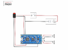
Here are some of the components I've selected:
Sound Board:

 www.adafruit.com
Red Illuminated Activation Switch:
 www.adafruit.com
Speakers:
Master Power Switch:
(Only using the toggle, the white housing is too large to fit where I want it)
Battery Case:
(Just using 2 regular Eneloop AA's for power)
So far I have the electronic components all wired up and connected and it ~mostly~ works. The master power turns on power to both the sound board and the LED activation trigger, so as long as power is on, the red light is active. This is the activation button that goes in the center of the case under the silicon cover. I will need to build a mount (probably printed) that goes under the lower pump housing and brings the trigger button all the way up to right under the silicon cover. At this stage, after master power is on, the trigger does indeed start playing the sound through both speakers on a loop as long as the button is latched into the On position. I plan to conceal the Master Power Switch underneath one of the hinged door flaps. Everything is wired up with quick connectors between components to make installation and maintenance much easier. Huge shout-out to these heat shrink connectors with built-in solder. I am never going to manually solder wire to wire again: Amazon.com
The problem I have is that the Adafruit board by default seems to have a fairly low volume, and while there are trigger pins for raising volume, there's no memory for it, so it has to be raised every time it's powered on. I could use my activation trigger to simultaneously send a signal to the Volume+ pin but I could only increment it by 1 step, which isn't much. I could wire up separate volume buttons some where in the case, but they'd need to be pressed every time I turned it on, which is inelegant and kind of ruins the prop's immersion.
I've also tried using ffmpeg to raise the dB of the WAV file I'm using for the effect, but I can't raise it much without introducing clipping artifacts, which the sound board very much does not like. Anything but a perfectly pristine file appears to trip up the board and make it prematurely restart the loop, not to mention the ugly sound of the clipping.
So I'm experimenting with a few things to try to get the sound a bit louder. I still haven't actually tried the wiring setup inside the PASIV yet, which honestly may naturally amplify it due to the speakrs being placed right under the metal base plates.
Sound Board:
Adafruit Audio FX Sound Board + 2x2W Amp - WAV/OGG Trigger -16MB
Would you like to add audio/sound effects to your next project, without an Arduino+Shield? Or maybe you don't even know how to use microcontrollers, you just want to make a sound play ...
www.adafruit.com
Red Illuminated Activation Switch:
16mm Illuminated Pushbutton - Red Latching On/Off Switch
A switch is a switch, and an LED is an LED, but this LED illuminated button is a lovely combination of both! It's a medium sized button, large enough to press easily but not too big that ...
www.adafruit.com
Speakers:
Master Power Switch:
(Only using the toggle, the white housing is too large to fit where I want it)
Battery Case:
(Just using 2 regular Eneloop AA's for power)
So far I have the electronic components all wired up and connected and it ~mostly~ works. The master power turns on power to both the sound board and the LED activation trigger, so as long as power is on, the red light is active. This is the activation button that goes in the center of the case under the silicon cover. I will need to build a mount (probably printed) that goes under the lower pump housing and brings the trigger button all the way up to right under the silicon cover. At this stage, after master power is on, the trigger does indeed start playing the sound through both speakers on a loop as long as the button is latched into the On position. I plan to conceal the Master Power Switch underneath one of the hinged door flaps. Everything is wired up with quick connectors between components to make installation and maintenance much easier. Huge shout-out to these heat shrink connectors with built-in solder. I am never going to manually solder wire to wire again: Amazon.com
The problem I have is that the Adafruit board by default seems to have a fairly low volume, and while there are trigger pins for raising volume, there's no memory for it, so it has to be raised every time it's powered on. I could use my activation trigger to simultaneously send a signal to the Volume+ pin but I could only increment it by 1 step, which isn't much. I could wire up separate volume buttons some where in the case, but they'd need to be pressed every time I turned it on, which is inelegant and kind of ruins the prop's immersion.
I've also tried using ffmpeg to raise the dB of the WAV file I'm using for the effect, but I can't raise it much without introducing clipping artifacts, which the sound board very much does not like. Anything but a perfectly pristine file appears to trip up the board and make it prematurely restart the loop, not to mention the ugly sound of the clipping.
So I'm experimenting with a few things to try to get the sound a bit louder. I still haven't actually tried the wiring setup inside the PASIV yet, which honestly may naturally amplify it due to the speakrs being placed right under the metal base plates.
Got my audio file issues worked out. It needed to be a 22kHz 16-bit mono WAV. I decided against separating the startup sound and the loop and just have the startup hiss looping with the main sound every 1:05.
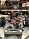
I got quite a bit done this weekend, installed the master power switch, figured out where everything will go, and installed a holder mount for the activation trigger. I still need to step down the voltage a bit so I don’t burn out my LED prematurely, but things are promising.
I got quite a bit done this weekend, installed the master power switch, figured out where everything will go, and installed a holder mount for the activation trigger. I still need to step down the voltage a bit so I don’t burn out my LED prematurely, but things are promising.
Attachments
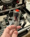
I used a small bead of Pro Poxy 20 steel reinforced putty to hold the master power switch in place behind the lower trap door, and noticed the plastic tube the epoxy comes in would work perfectly for the activation button mount. A little modification later, it works perfectly.
Attachments

I'm waiting on a couple of resistors and an extra speaker to arrive before I call it good on Tier 1. Meanwhile, I'm working on the timer design for Tier 2 FX.
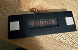
The first thing I'll need to do is remove the green "LCD" screens from my Timers and replace them with black "LED" panels. This means coming up with a design for the countdown timers. I'm using this screen grab for reference:

Rather than recreate it from scratch, I found a font (sort of) that is almost exactly it. It's the right number of dots at least, in the right positions. Unfortunately I can't find it as an actual font file, but rather a screenshot of all the characters, so it took some manual copy & pasting to come up with this.
I probably won't use 00:00:00 for all 8 timers, but I'm still brainstorming on what to put on some of them. These will be faux and static, after all, and should probably be a little more interesting.
The first thing I'll need to do is remove the green "LCD" screens from my Timers and replace them with black "LED" panels. This means coming up with a design for the countdown timers. I'm using this screen grab for reference:
Rather than recreate it from scratch, I found a font (sort of) that is almost exactly it. It's the right number of dots at least, in the right positions. Unfortunately I can't find it as an actual font file, but rather a screenshot of all the characters, so it took some manual copy & pasting to come up with this.
I probably won't use 00:00:00 for all 8 timers, but I'm still brainstorming on what to put on some of them. These will be faux and static, after all, and should probably be a little more interesting.
Attachments

Even just a printed mockup on paper is pretty convincing. The trouble I'm going to have is finding who can laser cut acrylic this small. The visible area on the top of the timer is around 32mm x 8mm, so the digits have be even smaller than that. And so far the smallest holes I've found anyone can cut are 1.2mm. My cheap inkjet struggles to print dots that tiny and well-defined.
Attachments
Similar threads
- Replies
- 12
- Views
- 1,561
- Replies
- 17
- Views
- 1,553
- Replies
- 23
- Views
- 3,011
- Replies
- 8
- Views
- 2,029