New thoughts on the Obi ANH 'Reflector'

I agree, when I jumped on board and decided to purchase the parts separately over time I just assumed that they would be made so that I could put each piece together easily. I got the emitter and transistors already and paid for the grenade, I really like the quality and appreciate the hard work that is going into these pieces but im a little worried that putting the complete saber parts together might be more difficult then I thought. I agree with those who want the most accurate parts I do to, but I think the inner connections can be made by the machinist so that we get the best reproduction of this saber possible and not sacrifice accuracy on any visible areas.
Here is how I see it the saber is a replica in every way, but the great thing about having one custom made like this is that you get the awesome appearance of the original lightsaber without all the flaws of trying to get the parts to stay together tightly. I am still new here and I don’t want anyone to think im talking bad about your work on this project. I want the parts ether way this is just my opinion on the matter. Thanks


With the exception of the emitter/grenade transition piece that is still being discussed there isn't any part of this saber that does not fit together very easily with all original parts (or perfect and exact replicas of such) I've assembled many of these, they just need a threaded rod and everything stays together just fine being pressure fit together.

I think we are getting people jumping on the designers that have yet to even attempt to assemble the parts...it's seriously a lot of unnecessary worrying, I don't have a big machine shop or tool bench of fancy tools and I've been able to put these together just fine.

My .02
 
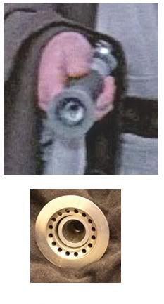
I see a taper from the large front hole down to the small hole at the back.
I don't see a flat wall at the back with the small hole in the middle, or an indication of any other surface back there with the hole in the middle.

Emitterfromfront2.jpg


Dewy, we can't win, can't please everyone.
Some want 100% accurate parts and that's it. They're quite happy to walk away and tinker the saber together how they see fit.
Others want 100% accuracy, but at the same time want putting the saber together made as easy as possible. I can understand both points of view.
So, originally the idea was to produce the parts and have done with it.
But, then there's this senario.
'Hey, how do I connect this emitter thing to the grenade - there's a frikkin huge gap?'
'Sorry bud, you got what you paid for, figure it out yourself.'
We didn't adopt that position, hence the 'cone' adaptor I've been working on over the past few months or so, and the clamp spacer I mentioned earlier that I'm working on which will secure the booster and the grenade inside the clamp.
The emitter is the most accurate to the prop yet. Nothing was altered to aid construction.
The grenade will be the most accurate to the prop yet. Yes, we spoke about 'unseen' differences to aid construction regards the 'cone' adaptor, but there we're a few who were unhappy with, for whatever reason, knowing there was something there they couldn't see being different from what they couldn't see in the first place, I think. :confused

The threading at the base of the frag body, a case in point. It's not going to be seen, so why include it? It's an extra set up, extra work for all concerned, takes more time, so why bother?
No worries, the threading's there.
The overall plan regards construction is a tight fit by the use of machining tolerances and a little JB Weld here and there.
When all the parts are on my bench, I'll post a little step by step, but to be honest I don't think they'll be many guys who'll need it.
 
Sith_Lord_Hritz:

Ease of assembly is still a goal here, that has NOT been dropped.

But be aware that at the grenade/emitter junction you cannot have these three things at the same time:

1. Individual part accuracy
2. Perfect assembled prop accuracy
3. Ease of assembly

People keep posting their wishes as though perfection in these three things is possible simultaneously at the grenade/emitter junction and it simply isn't. Period. :)

The design for the connection which Howard is currently planning to offer allows individual part accuracy and ease of assembly with a very slight compromise with regard to the size and position of the small hole deep inside the emitter.

For people who are satisfied with the appearance which would result from threaded rod construction, this part (which does not attach to a threaded rod) will certainly satisfy as far as accuracy, and it will be about as easy. Those who want to follow my ideas on the small hole (and I gather not many do) will have the option of putting the accurate parts together however they see fit (and I will post something about this after the grenades are delivered).
 
Last edited:
Thanks Scott. :thumbsup

EDIT:
Thanks Andres. :thumbsup

The threaded rod is tried and tested, but at the emitter end can be dammed ugly, so I didn't want to go down that route at all.
It'll all work, I'm sure of it.
I will post a tutorial once I have all the parts on my bench.
As for tools?
2 part epoxy and a few toothpics.

EDIT: Just wanted to say that that tool remark I made wasn't directed at you, Scott - all I have his a few files, pliers, a mini vice and glue myself.
I'm just trying to point out construction should be within everyone's grasp.
 
Last edited:
So close to the end......I can taste it!!! :) Thanks guys for making such an effort on our behalf. You've done a fantastic job on this. Everyone will agree once they get them in hand.

Dave
 
I have an idea for a clamp spacer. This design (still on the drawing board) will overcome the problem of securing the grenade to the clamp's front end and the booster to the rear. The design will no affect the integrity of either the booster or the grenade as accurate reproductions, and will also allow the transistors to be fitted before the spacer is applied.

So let me make sure here. You're saying it's perfectly safe for me to attach my transistors to my Graflex clamp, and apply jd's decals so everything is alligned correctly right now, and not have to worry about insertion of the future spacer being a problem? Right?
 
TridCloudwalker I'd hold off till you have all the parts ready and waiting. It will be worth it!
MANY THANKS to all involved for making this cone. It will ROCK! I was just wondering about the small hole at the back and if it would be threaded. No worries. JB weld will work if there isn't any. The threaded rod technique worked for me and I think everyone will have great, and easy success with it too! (y)thumbsup
 
Last edited by a moderator:
This is all well and good but will it actually create a blade of pure destructive energy when assembled. Will the color of the blade be screen accurate?
 
We almost had it worked out, but to get the full blade width with the blue color we had to reduce the power slightly so you had to kind of saw the blade back and forth to cut through things. We could get the full power by either having a slight green tint to the color or by having a slightly narrower blade but people kept complaining so we scrapped the blade. :D


:)lol)
 
dammit
We almost had it worked out, but to get the full blade width with the blue color we had to reduce the power slightly so you had to kind of saw the blade back and forth to cut through things. We could get the full power by either having a slight green tint to the color or by having a slightly narrower blade but people kept complaining so we scrapped the blade. :D


:)lol)

Damn, you beat me to it!
:lol:lol:lol
 
Thanks Andres!

I was thinking of doing something like this:
DarthLars-Obi-Wanemittersketch1.jpg

Put it together with an expanding rubber washer like ATL Kenobi did. The red part would have to be machined. Not perfected yet.
 
DL very thought-provoking. I like the idea for how the red piece works and will mull over some other ways to approach the rest. Thank you!
 
I stumbled upon this on eBay today (not a live auction) and it reminded me of something...
http://cgi.ebay.com/ws/eBayISAPI.dll?ViewItem&item=330303386576

3775_1.jpg
38e3_1.jpg


Main body seems a little tall and the opening seems a little big, but it's the correct size overall.
Could we actually be looking for something like this?

Auction description:
>>>
Here is a newly made fragmentation adapter for a World War Two era M17 Impact Fuzed Rifle Grenade. If you have a spare fin stabilized fuzed tube for either an M9A1, M19A1, M22, M23 you can screw this adapter onto your tube, attach a MKII frag body onto the front and have yourself a super-rare M17 for your display collection. An economical solution to add a highly sought after, expensive and super-rare M17 rifle grenade to your US ordnance collection.
This newly made adapter is precisely machined and threaded on a lathe. The exact dimensions were taken from an original, World War Two era M17 adapter. The outside diameter is .938 which is the average diameter of original fuzed rifle grenade tubes. It is spray painted with a semi-gloss olive drab and can be repainted by you if you need to match your existing tube's color. The internal threads are 3/4"-16 TPI and the front threads are 9/16"-12TPI. These are the same thread sizes for a fuzed tube and a original frag grenade body.
For those of you who do not know what the M17 was, I have included in the description a picture of an original M17 taken from one of the inert ordnance websites that shows how an M17 is supposed to look. Further information can be found at EJ's Inert Ord website:
http://www.inert-ord.net/usa03a/usarg/rg/index.html
<<<
 
Last edited by a moderator:
I'm inclined to think not, just because the hole at the bottom of the hole in the 'thing' inside the emitter seems to be about the size of the hole at the top of the grenade neck.

So although this piece relates to a practical solution for assembly purposes, I doubt we'd find an original part with the tapers and thin walls necessary to create the appearance of that hole size while using a threaded extension. (Just for clarity's sake, no one should take the latter comments as describing anything to do with the upcoming run of attachment pieces, which I did not design FWIW.)
 
This thread is more than 15 years old.

Your message may be considered spam for the following reasons:

  1. This thread hasn't been active in some time. A new post in this thread might not contribute constructively to this discussion after so long.
If you wish to reply despite these issues, check the box below before replying.
Be aware that malicious compliance may result in more severe penalties.
Back
Top