...now when I said I was going to 'hack' the crap out of this SureElectronics module, I meant that
literally.
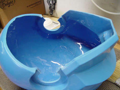
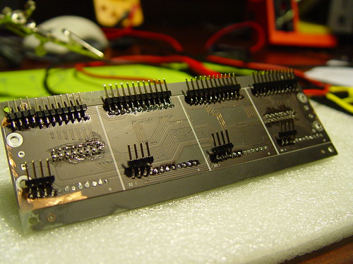
So, here's the module intact
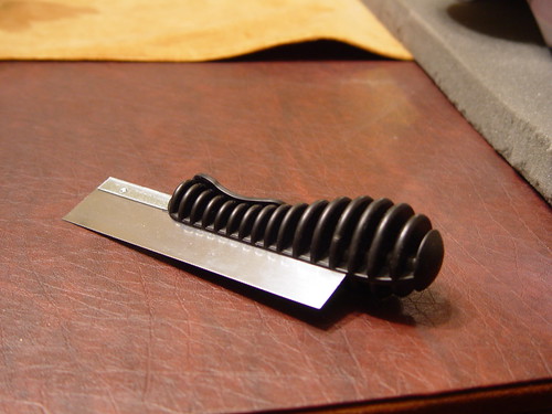
I'll admit. There are cleaner (better) ways of detaching these panels from the main board; however, not knowing what I was going to see, I decided to go with brute force cutting.
I picked up this small saw from a hobby shop.
Took a deep breath and started cutting. As you can tell, the panels have these legs on all 4 corners, so I knew I had to cut through that plus anything else in the middle that was also connected.
I tried my best to keep the saw blade from rubbing against the circuitry in the SureElectronics board.
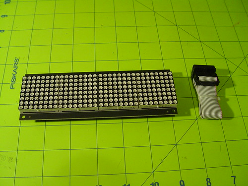
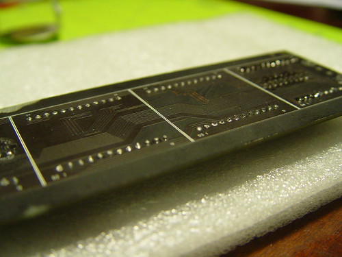
Here's the back of the first removed 8x8 LED panel.
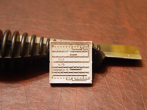
... and here's what is left behind on the SureElectronics board after removing all 4 panels. Notice the white squares on the board outlining the footprint of each panel.
It was extremely difficult to get any sort of voltage and/or amp readings from the main board given that I didn't know what each pin was doing. :confused
So, my next step was to decipher the 8x8 LED panel matrix and see if I got anything out of that using simply trial-and-error method.
I rigged the panel with these angle headers to make it easier to test. Then, using a battery + resistor, I fixed the positive lead to one pin and tested all other pins while looking to see if anything would light up.
Please note that before removing the LED panels, I marked their orientation (top,bottom,left, side). I also marked each with 1,2,.. so the side shown in the picture below is the right side of the first panel.
I had to rig two panels with headers like the one above. Not that I needed two, but my boys thought I was making spider robots.
")
. So each had to have one.
After some more trial and error, I figure out that connections do
not vary from panel to panel. That's a :thumbsup in my book.
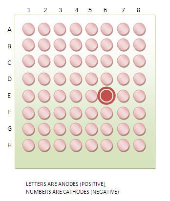
.. and here the answer to the puzzle.
As the picture shows, rows are anodes and columns are cathodes. So if I wanted to light up the shown LED, I would have to connect E(+) and 6(-).
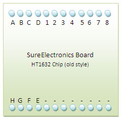
More importantly, here's the same reference, but now from the SureElectronics pins.
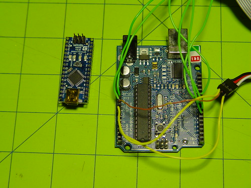
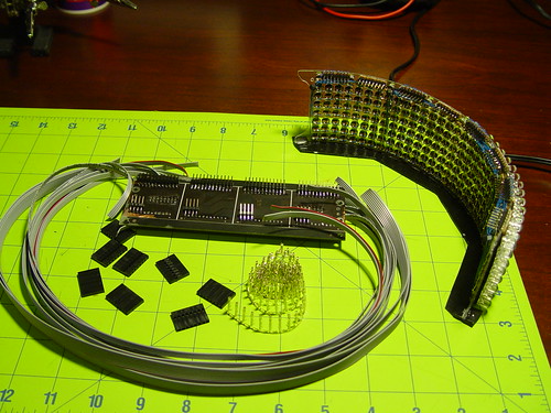
The next step was to make the connections from the SureElectronics board to my matrix using these references.
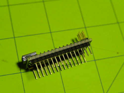
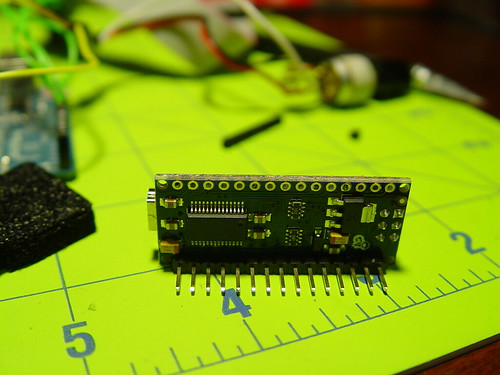
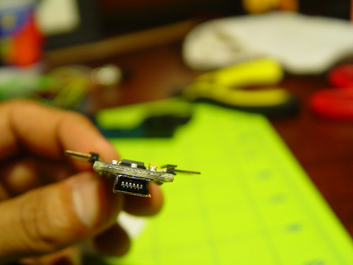
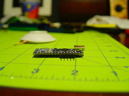
First step was to equip the SureElectronics board with headers
Then, work on the wire harnesses.
more to come.