E-11 model "x" - A BlasTech Case Study (pics intensive)

erv

Well-Known Member
Hi !
I thought I'd share that work here too to get some feedback from the pros.

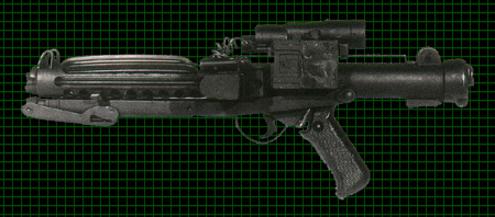
I wanted to make a E-11 for a long time, my customer Pablo and his scratch built did put the scale UP.

I considered screen accurate for a while, but I decided later to go for a custom E-11 since I wanted to add a screen to the blaster, hence non canon (I hope I'm not hurting any feelings).

Rather than scratch built (very tempted to follow that path though), I chose real sterling parts.

Here is the build log with many pics, I though that might interest some of you.

SHORT CUT : here's the video :)

E-11 model X Custom Blaster - 3 videos

The sterling came in chopped pieces which is the short "cut" :))) to disable it. Sure, it won't *ever* work again this way...

The first part of the exercise is to extract all the bits and parts then clean/Shave them and re install them on the main body that will be scratch built. The rest I hope to have as many vintage parts as possible on that blaster. The scope is missing but it is on my way as I'm typing this.

MyE11_001.JPG


cutting the read sight and the removable butt cap
MyE11_002.JPG

MyE11_003.JPG

MyE11_004.JPG


Building the main body. The PVC BBC templates are for a 42mm OD tube matching some plumbing supplies. The real sterling is made out of a 1"1/2 OD tube. I managed to find the right diameter and correct wall too, on ebay.co.uk, tubes being sold as coolant pipes. Made of sturdy 6063 T6 aluminium from what I remember.

The downsizing of the templates are an exact 10%. I shrunk only the width to match the perimeter, holes are oval but since I know what the size is supposed to be (7/16" and a few of 1/2"), so I just needed the alignment and spacing, aside the front stock lock groove that was measured on the original part and cut accordingly.

MyE11_026.JPG

MyE11_027.JPG


I'm so happy I have those stepped drill bits. (In inches :thumbsup)
MyE11_006.JPG


Many centers and drills later...
MyE11_007.JPG


Cutting the long groove
MyE11_009.JPG


Done. Jump for joy. Cool yourself down. And wash your dirty hands you dirty boy.
MyE11_010.JPG


Some sanding to clean the outside. I used a file to clean the sharp metal edges inside, then cleaned the wall of each hole with a sharp knife, then finally put some sand paper on a piece of blade to get a nice finish inside.
Then, some threaded rod and a piece of aluminium matching the ID, with sand paper taped on it => drilling machine => clean shave of the inside of the tube.
MyE11_011.JPG


I was impressed to see that the bolt is perfectly fitting in that tube !
MyE11_012.JPG


I don't want to have a huge post with everything inside, I'll keep posting the rest of the various stages of the built later !
 
Last edited:
Shaving various parts. Tedious. Don't know what God modeled after him but he had some smart enlightenment when he got B&D inventing the electric file. Let there be steel powder. This is the front flash deflector
MyE11_014.JPG


Measuring the eject port. Since my templates were shrunk of 10%, I rubbed some grunge on a piece of paper to "measure" the original one. Yes, I also used a digital caliper too :confused
MyE11_013.JPG


Extracting the stock mount. Fortunately the pins are coming out easily. Easier than removing those **** on a MR saber :angry
MyE11_015.JPG


Shaving time again. Sorry no Gilette cream. Sorry about the heat. But admit it you look much nicer now.
MyE11_016.JPG

MyE11_017.JPG


fitting like husband and wife (which is never perfect as you know)
MyE11_018.JPG


Rear sight. I'm cheating on that one, I'll leave a superficial layer of the original body tube to have a large flat surface for the JB weld to stick on (+ a headless screw or 2, or simply JBweld rivets). No one will notice a 2/10th mm difference in the part height.
MyE11_019.JPG

MyE11_020.JPG


The handle and trigger group holder. Same as above. Some is cut out but I leave some surface for the attachment. No point of having that section fragile.
MyE11_021.JPG


Cleaning the muzzle. I got a HARD time extracting it. Then I machined it. Fits the barrel like a charm (supposed to).
MyE11_022.JPG


What I have to re install
MyE11_025.JPG


The butt will be coupled to the main body by just machining both parts (reducing a little bit the body OD on a 1" sleeve, and increasing a bit the ID of the rear ring, then JBweld)invisible. Electronics will remain accessible from the rear.

I've identified how I'll handle the blast and the semi/full auto mode, using the the REAL SELECTOR and trigger. Very easy. More detail on that later. I also have some glams idea.
 
Sweet build - i received two days ago my E-11 from a real Sterling, but i hope to find some day the time to make another from scratch, too (with light and sound). Your buildup will be helpfull then, i think. :cool

May i ask why you mix the materials Steel and Alu? All the work with separating the parts to the needed shape to fit them to a alu-tube, why not separating the existing real parts to fit to be brazed on a new steel-tube?
 
May i ask why you mix the materials Steel and Alu? All the work with separating the parts to the needed shape to fit them to a alu-tube, why not separating the existing real parts to fit to be brazed on a new steel-tube?

thanks ! and good questions too. The choice of alu is due to my location. You just can't imagine how it's hard (or extremely expensive) to buy metal in here, plus with the metric system, the closest size were either 35 or 40 mm. Then I don't have TIG welding equipment, so I did it this way.
I've seen another project where the member brazed the parts together, I was very impressed on how good looking the sterling ended.

the kit I got was chopped this way
xb1008.jpg


Even getting alu tubes in the UK shipped to me wasn't that easy, since it's heavy and not all vendors will accept to ship across the channel :confused Also, with the humble machining tools I have, alu remained the easiest solution.

here's some more of the build log. I wanted to have the blaster Powder Coated cause I like props you can hang around with, without the fear of paint chipping and so forth.

2 stressful days cause I was SO afraid to miss the PC job. I first went to buy some oxalic acid (you guys call that Naval Jelly, rust dissolver) to prep things nicely. I also baked the folding stock and the main body since I noticed it helped neutralizing the rest of paints, oil and so forth.
Baking also gave the final kick to the steel epoxy on the main body, which stabilized and didn't melt at all.

Then I cleaned with water, then with biodegradable degreaser, and wiped properly, then compressed air to blow away any trace of moisture.

I resisted to the envy to re coat the folding stock (an area isn't thick enough) but I didn't. Too risky.

First, I remembered about the faraday effect during the PC job, and I was worried about not having the inside of the barrel dark enough. So I protected the beast and PCed the inside with a light mist of flat black (then I hadn't made more experiments with the satin black I had and I didn't want to ruin anything).
MyE11_045.JPG


then after experimenting the right flow out time and temp on a scrap part,
I played again with the satin black on the trigger and its guard. I learned there how to (almost) fully disassemble a trigger group, which helped for cleaning it from all the grease.
MyE11_046.JPG


PCing the folding stock. First stress of the day
MyE11_047.JPG


final results once I've baked all the parts (the oven heated the whole afternoon, I couldn't stop). I also made my scope rail.
MyE11_048.JPG


Still a light texture but that's exactly what I wanted
MyE11_049.JPG


You can see the difference in the texture of the butt cap. It's not just due to the primer coat of flat black, the surface of the metal was different.
MyE11_050.JPG


Stock locks (and 2 smoking barrels :lol)
MyE11_051.JPG

MyE11_052.JPG


MyE11_053.JPG


the shorten magazine
MyE11_054.JPG


with a nice decorative inserts (SO-dim 1GB... well that's only 512 MB now :rolleyes - They didn't want it back at work after I upgraded on my previous machine)
MyE11_055.JPG


Getting close. Received my uber accurate T-tracks from Gino yesterday. Strong ABS extruded plastic with the right gaussian profile.

Grinding the bolt. Why ? because it's hiding something (see below). Taking a picture while actually grinding isn't easy when you have only 2 hands and no tripod and when you're tired to make efforts... (I know, use the Force to levitate the camera)
MyE11_056.JPG


wiring the satellite board on the barrel. After checking between having it right next to the Blaster Core board or here, it was easier like that, less wires and an easy power supply split for the barrel end flash RGB led. The latter has its power xtender and resistors all local, and protected with heatshrink. Once glued, the LEDs were covered with some masking liquid (latex from what I smell... brand is Maskol by Humbrol), then I painted the whole barrel with some regular satin paint. It's weird to work again with spray paint once you've done some powder coating. Takes ages to dry (impatient me), chips and marks easily buy since it's going INSIDE the body of the E11 so I don't mind.
MyE11_058.JPG

MyE11_059.JPG

MyE11_072.JPG


A big part. A crystal chamber. I wanted to have (among other things) some glams for that projects. Also, the bolt is visually such a nice piece of mechanics that I refused to do a static thing with it, with a piece of chrome tape. So you can still cock the bolt and it moves back to reveal some (simple) internals. I mounted an aqua aura crystal on a small ring/mount JBwelded to the bolt and it goes straight in the barrel.
The internals were assembled on a thin copper plate (polished a bit), the thin comb of brass/gold is an old SD card reader that came with my previous laptop, as well as the control card (sanded, and glued). You can also spot 2 anakin brass pins, a weirdly shaped coil from a hard drive and a few other bits I had in my drawers.

MyE11_067.JPG

MyE11_068.JPG

MyE11_069.JPG

MyE11_070.JPG

MyE11_071.JPG


Once everything was installed, I placed a small headless screw behind the handle to stop the bolt from going back too far (and smashing the wires going in the handle, to the trigger group). It's not moving back a lot, but it's enough to reveal the internals. No led there and no reason you'll have any, getting the bolt back disables the weapon. Initially, I was supposed to use the bolt as a range selector / unjamming operation but I didn't have the right spot to place the sensor/switch and I consider the bolt and wires just behind it too fragile for using that on a standard base.

MyE11_062.JPG

MyE11_063.JPG

MyE11_064.JPG


Installing the electronics in the back. It's one of the most difficult wiring job I ever had to do (my yoda saber retrofit was easy in comparison). Not only there are a LOT of wires but they have to extend to allow servicing the board if need and they have to fold properly when the chassis (PVC) is inserted in the body of the sterling. Add then that you have the functional spring and the bolt that still have to move freely without smashing the wires.
Also, fourteen (14 !) wires are going to the henglser counter. Holy cow. I used some of my 30 AWG ribbon cable. It's a solid wire in there (no strand) but that was my only choice.

MyE11_066.JPG

MyE11_065.JPG


The trigger group. No limit switches, but Hall effect sensors and small neodymium magnets (3mm OD) and secured with activated (spray) cyanoacrylate glue. They act as a switch when the magnet is close enough. Inside, it's actually an open drain MOSFET transistor, just like a power xtender board.
The only switch I used is for the AUX switch (range / reload). I'm going to cut the screw that secure the trigger group to the handle and body and the rounded end (the one not having the screw driver slot) will be attached to the switch plunger (removable). On the other side of the handle, where you read the "Free / Lock", the other half of the screw will go on a M3 head less screw that installed on a small bolt then glued on the back of the aux switch with some JBweld. Original Look will be preserved.
MyE11_060.JPG

MyE11_061.JPG


more to come, I've taken about 110 pics during that build log :confused
 
Last edited:
thanks !

Mag cylinders ! Thumbs up for Russrep accurate pictures he posted in his thread, I did my best to get a scale out of them, but credits go to his work.

MyE11_099.JPG


aligning the lasers took a while, even now it's not perfect but since the magazine catch isn't laying flat on the weapon itself, the targeting sensor laser beams are never aligned. I like it too, it's just point at 2 different location of the target.

MyE11_100.JPG

MyE11_101.JPG


Now we know pretty much the parts (but not the source device - read here my recent "research" as Private Erv' http://www.therpf.com/f9/sterling-mag-cylinder-mystery-20345/)

but still, I couldn't find any suitable replicas of the central capacitors in my drawers. The original ones are rated for 70° and won't have withstood PC curing at 400°F so no regrets, I machined cylinders that look like them pretty close.

I happened to play with the PBTP satin and *when cured at the right temp* it's definitely more gloss than the eastwood PC. Flow is just perfect. However it wasn't matching the gloss of the rest of the blaster so I used a coat of an automotive paint that has very little gloss (same as on the T-Track). I left the front cap and nut natural, I like contrasting metal and it really marks the "special X model" of the blaster

MyE11_102.JPG

MyE11_103.JPG

MyE11_104.JPG

MyE11_105.JPG
 
Amazing job!
I can't beleive all the detail you put into the crystal reveal.
How does it feel - all thoe authentic metal parts?

You are truly an artist my friend.
 
thanks a lot !
For the crystal, it's made out of real quartz (aqua aura), I thought it could be the collimating element for the plasma, crystals evocate optical / light stuff.
At the end it's kind of coherent with the wookiepedia article

Blaster - Wookieepedia, the Star Wars Wiki


Testing the trigger group before final install in the handle. You can spot the aux. switch in the axis of the locking screw that is going to be parted in 2 halves.
MyE11_073.JPG


the half that will go on the back of the aux. switch (I installed a small M3 screw there)
MyE11_074.JPG


installed and it screws fine to the "lock" position as read on the handle
MyE11_075.JPG


The other half of the screw, mounted & screwed on the switch cap/plunger.
MyE11_078.JPG

MyE11_076.JPG


I used some anti mosquito mesh / lattice that I powder coated with black chrome II. Then I glued some black fabric tape with a glue spray to hide the electronics. I looks a bit like a carbon mesh (not exactly, just the "style"). I like it very much.

MyE11_077.JPG


Worked on the T-track I got from Gino. Bent with a lighter, smoothed with gentle heat and finger, then sanded at the ends. Painted flat black with automotive paint, glued with a few spots of epoxy, except the top one since it blocks the scope rail from being removed and I still need to install the scope (it's mounted with magnets so that it's easily removable)

MyE11_081.JPG

MyE11_098.JPG


Folding stock installed. Replaced the nails by 2 stainless steel M2 screws. Not sure I'll paint them black, I like the steel accents.
MyE11_082.JPG


Reworking the firmware. I had ideas that were not ready for that release, but I wanted to prototype some of them for my E11. Hence, I made sure I had a flashing connector accessible from the rear of the blaster.
MyE11_080.JPG


Milled a slot in the henglser counter. Why ? because there's something else requiring potentially some upgrade too.
MyE11_079.JPG


... A mini screen... The side of the counter has some dirty edges. That's due to the PC job I ****ed up with the Eastwood powder. Not having the right stripper made my like VERY difficult on that one. I thought I had removed everything but no (of course). Not "ugly" but could be better. Too late :unsure
Boot sequence featuring a imperial logo being filled up. I shortened the boot sound of 20%-ish to get it perfectly synched with the boot animation.
MyE11_087.JPG


Custom title of that one, the "E-11-X"
MyE11_086.JPG


Front side of the counter. I kept the optic it makes the 3mm leds occupying the whole space and they look a bit oval, I like it. The reset button of the counter is now the menu switch to browse thru the different screen of blaster core.
MyE11_089.JPG


Radar screen and ammo counter
MyE11_091.JPG

MyE11_090.JPG


Screen saver. It's blurrier than a normal screen due to the export of the video, but it looks better in person
MyE11_092.JPG


I added 3 new "menus" to the firmware.
My counter wasn't the "right one" with the Eagle Logo, reason why I had no remorse cutting a window for the screen. However, I felt nostalgic about it so I mocked up a digital version.
MyE11_093.JPG


Another screen with a static imperial logo (always efficient and iconographic)
MyE11_094.JPG


Last screen, a system info displaying the charge and voltage of the battery (the config file has 2 PLI settings for that purpose). I also had fun with some extra verbiage on that one.
The cell/battery icon on the left isn't depleted in real time to avoid flickering on the sprite but it's updated each time you pass in the menu. The voltage and the charge % is updated in real time though, and you see it fluctuating a bit when you fire.
MyE11_095.JPG


I did my best for the details. Wires (ribbon cable) going to the counter are hiden in a black mesh tubbing. Quite organic, my favorite. I also put some of the anti mosquito mesh to hide a bit the second speaker that is in there.
MyE11_096.JPG


Same on the front of the counter. I also put a screw head and a small crystal to hide the hole left by the removal of the reset mechanism of the counter.
MyE11_097.JPG


The wires coming out from the counter will be really used. I've always thought that the magazine cylinders should be some kind of smart targeting system (obviously not "finished" since the blasters end beaten by the sabers). Since it's the E-11-X I could invent anything after all.
I'm therefore installing 2 red lasers in the mag cylinders. They are controlled by the rear sight mechanism. I got that idea from the very beginning and that's why I wanted to make THIS very model of blaster : wire from counter to mag cylinders and scope rail stopping BEFORE the sight.
Like here
e11b.JPG


To avoid any switch between the outside of the main body and the internal electronics, I used (again) a hall effect sensor, installed in the PVC chassis. 2 magnets inline are installed in the scope reticule that activates the lasers in the "accurate aiming" position of the sight.
MyE11_080.JPG


The stand. I got the smoked plates for free. I discovered later that it's polycarbonate, 1 cm thick, I got many panels it's worth a fortune. Attached 2 pieces together and made the stand with it. PCed legs with accent rings (quick cut with the lathe).
I still have to make a galv-etched plate now that I have the resist photo film

MyE11_106.JPG

MyE11_107.JPG

MyE11_108.JPG


and finally,
video time. Sorry for the length, I really think I had to detail that one.

E-11 model X Custom Blaster - 3 videos
 
Gee, I was all excited because I got the square cut out on the counter to show the "Eagle" symbol today. Yippi:angry:angry:angry

I second the notion. Best blaster ever. I hate you:cry:cry:cry:cry

When are you gonna offer some for sale???????:love:love:love
 
This thread is more than 13 years old.

Your message may be considered spam for the following reasons:

  1. This thread hasn't been active in some time. A new post in this thread might not contribute constructively to this discussion after so long.
If you wish to reply despite these issues, check the box below before replying.
Be aware that malicious compliance may result in more severe penalties.
Back
Top