Shaw
Well-Known Member
Background
Back in 2007 I spent a little time cleaning up the one-to-one scale plans of the Phase II Enterprise studio model (which can be found here). The model would have been about 5 feet 4 inches long when completed, and between photos of the studio model under construction and additional drawings by Jefferies, I thought there might be enough information for an accurate set of plans. What I found shortly after starting work on the project was that the gaps in data were fairly large and that filling them would require me to inject my own artistic choices. This was something I absolutely wouldn't do as I've always felt that my work should be research and documentation, but should have as little to do with me as possible because I wasn't part of Star Trek (and I believe that people who weren't there shouldn't be trying to write themselves into the subject). So the project was shelved with the hope of one day returning to it to finally flesh out the details that were missing.
This last summer I started looking over the project again, and outlining what I would need to do to bring this to fruition. I had set my sights on restarting it by the summer of 2013.
About a month ago all that changed. I was contacted by someone willing to provide the details I would need to go forward... unfortunately, it was before I was prepared to step back into the project. I've since been going back through my notes and source materials to get back up to speed on the subject.
Study Model
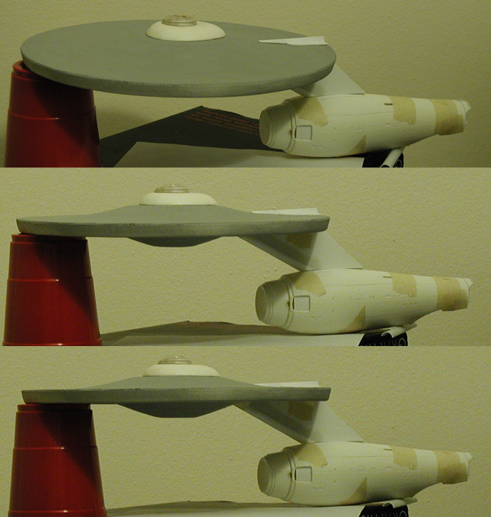
I work better with a three dimensional (physical) representation of a subject I'm studying... plus I like models. The two attempts I made at replicating the original 33 inch Enterprise (at two-thirds scale) were done to help me with plans of that model, which in turn were leading to a one-to-one scale replica once I felt like the plans were accurate enough. And I had planned on starting that build before December.
Even though much of the two smaller scale attempts were scratch built, what I was planning on in building a full size replica would have included building techniques I hadn't done before. And I was apprehensive about experimenting with those techniques on a model with parts that large (where screwing up could get expensive very fast).
So between the need for a study model for the Phase II Enterprise project and a project that would let me test some building techniques on a smaller scale, this model got pushed to the front of the build list.
Because this is a study model, I wanted to reduce the work as much as possible. The obvious choice was to use another model as a starting point, and as the TMP Refit Enterprise was actually built on the foundations of the Phase II Enterprise, it seemed like an obvious choice.
I decided on the AMT/ERTL Refit model over the Polar Lights/Round 2 Refit because of price (both of the kit itself and the additional cost of building larger parts). The only parts to be used would be the primary hull and secondary hull, both heavily modified. The rest of the model would be scratch built.
I'm not sure how others approach this type of build, but I'm firmly from the school of measure twice, cut once model building. So to start this model off, I've been spending my time reinterpreting Jefferies' plans into a form that will help me build this model. This includes how parts from the AMT/ERTL Refit will need to be altered and how any parts that will be scratch built will connect to either of the preexisting sections.
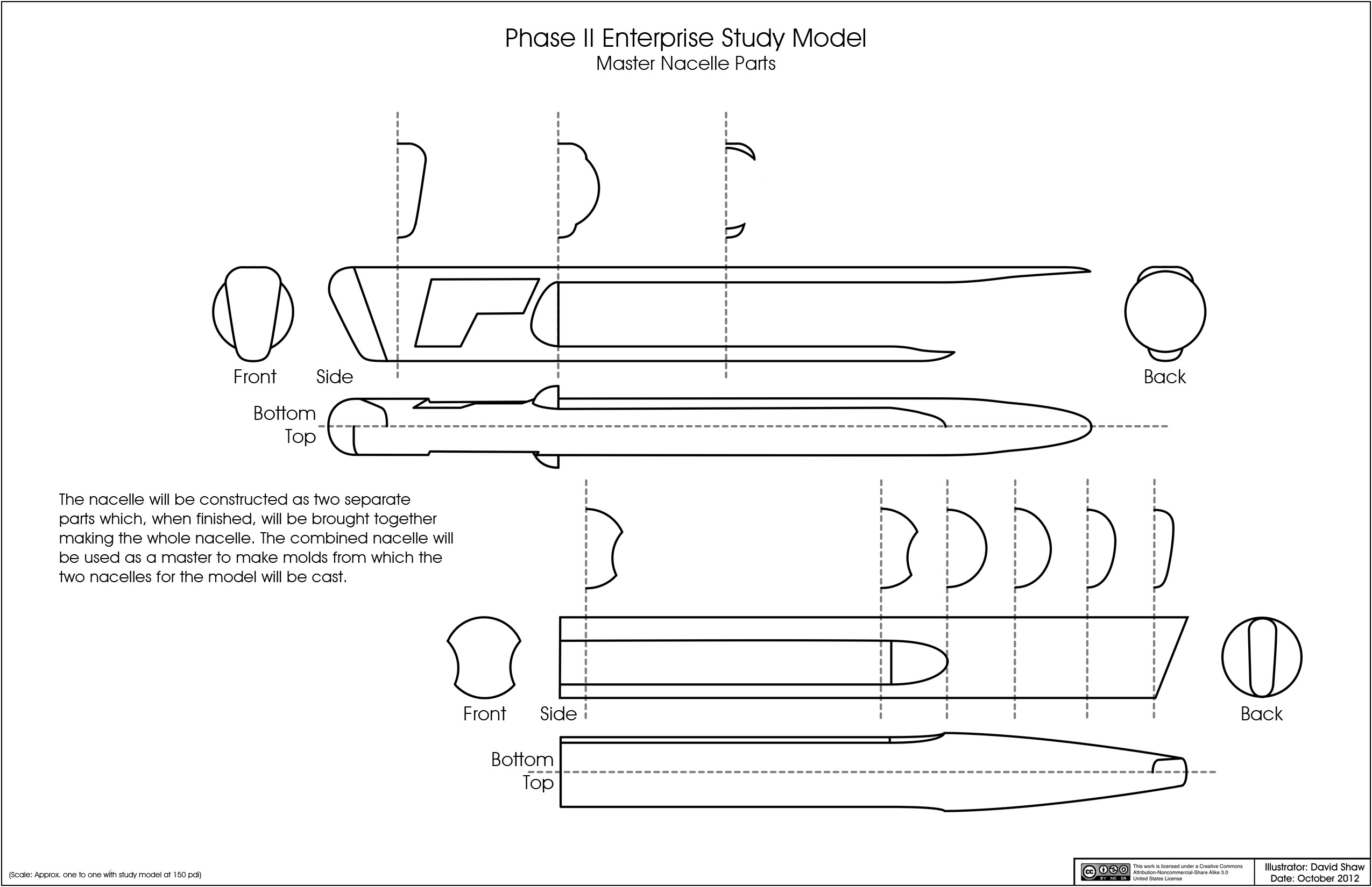
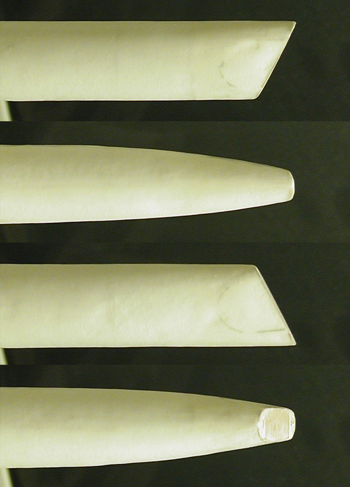
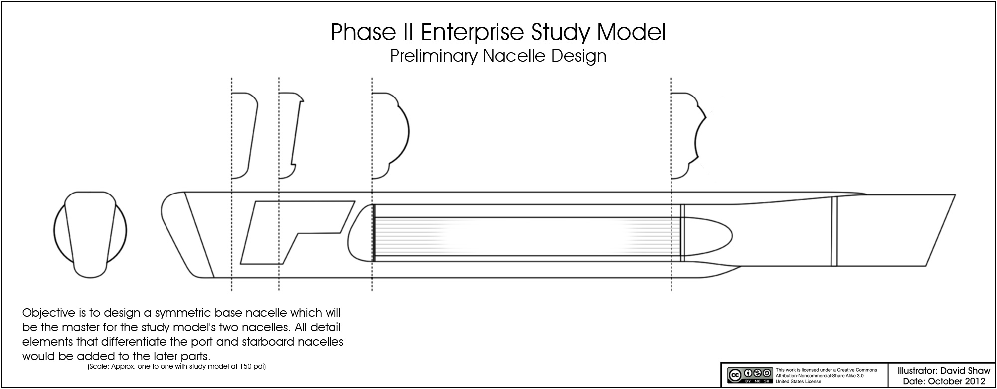
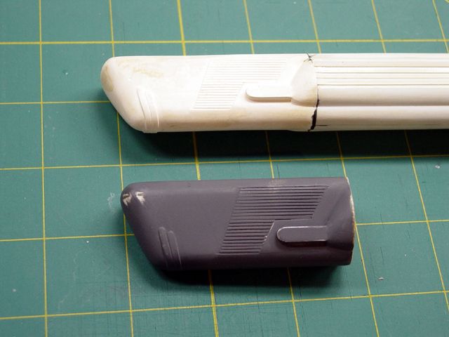
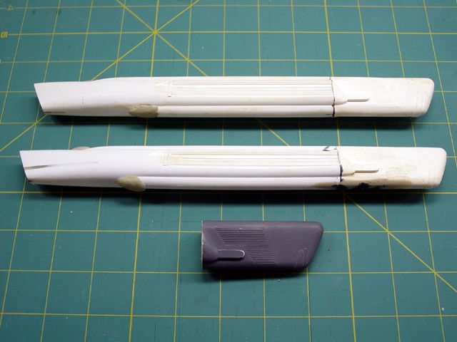
One of the areas that had bothered me the most back in 2007 was the design of the nacelles, so I'm starting with them. Studying the design of the nacelles, I've tried to strip away any elements that define if the nacelle is port or starboard, and concentrate on building a symmetric foundation nacelle. This can then be used to make two copies and I'd add the unique elements to those to make them either port or starboard. This is my preliminary nacelle design...
This sketch more closely resembles the geometry of the Brick Price/Don Loos miniature than the Jefferies plans (even though they are mostly based on measurements from the Jefferies plans).
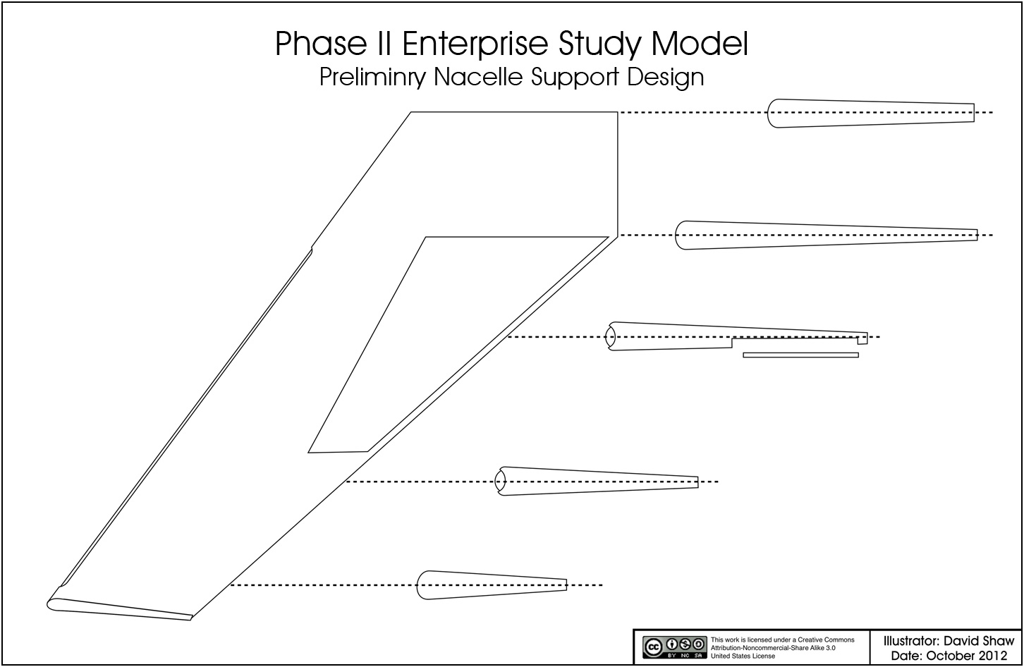
Next I started in on the nacelle supports, translating them to drawings that would be easier to build from.
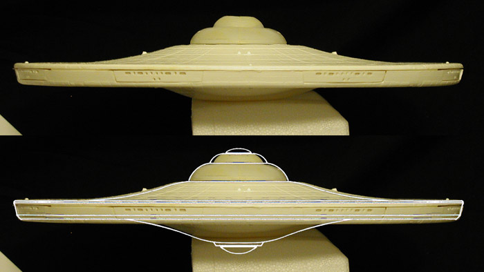
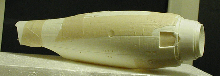
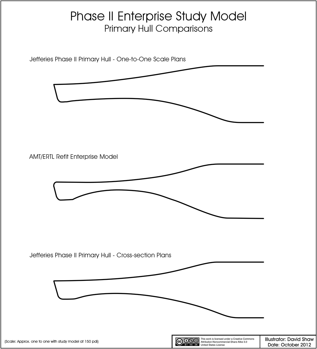
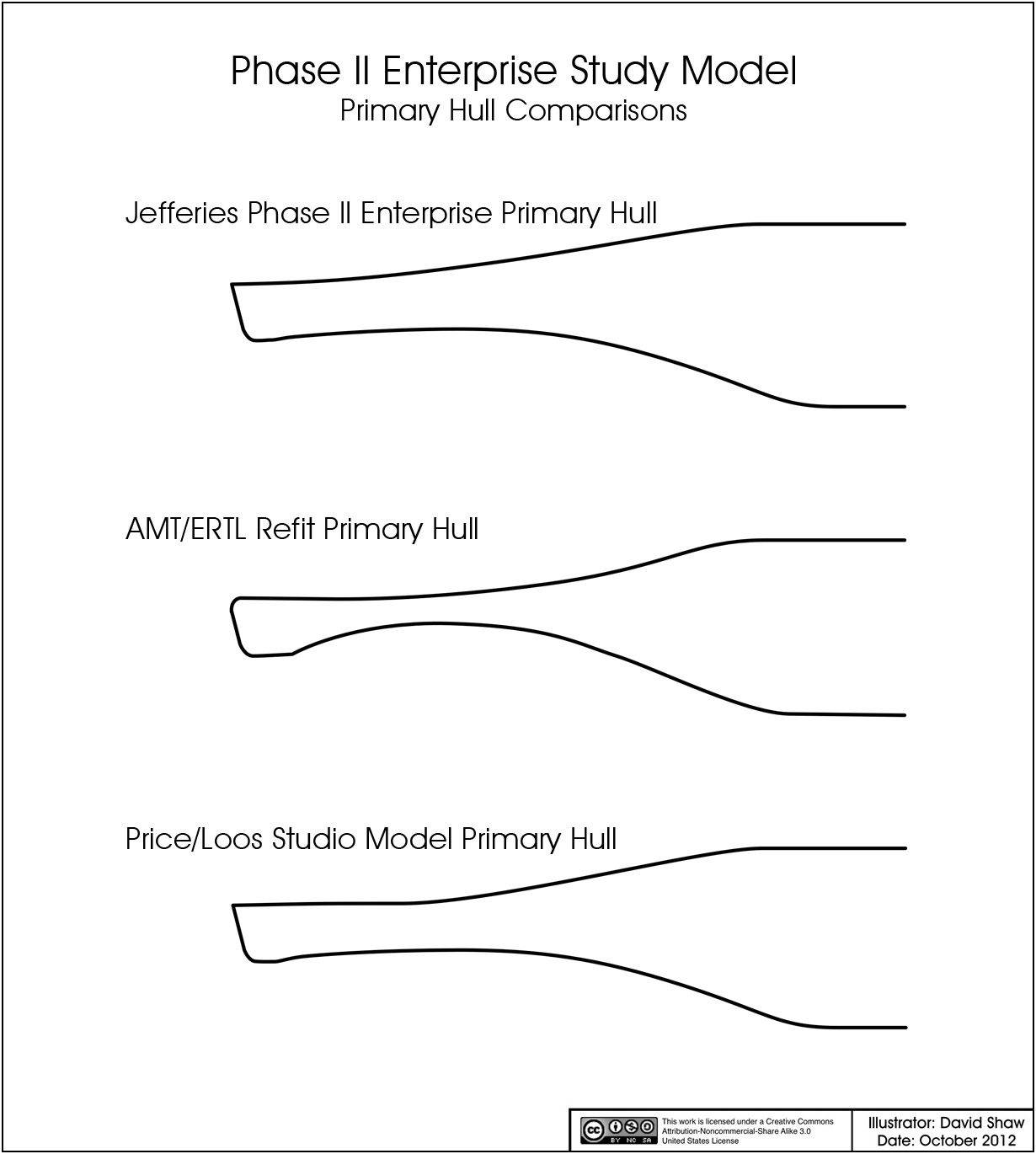
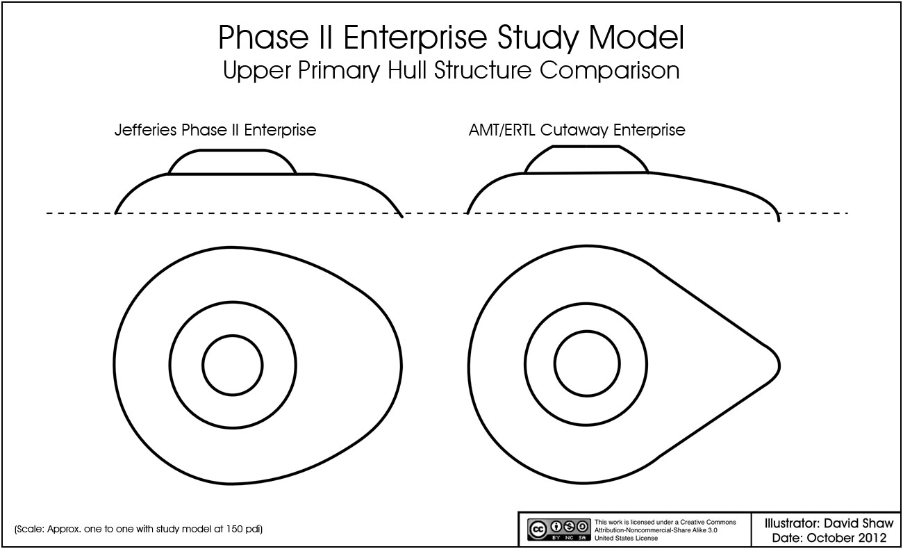
By this point I had had enough time to get an AMT/ERTL Refit model and to bring important data about the parts geometry into my computer so I could start working all the elements together. My initial assessment of how the AMT/ERTL Refit parts would work were based on plans of the TMP Refit model. Unfortunately, the geometry of the AMT/ERTL Refit differs by quite a bit. When I saw how far off the AMT/ERTL Refit primary hull cross-section was from that of the Jefferies plans for the studio model, I was worried that I might have to consider scratch building the primary hull (which I've now done twice, once for each of my 33 inch Enterprise replica attempts). Fortunately, Jefferies had a number of drawings of the Phase II Enterprise, and the AMT/ERTL Refit cross-section wasn't too far off from one of the other Jefferies' drawings.
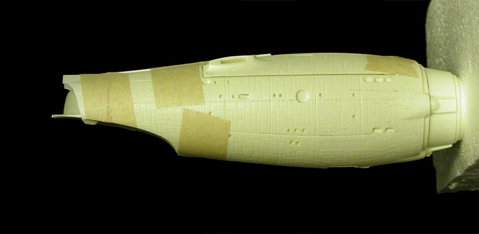
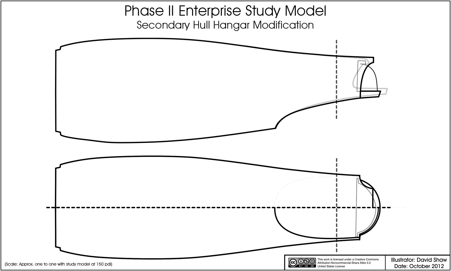
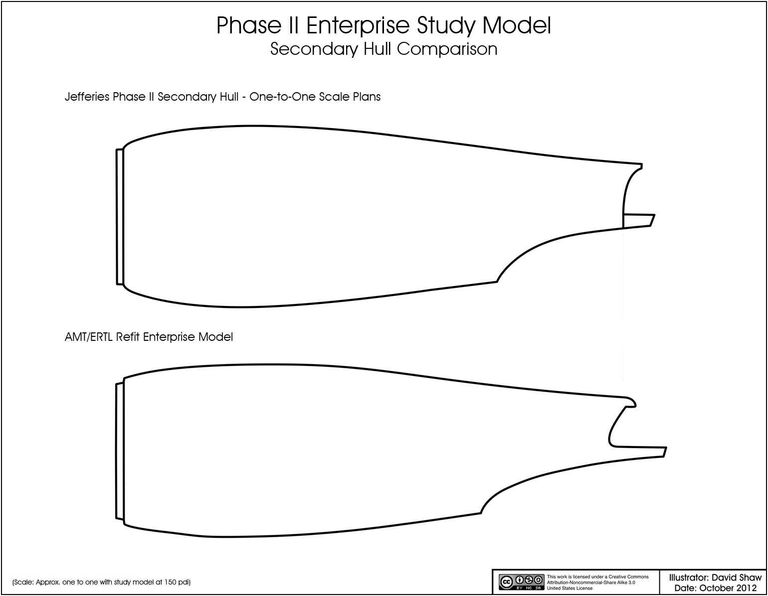
The secondary hull wasn't too much better, as I was hoping to have more room to work with in the hangar deck area. Still, I had replaced the hangar doors, deck and undercut on my last Enterprise model, so I'm not too worried about having to do the same in this case.
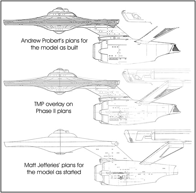
When I started looking at the dorsal, I came across another geometry issue. The dorsal as designed by Jefferies in the full scale plans was different than the dorsal as built by Price/Loos (though other drawings by Jefferies could be interpreted as how the studio model was built).
After studying the various versions, I decided to stick with Jefferies' original design for this model... mainly because I think it'll be easier to work with when adding the torpedo assembly housing later on. This is how I plan on building the dorsal (the primary and secondary hull contours are from the AMT/ERTL Refit)...
I included the AMT/ERTL Refit's dorsal as a comparison because I know that some people have suggested that it could be used because it has a similar profile, but the parts over all geometry is too far removed from what I need to be used (even as a starting point).
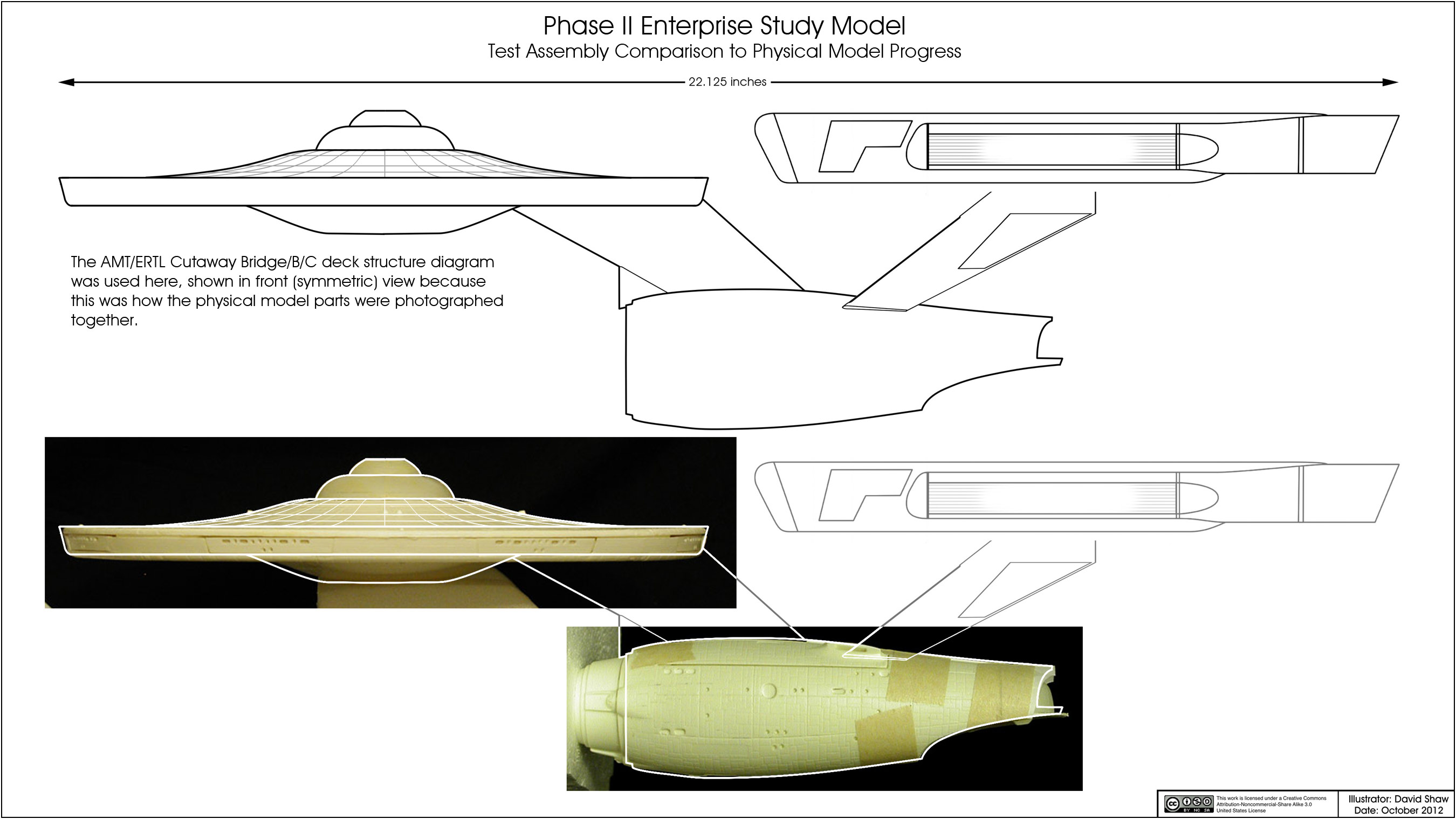
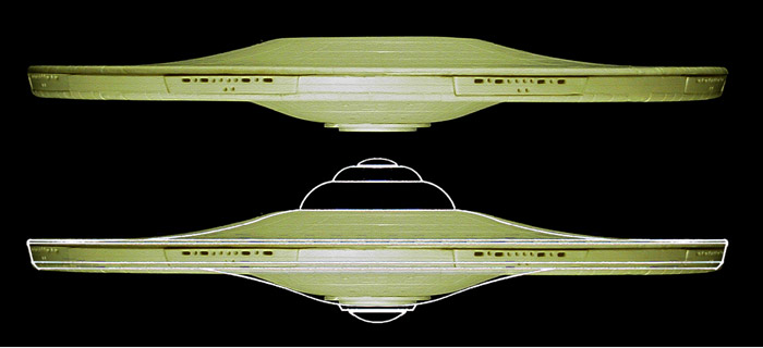
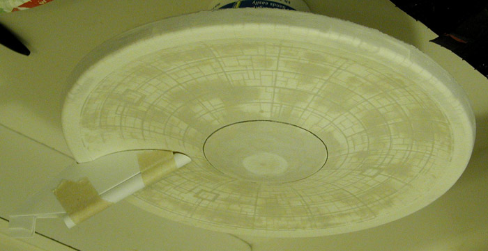
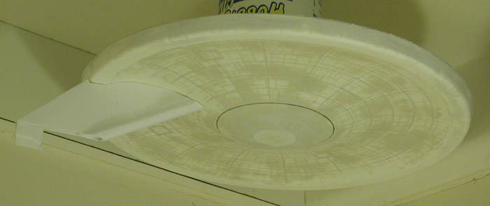
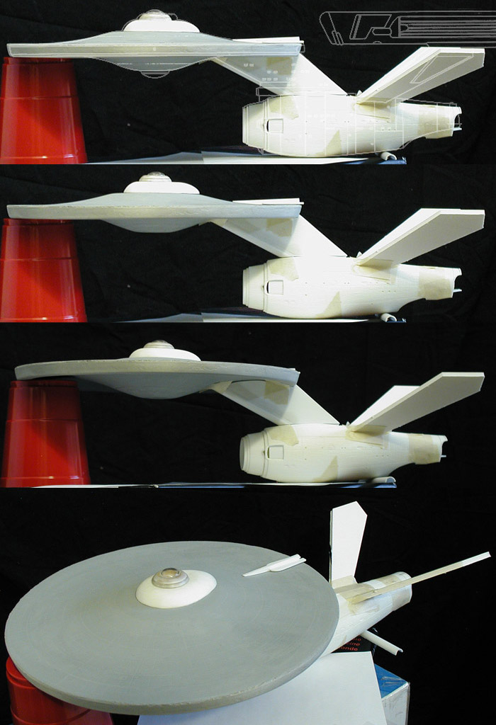
With these elements, I decided I had enough to do a quick-n-dirty test assembly to see how everything was coming together.
In the drawing above I included modifications to the AMT/ERTL Refit parts I planned on making and a copy of Jefferies studio model plans for comparison. What I've taken away from this test assembly is that things are going about how I planned, but that the bottom of the primary hull needs to be extended down and the plateau should be smaller (which isn't that hard a fix).
So that is where I'm currently at... mainly in the planning stages, trying to address issues before I encounter them during the actual physical build.
Back in 2007 I spent a little time cleaning up the one-to-one scale plans of the Phase II Enterprise studio model (which can be found here). The model would have been about 5 feet 4 inches long when completed, and between photos of the studio model under construction and additional drawings by Jefferies, I thought there might be enough information for an accurate set of plans. What I found shortly after starting work on the project was that the gaps in data were fairly large and that filling them would require me to inject my own artistic choices. This was something I absolutely wouldn't do as I've always felt that my work should be research and documentation, but should have as little to do with me as possible because I wasn't part of Star Trek (and I believe that people who weren't there shouldn't be trying to write themselves into the subject). So the project was shelved with the hope of one day returning to it to finally flesh out the details that were missing.
This last summer I started looking over the project again, and outlining what I would need to do to bring this to fruition. I had set my sights on restarting it by the summer of 2013.
About a month ago all that changed. I was contacted by someone willing to provide the details I would need to go forward... unfortunately, it was before I was prepared to step back into the project. I've since been going back through my notes and source materials to get back up to speed on the subject.
Study Model
I work better with a three dimensional (physical) representation of a subject I'm studying... plus I like models. The two attempts I made at replicating the original 33 inch Enterprise (at two-thirds scale) were done to help me with plans of that model, which in turn were leading to a one-to-one scale replica once I felt like the plans were accurate enough. And I had planned on starting that build before December.
Even though much of the two smaller scale attempts were scratch built, what I was planning on in building a full size replica would have included building techniques I hadn't done before. And I was apprehensive about experimenting with those techniques on a model with parts that large (where screwing up could get expensive very fast).
So between the need for a study model for the Phase II Enterprise project and a project that would let me test some building techniques on a smaller scale, this model got pushed to the front of the build list.
Because this is a study model, I wanted to reduce the work as much as possible. The obvious choice was to use another model as a starting point, and as the TMP Refit Enterprise was actually built on the foundations of the Phase II Enterprise, it seemed like an obvious choice.
I decided on the AMT/ERTL Refit model over the Polar Lights/Round 2 Refit because of price (both of the kit itself and the additional cost of building larger parts). The only parts to be used would be the primary hull and secondary hull, both heavily modified. The rest of the model would be scratch built.
I'm not sure how others approach this type of build, but I'm firmly from the school of measure twice, cut once model building. So to start this model off, I've been spending my time reinterpreting Jefferies' plans into a form that will help me build this model. This includes how parts from the AMT/ERTL Refit will need to be altered and how any parts that will be scratch built will connect to either of the preexisting sections.
One of the areas that had bothered me the most back in 2007 was the design of the nacelles, so I'm starting with them. Studying the design of the nacelles, I've tried to strip away any elements that define if the nacelle is port or starboard, and concentrate on building a symmetric foundation nacelle. This can then be used to make two copies and I'd add the unique elements to those to make them either port or starboard. This is my preliminary nacelle design...
This sketch more closely resembles the geometry of the Brick Price/Don Loos miniature than the Jefferies plans (even though they are mostly based on measurements from the Jefferies plans).
Next I started in on the nacelle supports, translating them to drawings that would be easier to build from.
By this point I had had enough time to get an AMT/ERTL Refit model and to bring important data about the parts geometry into my computer so I could start working all the elements together. My initial assessment of how the AMT/ERTL Refit parts would work were based on plans of the TMP Refit model. Unfortunately, the geometry of the AMT/ERTL Refit differs by quite a bit. When I saw how far off the AMT/ERTL Refit primary hull cross-section was from that of the Jefferies plans for the studio model, I was worried that I might have to consider scratch building the primary hull (which I've now done twice, once for each of my 33 inch Enterprise replica attempts). Fortunately, Jefferies had a number of drawings of the Phase II Enterprise, and the AMT/ERTL Refit cross-section wasn't too far off from one of the other Jefferies' drawings.
The secondary hull wasn't too much better, as I was hoping to have more room to work with in the hangar deck area. Still, I had replaced the hangar doors, deck and undercut on my last Enterprise model, so I'm not too worried about having to do the same in this case.
When I started looking at the dorsal, I came across another geometry issue. The dorsal as designed by Jefferies in the full scale plans was different than the dorsal as built by Price/Loos (though other drawings by Jefferies could be interpreted as how the studio model was built).
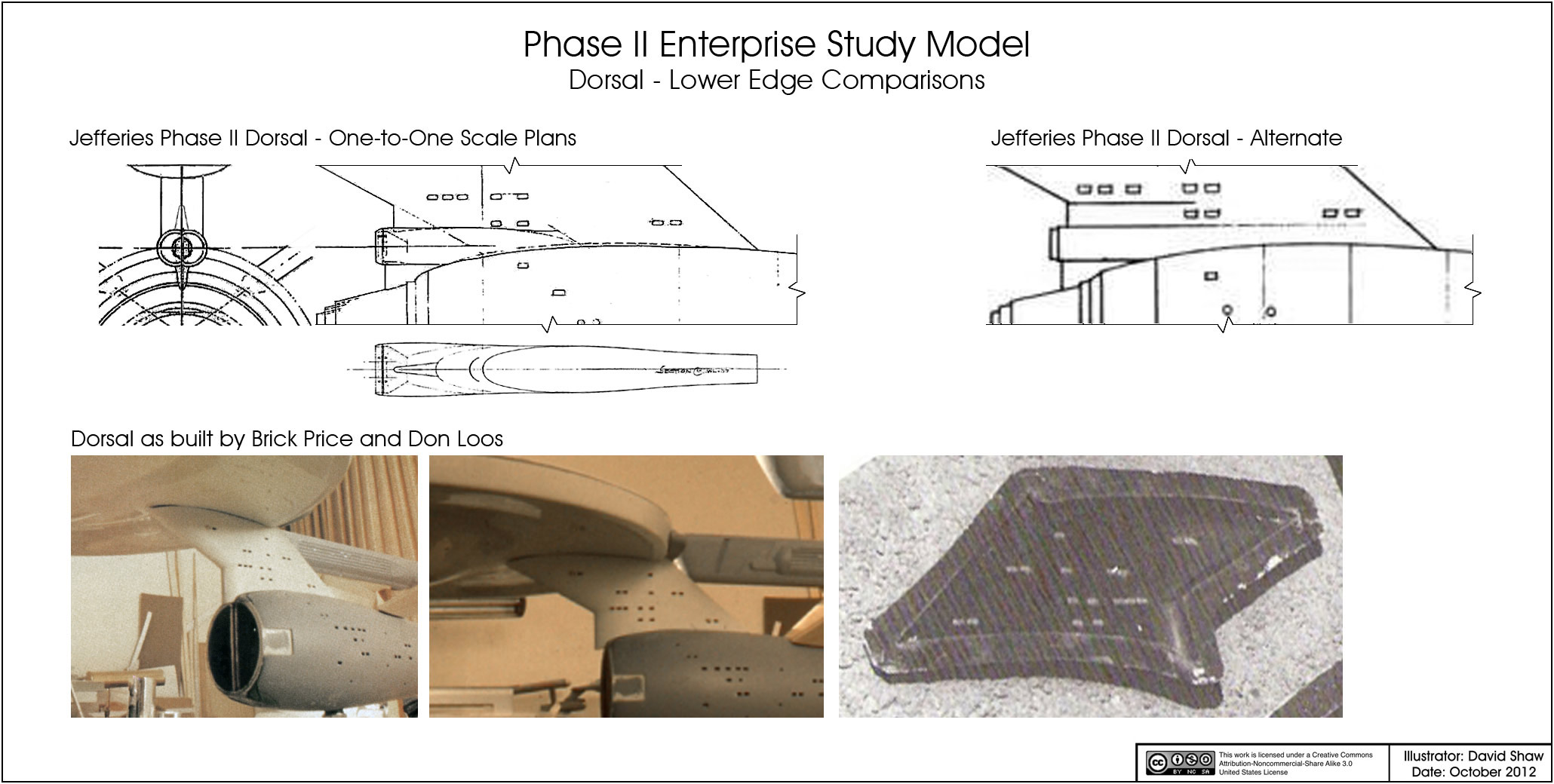
After studying the various versions, I decided to stick with Jefferies' original design for this model... mainly because I think it'll be easier to work with when adding the torpedo assembly housing later on. This is how I plan on building the dorsal (the primary and secondary hull contours are from the AMT/ERTL Refit)...
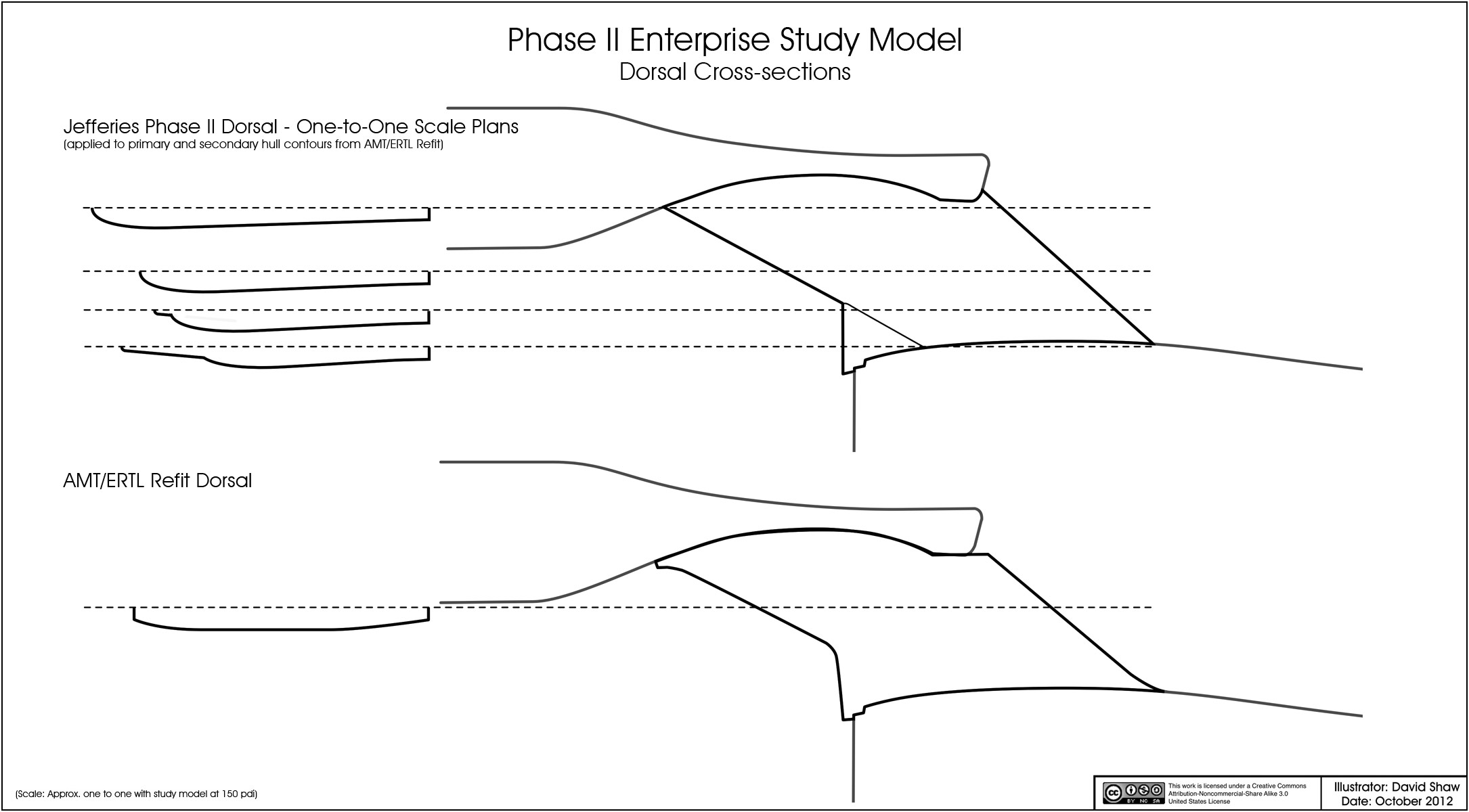
I included the AMT/ERTL Refit's dorsal as a comparison because I know that some people have suggested that it could be used because it has a similar profile, but the parts over all geometry is too far removed from what I need to be used (even as a starting point).
With these elements, I decided I had enough to do a quick-n-dirty test assembly to see how everything was coming together.
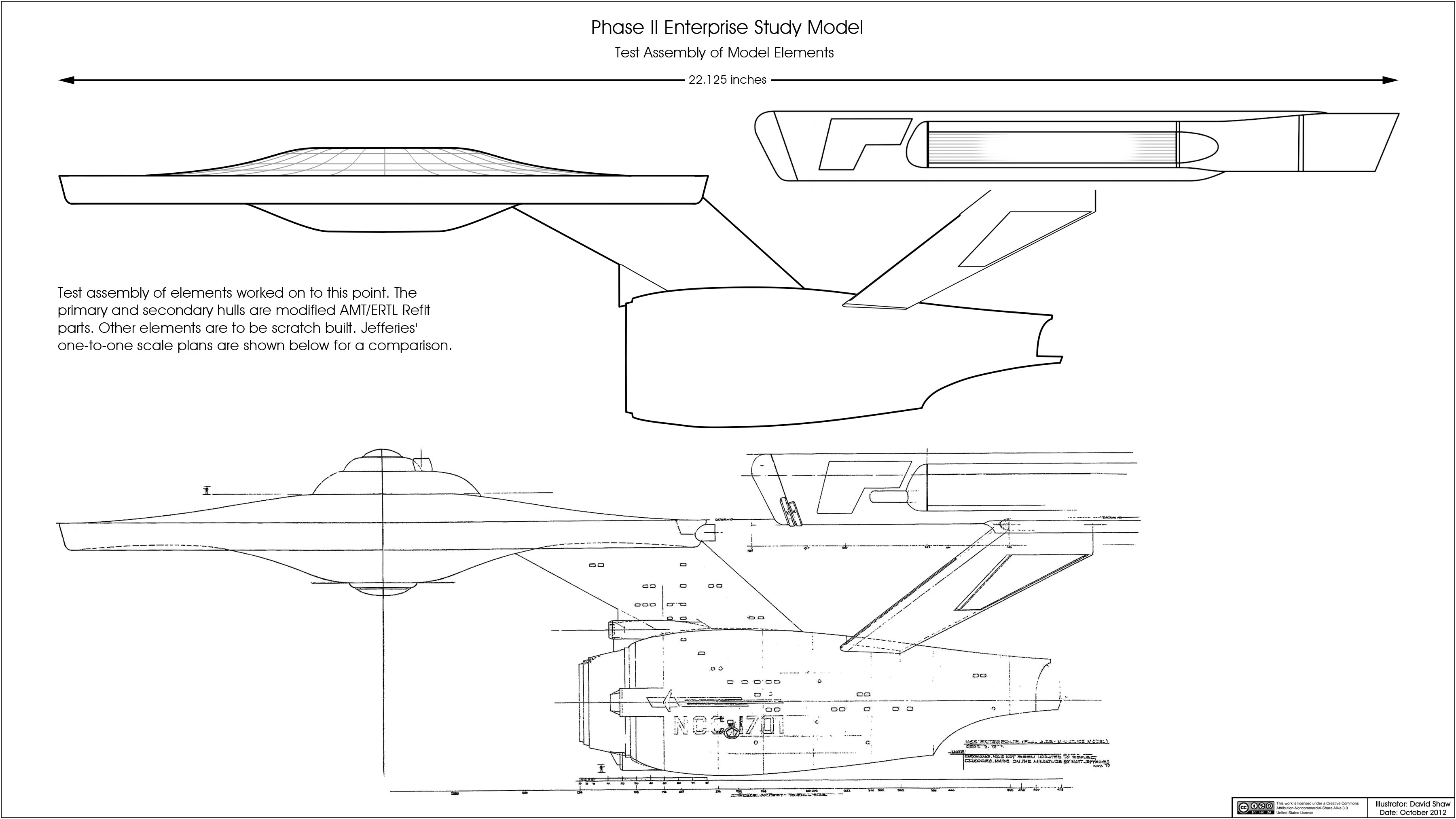
In the drawing above I included modifications to the AMT/ERTL Refit parts I planned on making and a copy of Jefferies studio model plans for comparison. What I've taken away from this test assembly is that things are going about how I planned, but that the bottom of the primary hull needs to be extended down and the plateau should be smaller (which isn't that hard a fix).
So that is where I'm currently at... mainly in the planning stages, trying to address issues before I encounter them during the actual physical build.
")