I thought I had posted this saber build here, but turns out I haven't...

Image property of BioWare
My wife wants me to make her the double bladed lightsaber that the Jedi Consular uses in BioWare's HOPE trailer for The Old Republic. This saber has been a challenge to begin, as I am not sure how to make the intricate details of the handle section. However, the rest of the saber isn't easy either. For instance, the emitters...
To start with, I decided to take some time and attempt to fashion the emitter ends from a section of scrap stainless steel tubing. I chose stainless over aluminum, because of the way the saber is rendered in the trailer, seems more fitting a finish in the long run than aluminum.
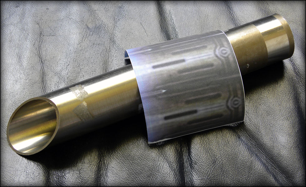
I took the screen capture above and blew it up in photoshop, duplicating it across the appropriate size paper to wrap around the diameter of the tubing.
This wraps around perfectly, and seems to look about right. However, I noticed it would be kind of hard to drill through that, so I used that image as a basis for a template that I printed out and replaced the old one with.
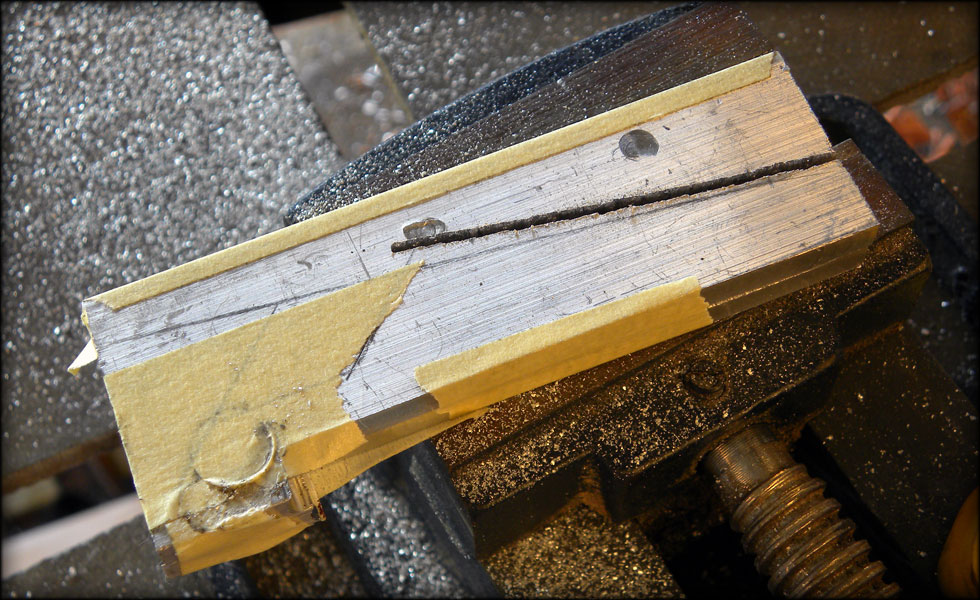
This marks my drill points, and groove for the back of the emitter.
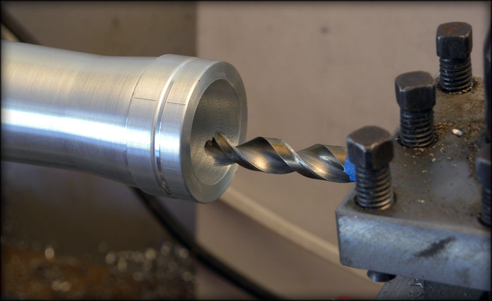
Problem #1 - Holes drilled by hand on curved surfaces tend to wander the drill bit... a bit. Therefore making the holes not quite lined up perfectly. This is a problem, as I will have to connect the holes with slots to form the slots evident in the saber emitter, and they have to be straight, uniform, consistent and even. But, even though I know I will probably have to re do this part, I decide to forge ahead and see what I will learn by finishing it.
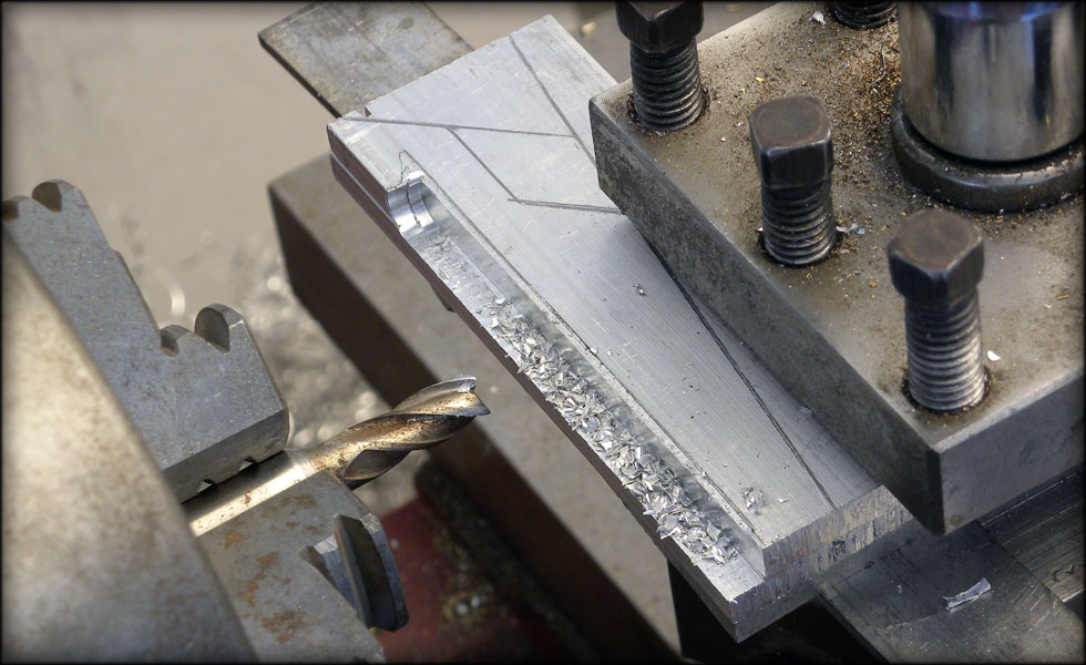
I found that using my dremel and cutoff wheel is the easiest, fastest way to cut these slots. One cut at the top of the hole, one at the bottom. If I had a milling machine this would be worlds easier, and more consistent, but I don't have a mill, so I have to do the best I can with what I have.
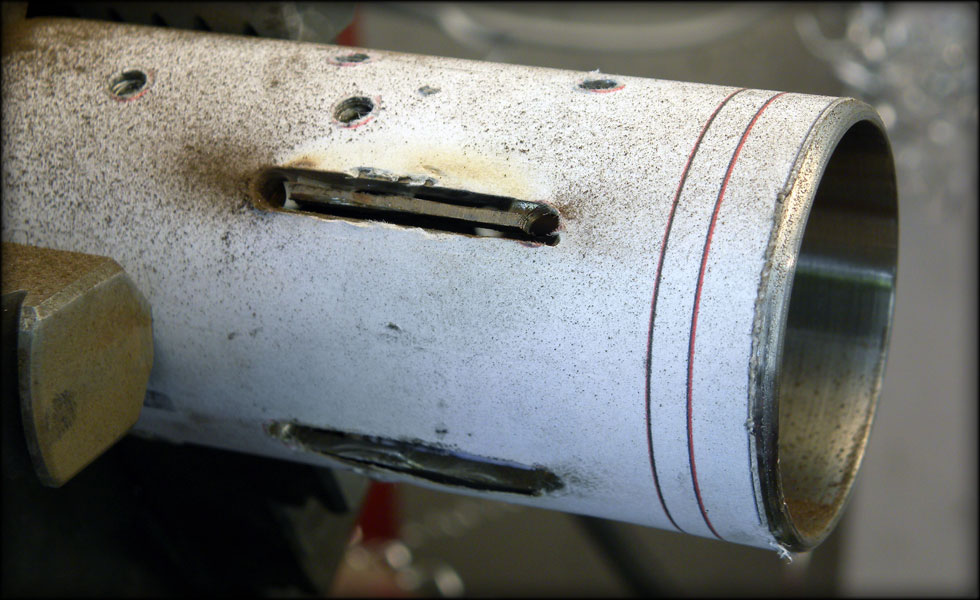
As you can see, the dremel cutoff wheel approach technically works, but leaves uneven results. I will have to bring some stainless tubing out to the ranch and use the big mill back home for this piece, but for now, I have this to think on.
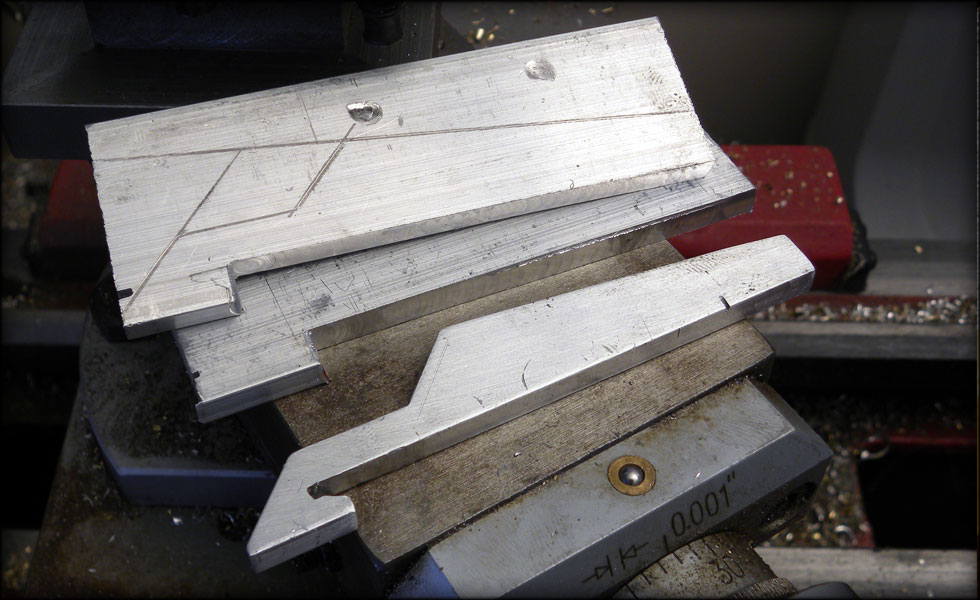
Three sets of three slots, and a groove at the back. Not terrible, but not up to my standards. I will re do this piece, and make two copies once I get time on the mill back at the ranch. I may go back out and enlarge the slots some to make them all more even, but I will most likely leave this piece alone and move on to a replacement.
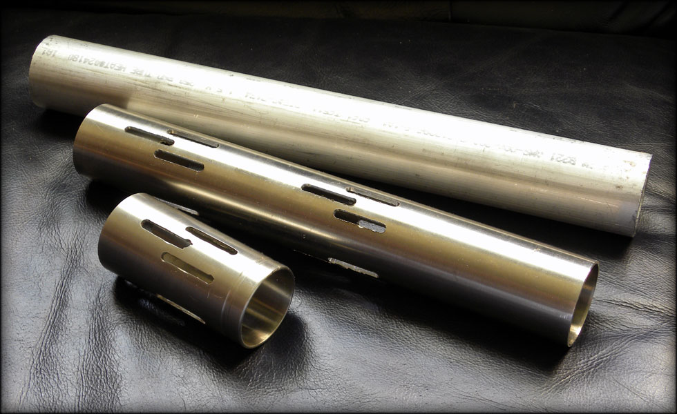
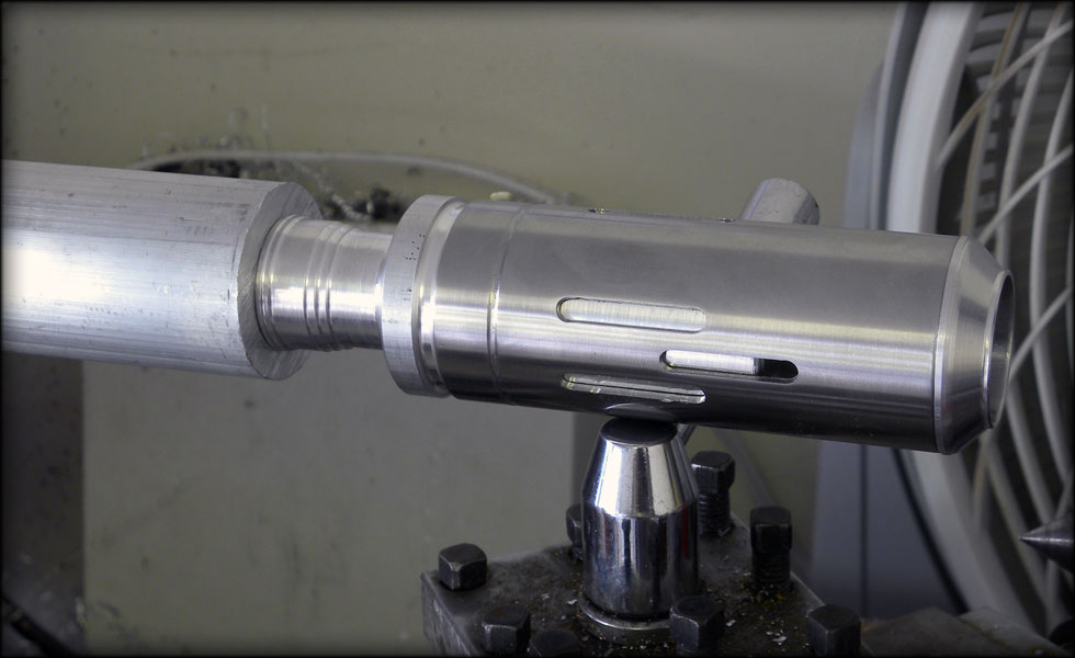
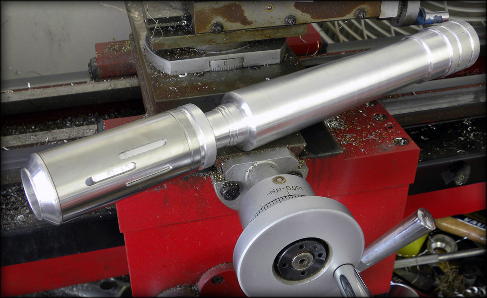
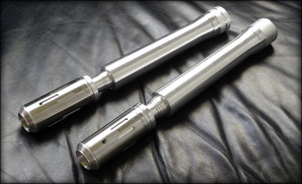
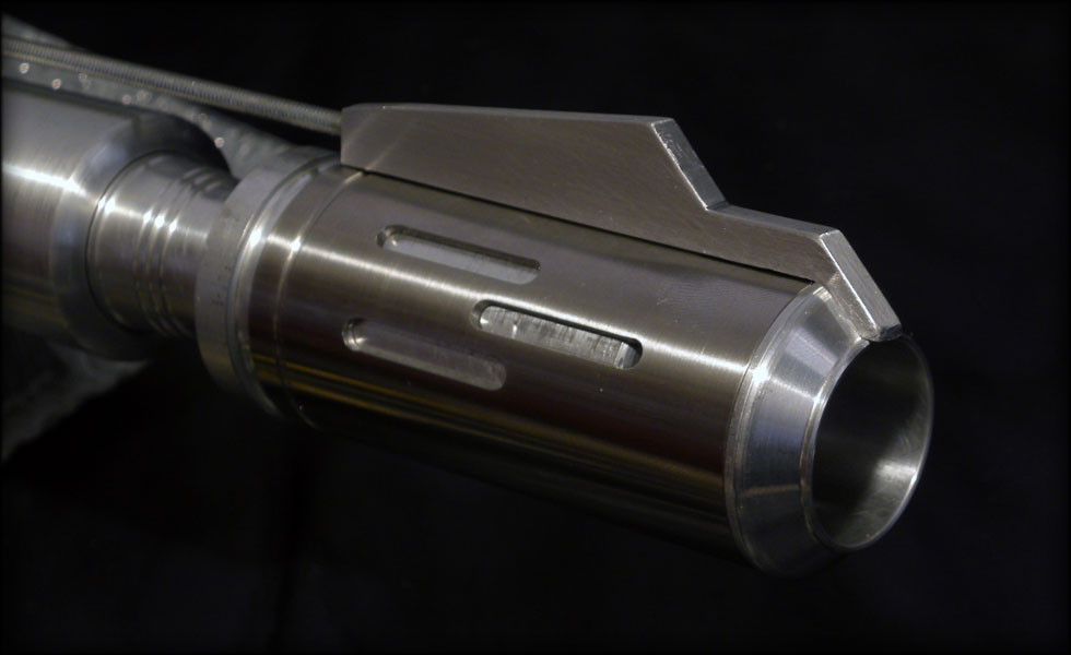
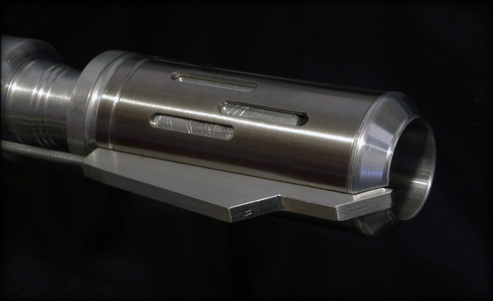
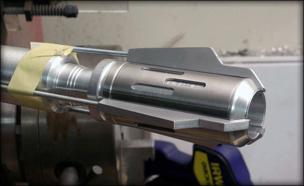
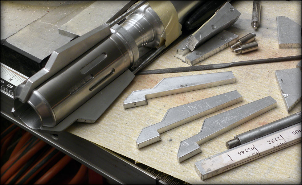
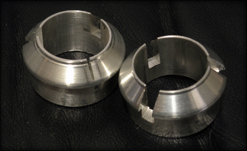
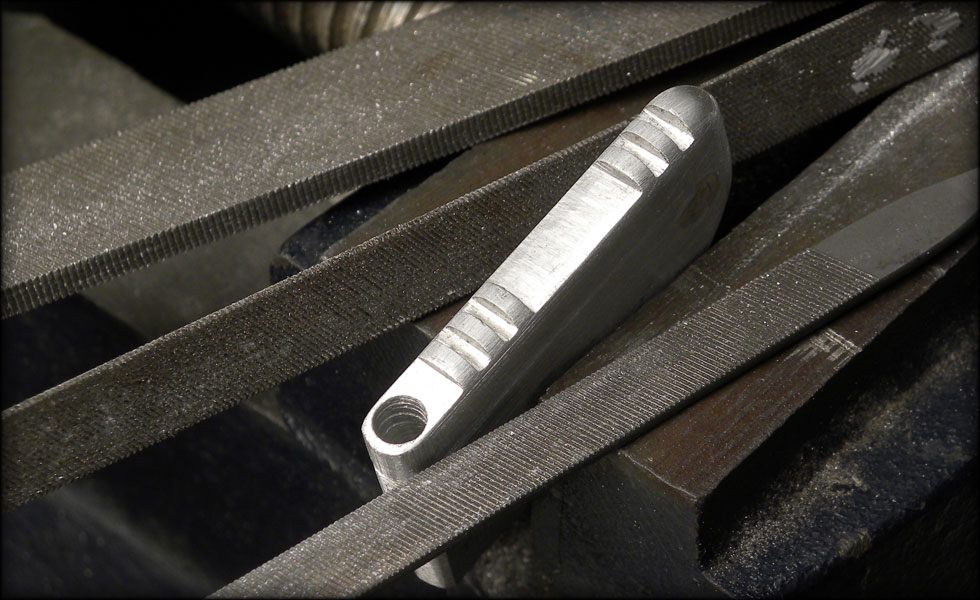
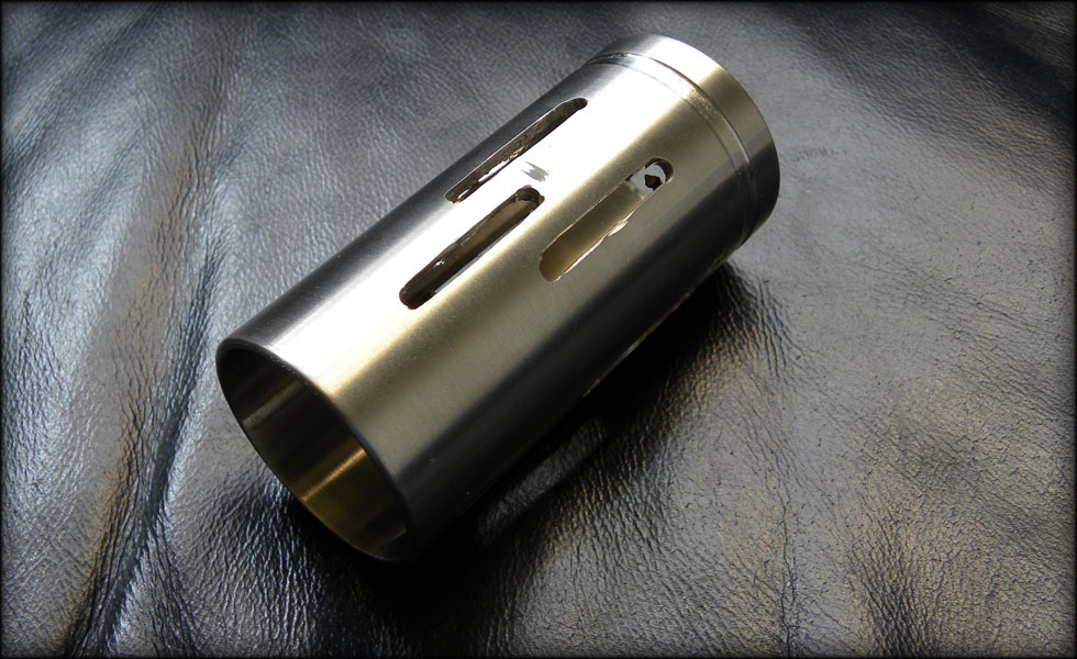
Here I had used a mill to cut my slots more accurately, straighter. The edges are kind of rough, I'll sand those out on the lathe. Once those are clean, I'll cut it in two so I have two emitter cans.
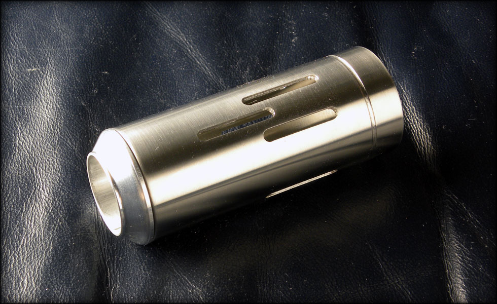
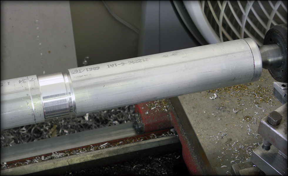
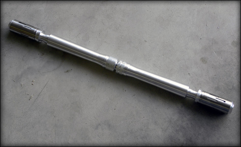
One end cap installed, I will have to shorten the emitter can a bit to the right length, but it's getting close to good.
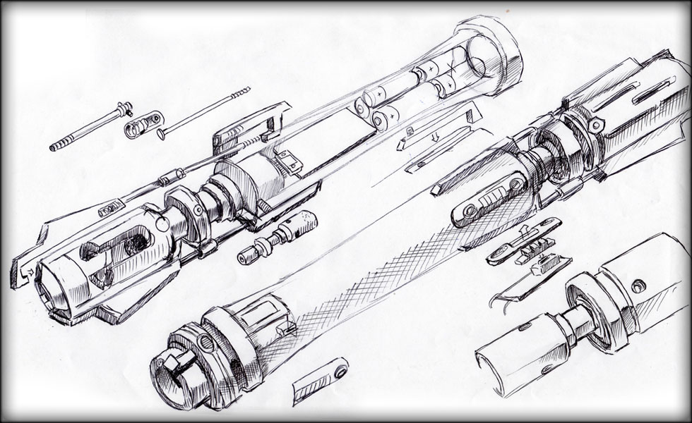
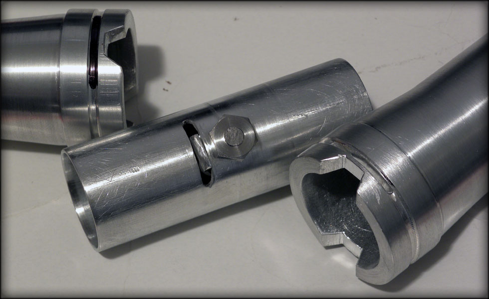
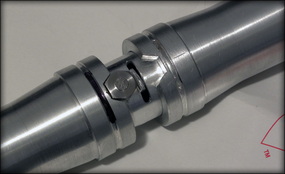
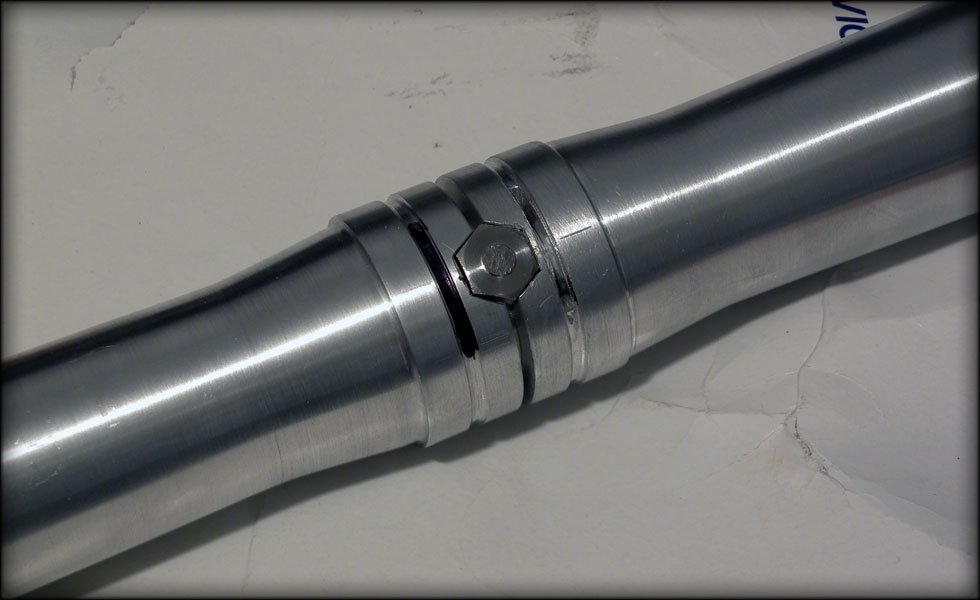
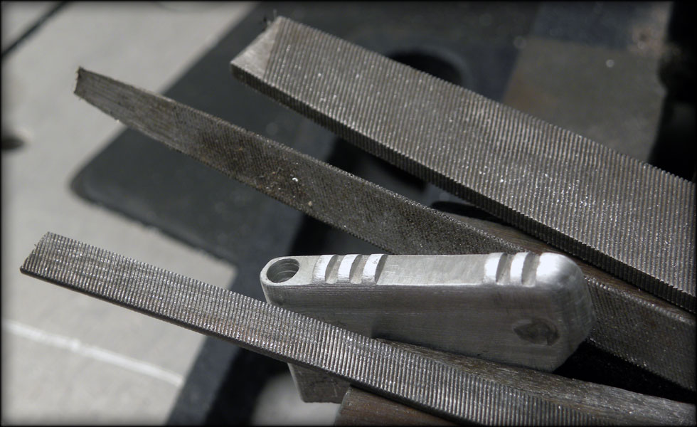
Here's a quick sketch I did showing how I think I am going to make the pieces to make this thing all come together.
Image property of BioWare
My wife wants me to make her the double bladed lightsaber that the Jedi Consular uses in BioWare's HOPE trailer for The Old Republic. This saber has been a challenge to begin, as I am not sure how to make the intricate details of the handle section. However, the rest of the saber isn't easy either. For instance, the emitters...
To start with, I decided to take some time and attempt to fashion the emitter ends from a section of scrap stainless steel tubing. I chose stainless over aluminum, because of the way the saber is rendered in the trailer, seems more fitting a finish in the long run than aluminum.
I took the screen capture above and blew it up in photoshop, duplicating it across the appropriate size paper to wrap around the diameter of the tubing.
This wraps around perfectly, and seems to look about right. However, I noticed it would be kind of hard to drill through that, so I used that image as a basis for a template that I printed out and replaced the old one with.
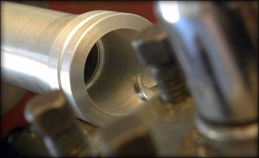
This marks my drill points, and groove for the back of the emitter.
Problem #1 - Holes drilled by hand on curved surfaces tend to wander the drill bit... a bit. Therefore making the holes not quite lined up perfectly. This is a problem, as I will have to connect the holes with slots to form the slots evident in the saber emitter, and they have to be straight, uniform, consistent and even. But, even though I know I will probably have to re do this part, I decide to forge ahead and see what I will learn by finishing it.
I found that using my dremel and cutoff wheel is the easiest, fastest way to cut these slots. One cut at the top of the hole, one at the bottom. If I had a milling machine this would be worlds easier, and more consistent, but I don't have a mill, so I have to do the best I can with what I have.
As you can see, the dremel cutoff wheel approach technically works, but leaves uneven results. I will have to bring some stainless tubing out to the ranch and use the big mill back home for this piece, but for now, I have this to think on.
Three sets of three slots, and a groove at the back. Not terrible, but not up to my standards. I will re do this piece, and make two copies once I get time on the mill back at the ranch. I may go back out and enlarge the slots some to make them all more even, but I will most likely leave this piece alone and move on to a replacement.
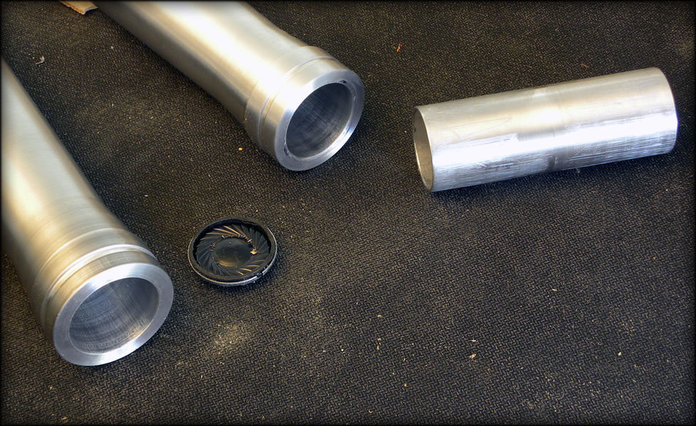
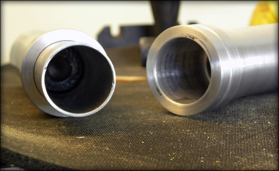
Here I had used a mill to cut my slots more accurately, straighter. The edges are kind of rough, I'll sand those out on the lathe. Once those are clean, I'll cut it in two so I have two emitter cans.
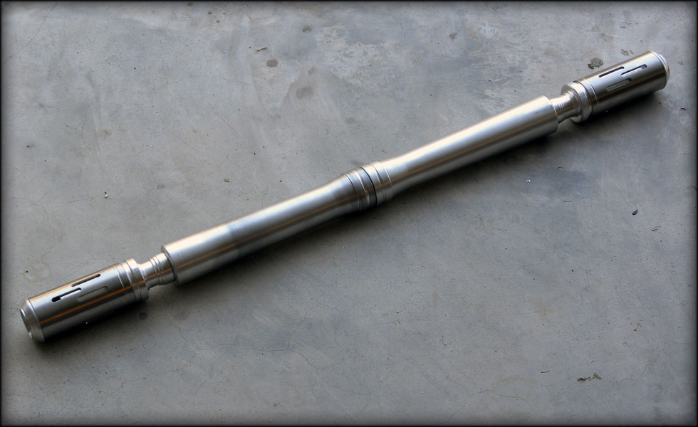
One end cap installed, I will have to shorten the emitter can a bit to the right length, but it's getting close to good.
Here's a quick sketch I did showing how I think I am going to make the pieces to make this thing all come together.