Obi-Wan ANH Sabre - Fully Self-Made!

Rastafun

New Member
Hi everyone, long time lurker, first time poster.

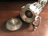
I've always coveted Obi-Wan's lightsaber, and after making a couple of ROTJ Luke sabres I realised it was within my grasp. After countless hours of scouring for every measurement and detail I could find, I spent the past few days out in my shop making this beaut

IMG_0991.JPG
IMG_0990.JPG

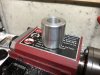
And here it is all broken down. I wanted to replicate the parts rather than the whole, I guess it just seemed like it would be more fulfilling.

IMG_0993.JPG

The only parts I didn't machine myself are the threaded rod and bubble strip (though I did consider it :rolleyes). The whole thing is 6061 alu, since that's what I had on hand, and the clamp is just some 22 gauge steel. I don't own a mill, so the pommel was a right pain to make. I bolted an angle plate to my cross-slide and the compound to the plate. I don't have any good way of mounting anything with it set up like that, so I usually find a way to screw it on. Overall, I could sit here and point out the flaws all day, but I'm thrilled to bits with it and that's all that matters.
 
Thanks for the kind words everyone! It always feels weird to share my projects with the world, so it means a lot to get positive feed back. I'll post some pictures of the individual parts and how I made them after I take some pictures.

amazing you made this without a mill. How were you able the make the grenade?
I bolted an angle plate to the cross slide and the grenade to the angle plate. This is the pommel, but it was the same idea: work the cross slide to mill the channel, loosen the bolt and turn 60º and repeat.

IMG_0962.JPGIMG_0963.JPG


Nice work. That looks great. Any progress pics? I always like to see how things are made.
Unfortunately, I didn't think to take many pictures. The ones above and below are all I got. I have a ROTJ Luke that I just finished, and I'm about to make an album of that! I'll also be making another one of these in the next couple of months, and I'll be sure to document it.

This is the inside of the emitter/balance pipe. I put the piece on the round stock in the vice, drilled a dimple, and rotated. I then used the more steady vice to drill all the holes through. I re-turned the surface of this part after this picture was taken to get a more accurate profile, since the single 30º chamfer isn't even close to correct.
IMG_0875.JPGIMG_0876.JPGIMG_0874.JPG


Without a mill?

Most impressive, someone has taught you well.
Thanks! Aside from This Old Tony on YouTube, I'm all self-taught :D
 
Starting from the bottom, the pommel is two parts: the main body, and a screw-on cap. The poor lighting and dark surface really accentuate the scratches and make the whole thing look dull, when in reality it's very reflective and the scratches aren't noticeable :unsure. I turned the profile of the pommel and then mounted it for milling (pictures above). I cut one face of each cube, turned it 60º, and repeated. Then, adjust the position and repeat until all faces are cut (left side, right side, middle). I was able to come up with a pretty good profile, but there's still a lot of guesswork. Scale the template I made to have a 49.5mm OD if you want to make your own. Also, note the bite taken out under the d-ring. The retaining nut wasn't tight enough...
s12.JPGScreen Shot 2018-05-21 at 22.25.40.png

Next up, the booster. Good from far but far from good, IMO! I don't have the tooling to generate the right profile, so I just had to settle for round. I planed to use some oversized stock, drill just inside the OD, and cut back to reveal teeth, but I didn't have anything big enough on hand. So, I just used what I had and "drilled" it with an end mill. Boy, was that a mistake. It looks alright painted and in context, but it's definitely the worst of the parts.
1.JPGs5.JPGScreen Shot 2018-05-21 at 22.24.24.png

The clamp was probably the easiest part of the build, since official plans exist for it. The plans were a little weird, so I resized them to be printed on 8.5x11 paper. I had some 22ga steel that I used. To form it, all I used was a file, a needle file, and a vice. By figuring out the order to do the bends and using the files as spacers, it's dead simple to make yourself. I tried cutting out the cosmetic slots with a dremel, but my cutoff wheel was too big for the smaller squares. I used some small pieces of aluminium for the blocks, and the pins I just turned from some small steel bars I had. If anyone wants more detail on how to make their own clamps (all I could find online was people saying you can't do it at home), I'd be happy to put together a short video.
s14.JPGs15.JPGs2.JPGs3.JPGView attachment graflex.png
 

Attachments

  • s1.JPG
    s1.JPG
    1.9 MB · Views: 150
  • 3.JPG
    3.JPG
    1.9 MB · Views: 162
Last edited:
For the grenade, I was able to locate some decent plans by an M. H. Taylor and an image of the neck section with dimensions. The way I cut the wind vane and the channels in the grenade are essentially the same as how I did the emitter. I could have made the wind vane more accurate, but I forwent accuracy in favour of not having to do any more milling with that awful setup. Also, the most astute among you may notice that the grenade has clockwise threads and the neck has counter-clockwise threads. Yup. I was able to correct the threads on the neck enough to get them to screw together (sort of), but I'm still pretty disappointed in my stupidity.
s6.JPGs7.JPG9.JPG

Finally, we have the emitter. Considering how little I had to go on, I think I did a pretty good job. There are some corrections I need to make to the inner piece, but I'm not going to bother for now. I did my best to capture the weird recess and chamfer and it doesn't look bad at all IMO. the OD of the top is undersized by a couple of millimetres, but I wanted to just use what I had for this project. I showed how I did the holes in my post above. The gist of it is mounting the piece in a drill press where it can easily be rotated without any x/y translation.
s9.JPGs10.JPGs11.JPG
 
This thread is more than 5 years old.

Your message may be considered spam for the following reasons:

  1. This thread hasn't been active in some time. A new post in this thread might not contribute constructively to this discussion after so long.
If you wish to reply despite these issues, check the box below before replying.
Be aware that malicious compliance may result in more severe penalties.
Back
Top