BTTF Time Circuits Display Wall Clock

JakeConhale

New Member
My next project is a wall clock recreation of the time circuits from back to the future as a wall clock, designed to both be aesthetically pleasing and functional.

Part of this is admittedly inspired by the post on the adafruit website: https://blog.adafruit.com/2012/07/0...spired-time-circuit-clock-with-adafruit-gear/
as well as by another person's pet project: http://www.partsnotincluded.com/projects/time-circuits/

That second site is worth a read, the author goes into lovely detail reverse engineering the original design and how he goes about his own recreation.

While I'm inspired by both, this is ultimately my own design. Not entirely sure how I'm going to make the exterior, but I anticipate spending more time on the circuitry and programming for now.

First entry: functionality.

I plan on including the following functions in my wall clock, presented roughly in order of priority/desireability:
  • Current (CURR) time with battery backup, accomodating leap years
  • Ability to manually set Destination (DEST) time as in the movie, as well as the Last Time Departed (PAST) time
  • Controllable brightness
  • 12/24hr mode select
  • DST mode select
  • LED color select
  • Secondary timezone - can select either PAST or DEST time field for display.
  • Stop watch, both count up and count down functions
  • Stop watch lap feature
  • Alarm clock
A bit of a list, but nothing too out there, many redundant functions. Not sure what else one could do with a wall clock.

The LED color select refers to how the actual prop differed from what was desired.
Time_Circuits_BTTF.png

You can see that the DEST AM/PM and colon lights are yellow rather than red. In the film, one can attribute that to Doc Brown simply not having the parts on hand.

All this will be controlled by an Arduino Uno and hopefully I'm not going to overload the board! My layout won't be perfect, but that's life.
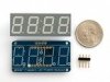
 
Second Entry: Design layout.

First things first, while I want to emulate the display as closely as possible, practicality demands adaptability. Mainly, I'm not eager to have to solder and control over a hundred different display character pins and printing my own circuit board was expensive, so I defaulted to these:

880-01.jpg

A group of four characters with a custom made I2C backpack from Adafruit available in both 7-segment and 14 segment displays in red, yellow, and green (after a fashion). I'm only using the 7 character display as the 14 character display lacks an internal colon and I wasn't sure how to satisfactorily link the displays to the backpack using wires leaving space for colon LEDs. I could use the 7-segment for the year counter, but I enjoy having the additional versatility in light of the other planned features.

This way, I can control everything easily and reuse code. Two problems: the first is that while the site offers "green" versions of both the 7 and 14 segment displays, I find it incorrectly listed as they're rather different shades. The site also offers a "yellow-green" version of the 14-segment displays which does match the 7-segment display. Annoying, but not too bad. The second is that these displays only come in four character groups, either one 4-character display or two 2-character displays placed adjacent. Looking back at the original prop, one will notice different widths, from 2 to 4 characters.

So, my plan is to cover the unused characters with the front panel, effectively hiding the characters from view.

layout.jpg
Here's a general overview of the planned layout. Sorry I didn't have time to draw it to scale and only minimally painted it... ;) The blue characters would be covered by the front face. The whites are the 14-segment displays, the peach colored ones are the 7-segment displays, and the colons are implemented using 5mm RGB LEDs. In the film, according to the parts not included website I listed earlier, the LEDs are actually 3mm, but I couldn't figure out a way to dim the LEDs effectively. I was working through an idea of having each LED on a separate pin connected to a common cathode pulse-width modulated pin to adjust the voltage, but I couldn't get the design to work, so I found an alternative. Also, in the film, the keypad is aligned with the left edge, but I'm concerned about balance and usability - I don't want to be biased towards left handed vs right hand users. I'm still considering mounting the keypad on either the left or the right side of the main display, which would be biased, but might be prettier than having it hang like a tetris block right there.

Something I didn't realize until just recently was that the film keypad differed from how I imagined. I had always thought it was five square, backlit buttons in various colors and we only saw the bottom button being used to enter the destination date. Upon review, the prop is actually four square LEDs (red, yellow, green, and white) with a black button on the bottom.

(This simplicity does, however, help explain how Biff was able to handle the time machine in BTTF II, as it would be hard for even an idiot like himself to go wrong with a numeric keypad and a single commit button).

So, for now I am going to use five 16mm backlit buttons for the side lights, as they look appropriate and add additional functionality in a non-invasive way.

The only aspect I'm really disappointed with is the keypad. I was initially considering using a payphone style keypad, which would look cool and fit in with the idea that Doc Brown had salvaged it to make the interface, but the only supplier I could find listed such for $40.00, whereas a smaller matrix encoded keypad was available at 1/6th the cost. Tough choice. The resulting keypad is a little smaller than it should be and it includes telephone style * and # keys, but, again, it adds functionality and who is really going to call me out on that aspect?
 

Attachments

  • 880-01.jpg
    880-01.jpg
    4.8 KB · Views: 912
Next installment: Power issues.

Here are two images showing my current set up, designed to test basic functionality in providing different but concurrent values to the different displays using I2C addresses and a 3-to-8 decoder chip. The 7-segment displays have the exact same address, but the 3-to-8 decoder chip is suppressing the I2C clock signal so only one display is actually listening at any given time. The second picture is in the dark to better illustrate the color issue. The two left most green alphanumerics and the green digit display are both advertised as "green", while the upper right alphanumeric is advertised as "yellow-green". Irritating that they didn't use the same terminology for the same wavelengths, but I'm just glad I didn't buy all three "Green" displays outright, just a pair to test the I2C addressing function. Really liked the "Green" alphanumerics, really intense forest green color. No, I'm not bitter, why do you ask?

20180218_Display_light.jpg20180218_Display_dark.jpg

I did encounter an unexpected issue, when I connected as few as two of these displays and ran them simultaneously, the characters would pulse. As in, from either right-to-left or left-to-right, the characters would noticeably dim and grow brighter. This confused/concerned me so I went to the adafruit forums and asked. Based on their response, I believe it's caused by my microcontroller providing insufficient power and the multiplexed displays having slightly different timing, so different characters would be lit at any particular time. Display 1 character 1 may be initially synched with Display 2 character 3, then drift to be synched with Display 2 character 4, and because the different characters use different segments, the power gets distributed differently and you get different intensities.

Long story short: my microcontroller isn't providing enough juice. Sigh, if only one could just walk into a store and pick up some plutonium, but alas, maybe in 30 years. The specs state that it can output a max of +5V at 500mA, while my current setup could desire as much as 1,260 mA (assuming 20mA per segment, three 14-segment and three 7-segments, not counting decimals or colons). And this isn't the full setup.

Wow, that's heavy....

Worst case amperage at +5V: ((14*3+7)*3)*20mA = 2,940 mA, and that's not counting the amperage from the lit pushbuttons, the I2C port expander, the 3-to-8 decoder, the backpacks, the real-time clock.... Granted, I don't expect it to ever actually NEED max power requirements, after all the displays are plenty bright with 5/12ths the max current draw, but want to do it as cleanly as possible.

So, I figured, I can just get a higher Amperage power supply, I'm running the microcontroller off of USB after all, and that only uses 5V as does everything else in my project.... but it turns out the microcontroller only accepts +5V through the USB cable, the dedicated power jack or Vin port each call for 7-12 volts. Not sure why. Also, I don't recall seeing a 2.1mm jack to USB converter, so I'm guessing there's probably a good reason for that and I shouldn't go cutting a USB cable apart to splice it together. I want to use the dedicated power jack as it's described having a voltage regulator, unlike the Vin pin, and I don't want to burn out my board.

Alright, so, having graduated college with a degree related to electrical engineering, I went back and came up with the voltage divider circuit. Using 4 resistors of the same voltage, two in parallel with two in series (2-1-1), I could easily drop 12V down to 4.8V before the last resistor and everyone's happy. Until a coworker reminded me that resistors have max dissipation values. I did the math. 3A at 5V = 15 watts while my resistors are designated at 1/4 watt dissipation.

Great Scott!

I don't know what happens when you put 60x the power through a resistor as it is rated, does it just stop working, does it melt/smoke/catch fire? I don't want to know, so I needed to find an alternative. I considered having multiple power jacks, one for the microcontroller and one for the circuitry, but I was terrified of accidentally confusing the two ports. Also considered using a power jack for the circuitry and a USB converter for the microcontroller, but I hated that as I wanted to be able to interface with the microcontroller independently. (As well as having to use 2 outlets to power ONE clock)

I looked into larger resistors or possibly using more resistors in a chain to distribute the wattage, but eventually found a UBEC DC/DC step down converter that would take various values such as +9V 2A and convert it cleanly into +5V ~3A. The +9V 2A power supply would also cleanly power the microcontroller and leave the USB port free. Wire the jack into the controller in parallel to the circuitry. The description does state the UBEC gets a little toasty at 3A so I am planning on side vent holes to allow airflow. Or, I suppose, I could use other converters for, say, 1 A and then provide a dedicated UBEC per display row, to separate the components into 1A chunks.

It's listed here: https://www.adafruit.com/product/1385

The reason why I went into such detail here is that I am worried there's another detail I've missed, like I need to somehow up the resistance on the microcontroller to prevent all the current from flowing through it rather than the circuitry. Or that I'll blow out one of my chips like the 3-to-8 decoder and I'd love to have someone alert me before I destroy anything. If anyone has any concerns, power-wise, I would greatly appreciate it!

Otherwise, I'm just about ready to order the remaining components. I suspect that's going to be the easy part compared to the coding half of this project...
 
Time for an update! Been a little while, guess you can say I've been a slacker...

So, a few weeks back I was planning on traveling and then something called a "bomb cyclone" hit and my flight got cancelled. Bummer, but on the upside I was able to use the refund to buy virtually all of the remaining parts! Now I just need to integrate them.
Setup_with_LEDs_piezo.jpg
This first picture shows my setup with the addition of two RGB LEDs and the piezo speaker. I've been able to get both to work, just need to integrate them into the project. The LEDs represent the AM and PM lights on the display which, quite frankly, I'm having a hard time keeping from locking the display in 24-hour mode and making these lights BC/AD indicators. Chalk it up to Doc Brown not fully implementing the design in the prototype. You may note the DEST red display showing only underlines, that's a small alteration I've made to help with the data entry. Each time you push a button, the corresponding digit is filled in while blank digits are marked with the underline, so you don't have to worry "wait, did I miss a digit?".

The LEDs work and I have been able to distinguish different lighting patterns on each. I was thinking of color-matching the LEDs to the yellow-green of the right displays vs the green of the left, but find I have a hard time distinguishing yellow-green from yellow, so lets go with the most distinct. The LEDs can be dimmed so I can adjust the brightness as needed, at least for the clock portion. Indeed, they NEED to be dimmed, as they are rather blinding at full intensity.
Keypad_layout.jpg

Here you see the keypad and light up buttons integrated into a piece of wood. Someone at work has been showing off a 3D printed, two part keyboard they made with a backing of laser-cut acrylic, looking to see if I could have this and the display rows cut in the same fashion rather than carving them out of wood. I was surprised by how large the keypad panel was and am likely to put the keypad in line with the clock on the left hand side, rather than beneath the clock as it's so large, unless the clock turns out to be too wide that way... ugh. I bought a blue button as well in case I wanted to replace one of the two whites. I've decided to use the # key as a cancel button, to abort the input string.

A few issues have cropped up, though. I had planned on dimming the keypad buttons in line with the display using 5 of the 6 PWM ports on the microcontroller. However, the Tone() function needed to generate sound from the piezo is noted in the documentation to interfere with 2 of those PWM ports, meaning I could only dim 4 of them or possibly try to run two off the same LED signal, but that would mean I wouldn't haven full individual control of the button lights.

Another, admittedly small, issue deals with the keypad. After reviewing footage of the film, I noticed the keypad buttons made telephone sounding beeps, which would make sense as some sort of industry standard, so I looked into the precise frequency. Turns out the buttons use two different sounds to denote an XY coordinate system. (#1 is row 1, column 1; #8 is row 3, column 2, etc). Guess that explains why telephone tones always sounded so discordant to me. My solution, assuming I don't scrap the piezo due to the PWM issue, would be to simply map the buttons to specific notes in the key of C. If I scrap the piezo, I also end up scrapping the alarm clock feature which isn't that vital to me but would be a nice to have.

Otherwise, I've been focusing on the code. I've got the clock display implemented, 12/24 hour time, alternate timezones vs static time, the colons to cycle up on the second and down on the half second, and looking into how to code the other buttons.

In the film, the colons always blinked, on and off at half-second intervals, but I was considering changing that. Say you had the DESTINATION time set as a different timezone (say London), how to differentiate that from a static entry time? Well, what if the colons blinked on the timezone, but were solid on static entries? There's no real benefit to having the colons blink on what would otherwise be static displays...
20180303_204947.jpg
This last image is a preliminary wiring diagram. The actual perfboard layout is still in flux. I replaced my I2C expander chip (MCP23017) with a smaller one (MCP23008) but still can't squeeze everything into this 30 row proto-perf board I have. (It's a perfboard set up in the style of a protoboard, for ease of transference). guess I'll have to use two. The five colored circles are the buttons, the lower red thing is the piezo, the blue circle is the clock, and the red/yellow/green rectangles are stand ins for each display row, as seen in the insert on the upper right. The insert has the phased colors to indicate all three rows are wired identically, the only real difference being that the LEDs are wired in series top to bottom (red, then green, then yellow) so they only use one pin. One thing that's rather nice is that I can separate the keypad and the display sections on different sides of the microcontroller.

(Side note: I have GOT to find something other than Microsoft Word to use to make these images!)

Still finalizing chassis designs, think I'll go with a hinged back for ease of access rather than screwing it in, but still working it out.
 
Another update.

I just implemented the sound for the keypad, giving each key a tone starting at G5 and ascending. I have to resist playing Ode to Joy (or maybe Johnny B Goode?) with the keys. Hadn't expected the common ground to interfere with the piezo, guess this means I'll have to dedicate a ground pin to the piezo if I want it to be silent rather than constantly vibrating.

A thought occurred to me earlier. I was concerned the PWM function for the brightness would be overridden by the piezo's Tone() function, as they use the same timer. Well, why would it? I'm not using the sound constantly, just for things such as key inputs and the alarm clock or a stop watch buzzer, otherwise no tone would be playing and thus the PWM on the two affected pins would be normal.

Experimentation required, of course - not sure what will happen to the button LED probably just flicker randomly, but seems logical. If you're using the keypad, you probably won't care about the button lights and if the alarm is sounding, you'll want to silence it.

.... oh god, now I'm seriously considering having it play the Battlestar Galactica theme as an easter egg...

BTW - would anyone know how to reverse engineer sound from an audio clip? Specifically, am curious if I can replicate the tone the prop makes when first turned on, but don't trust my ears and curious if anyone knows another way.
 
And... I'm back, from the past to post in the future and.... not sure where I'm going with this.

Still, the clock is pretty much functional! Have a look:
20180630_version1.0.jpg

Ain't she a beaut? That's her in Stopwatch mode, as indicated by the STP and UP in the Destination display, for counting up. Haven't implemented the Countdown timer or the alarm clock, but everything else is pretty much a go. I can set the time on all three displays, the PAST and DEST displays can show alternate time zones, all three have independent Daylight Saving modes for different areas, one can configure the DEST LEDs to be either red or yellow, 16 configurable brightness settings, 12/24 hour modes, just about anything you could ASK for from a clock. The power circuit works as well, finally.

About 1100+ lines of code, all told.
Which isn't to say it hasn't had some issues. The blasted power circuit, for one. It comes in at the bottom and is split to the microcontroller and through a converter to the rest of the board. Took me a little while to realize that it was causing the chronodot time keeper to drift, by as much as 30 minutes within 24 hours! Also, the neopixels (the multi-colored LEDs I use for the colons) were flickering something aweful, possibly from the Alphanumerics, so now the chronodot and the LEDs are powered off the microcontroller.

Another problem reared it's ugly head with the lightup buttons. The Arduino Uno has 6 PWM ports, but 2 of those are on the same circuit as the Piezo timer, so if those pins are at anything other than full brightness, a call to the piezo causes the lights to flash at full power. Annoying. Either I have to keep them at full brightness or I'm thinking I could split one of the pins for the two white buttons. At half the current they'd be dimmer than the red-yellow-green, but it'd be consistent and look *intentional*, which is my watch-word. Be canon, be non-canon, just make it look like it's meant to be that way.
The problem is, unfortunately, is that now that I've just about finished the code, I have to get started on the chassis. Haven't really worked out a design yet, not even sure if I want the rows to be tiered or in-line, but I'll figure something out.

And I have GOT to make up my mind about the green row. As noted before, the only consistent greens I can find are yellow-green, rather than a sweet deep green that's only on the alphanumerics. I'm debating buying whites and see if I could put a translucent green film over them to get the designed color, but that'd be about $50 at least.

Also still considering the payphone keypad rather than that small black keypad. Would also run about $40. *shrug*

Really, though, those are small details, quibbles, personal preferences. Only one actual issue still resides in this thing - apparently it's not 2038 compliant. (Like Y2K, but with all unix systems rolling over sometime in 2038). frankly, though, I can just offset the time when that comes, if I still have this thing in 20 years, I'll be surprised. It's fun, but it's no heirloom.

Really, you gotta admire Doc Brown when he built that thing. You ever read about the history of time? Not the Stephen Hawking book, I mean date systems. You've got different calendars, sometimes entire months were skipped to recalibrate things, all that. Course, it was just a movie, but he seemed a pretty thorough guy.

Any suggestions on how to cut out the character windows in 1/32" wood? I'm guessing using an exacto knife isn't the preferred method.
 
To cut the panel from wood, I'd use a jigsaw. Mark out the areas to be cut, measure it again, check it a third time, then drill a hole with a bit whose diameter is as wide as the jigsaw blade.

Then carefully proceed to rough cut the shapes, following up the finer points with a coping saw and files.

If you have a router, use that in place of the drill and jigsaw.

If you can, make a template in steel, just to be safe.
 
Thanks, I'll have to look into that, not sure where I'd find anything to do with steel. Frankly, if I could cut steel, I'd use that for the front plate as it'd look real cool and just like the film. The wood is a next best thing.

So, I had a slow moment at work for once (been hell lately) and started thinking about the chassis. Came up with this diagram which I was able to print out life-size on an 11x17 sheet of paper.
Initial_chassis_design.jpg
The diagram shows a quarter inch frame on the outside, but I'm looking to bump that to half inch on at least the sides, if not the top and bottom as well. Plan on using some #6-32 brass screw inserts embedded in the sides (and possibly top and bottom) to screw on the back plate, which would also be the mounting plate. Here's hoping half inch is thick enough to handle those inserts! The front could be screwed on, but would likely just be glued/nailed on. The displays would sit flush with the front panel through windows to help align them, the LEDs would be mounted to the cover plates.

Display_mount_side.jpg

Inside, I'd have the displays, circuit boards, and microcontroller mounted on an insert board using plastic standoffs. The displays would be on one side, everything else on the other, so that I wouldn't have to disassemble the whole thing to do any form of maintenance. The standoffs would allow for the pins to be wired up and allow the wires to be routed through various holes. That'd just leave the USB port, power jack, and the colored buttons/keypad as being mounted to the exterior, but with some sockets or something I should be able to have those be detachable. The board would have spacers on the edges to keep it stationary inside the chassis when closed up. I've run a test and the above image shows a couple displays mounted on standoffs, on the reverse side, they're attached by nuts and are very low profile.

Unless I can find some way to cut steel, everything will probably end up being made out of balsa plywood, with a few coats of paint to try to remove the wood grain. Considering trying to paint the section around the keypad green as in the film. Still, for now it's just arranging and rearranging parts in Microsoft word before I order things and start cutting. First will probably be some inserts and try to install those in a test piece of wood. Kinda worried about installing straight and I know I need to clamp it with two other pieces of wood to reduce risk of splitting, but any other tips/tricks?
 
Hello again. I've been busy with work but finally able to get back to this. I revisited the design of the front panel and came up with something a bit more compact. Here you go:
Front_face_1.PNG

The front face is a 1/4" piece of plywood sized to 6 inches by 12 inches along with 1/4" side panels, which is conveniently the size of plywood readily available at Michael's. I made components and sized them in Microsoft Word on an 11" x 17" piece of paper, so I can actually print it out at work and use as a template. The design is that the side walls bracket the front panel (to mimic the design of the movie time circuits) and the front panel screws into the top and bottom panel using brass screw inserts into 1/2" plywood. The sides also screw into the top and bottom, you just can't see that from this angle. I'm thinking I'll put in some decorative screws along the sides of the front face for appearances. The rear can also be 1/2", I just hope 1/4" for the sides and front is sufficiently strong.

The labels have been sourced, the height is straight off of an Ask-Me-Anything with a BTTF prop guy who said they were .218" and the font is Microgamma D Extended, which I'm told is the one they used in the film. All I need to do is figure out how to put it on stickers. I suppose I could just print, cut, and adhere using glu-stick...

You may note the shape of the AM/PM lights. When sizing this, I found the 5mm LEDs I planned to use, along with a mounting bezel, are just too darn large to fit in the panel, they overflow the height of the characters. I could try mounting the LEDs without the bevel, but I happened to remember a listing for rectangular RGB LEDs. 5mm x 2.5mm, they'd mimic the 3mm LEDs used on the original prop and, quite frankly, I think the rectangular look is more in keeping with the rest of the panel - the character segments, the overall shapes, etc. The LEDs and a driver circuit board should only set me back about $22 so I won't be crying to the poor house over this. Granted, if I hard wired the colors (e.g. only using the Green pin rather than the red, green, and blue pins for the Present Time display), it would simplify the design, but something about having full control of each LED appeals.

Each of the time displays would have a front panel covering it, using thin plywood or sheet metal and adhered by magnets, I think.

My current issue is that I'm having difficulty planning out the depth of the box. Want enough space to put the circuitry, but don't want to end up with several inches of unused depth in there, though I suppose I can just saw off the unneeded parts.

I'm heading home for Labor Day to see my family. My Dad's the one who made the wood chassis for my Star Trek 4B console so I'll definitely be picking his brain, might even see if I can get the boards cut while I'm up there. Wonder what the TSA would say if I tried to bring several pieces of plywood back in my carry-on...

Don't worry, I WILL get this done. Ain't no one gonna say I'm chicken or anything... I'll get it done or my name's Clint Eastwood.
 
...And I'm back. Sorry for the delay, it's almost like I faded out of existence for a moment there.

While I was home for the holidays, I worked with my Dad to make the rest of the box - the Top, Bottom, Left, Right, and Back. The back panel doesn't quite fit, but details. It's removable so I'll I can always run it on a belt sander sometime in the future. The wood has been spray painted with metallic aluminum spray paint. I want to add another coat or two, but it's currently near freezing and snowy outside, I've heard that's not the best spray painting weather. I suppose I can spray paint it any time as long as I cover everything up with painters tape, but it'd be much easier to spray now rather than later...

20190107_232043.jpg

Picture is showing my assembly of the box. Here I'm attaching the sides to the top, using the bottom as a guide and all my bottles of alcohol to keep things aligned. I heard on Canada's Worst Handyman that a box derives its strength from the back, not just the sides, they can fall in, so here I'm trying to add strength by using cut lengths of cove molding as corner braces. After The sides were glued on, I followed up with some brad nails and wood screws. Thing's solid now.

20190116_232007.jpg

The Front and Rear are attached using screws and thread inserts. This was more work than I expected. I had figured that if I was just careful and drilled the pilot holes through the lid into the edge of the Top/Bottom sides, the thread inserts and screws would go in smoothly. NOPE! The front panel was much smoother than the rear panel, I can tell you that! I made sure to always clamp the edges to ensure the inserts didn't break the sides of the top/bottom and some painters tape on the drill to help ensure the thread insert couldn't go too deep into the hole.

20190117_003009.jpg

And here she is with the buttons attached! One thing I was aware of but didn't account for was the bowing of the front panel. I thought I'd placed the screws wide enough to hold it flat but apparently not. Undecided if I want to add another screw in each corner, try to steam the board or otherwise flatten in, or leave as is. in a break from the film model, I decided to use thumb screws for easy access. As said earlier the front panel screws go in much easier, the top three and the left bottom go in smooth as silk, the middle bottom takes a iittle more work, and the bottom right, well, I'm surprised there's anything left for the screw to grab I had to adjust it so much.

Any tips on how to straighten the board? I tried wetting on the concave side and weighing it flat but as it was already painted, think the water didn't get in.

Some issues present themselves. My dad helpfully drilled pilot holes for the colon lights which I then tried to expand to fit my rectangular LEDs. Unfortunately, the holes are unevenly spaced and they didn't necessarily widen on a plumb line, some are noticeably tilted. I did plan on using 1/16" cover plates, so I might be able to hide the LED holes, but if I have to drill out more of it, not sure how to fit in the LEDs, is there some sort of putty I could use?

Next tasks:
  • Drill holes for the USB and power ports - this will be on the right hand side. Those should be easy as cake. I didn't want to put them on the back in case i wanted to put this on a shelf and press it against the wall.
  • Mount the LEDs
  • Mount the Keypad
  • Mount the displays
  • Mount the microcontroller and breadboard
  • Finalize wiring schematic
  • wire everything up
  • Test and adjust
  • Add soft feet so it won't scratch tables.
This thing is much larger than I expected, it's fully twice the depth I had originally planned. My original plan was to mount the breadboard and micro controller on the back panel, now I have enough room to mount them on the floor piece! So much for plans on wall mounting this beast, it's about 7" deep! Still, I have plans on where I can put it.

Kinda tempted to see about mounting the electronics to the top and see about using it as a sort of storage compartment, but probably won't.

Probably going to just glue in all the electronics, originally planned on screwing them in but not sure I have the tolerances for the screws to attach with the hand cut holes. Still, they just need to stay in, I shouldn't need too much glue and can just use an x-acto if i need to swap something out. My biggest fear at the moment is that I'll mount everything, wire it, test it, and find I got the displays all mixed around and have to extract and re-adhere.

If all goes well, I should be able to finish it this month, definitely no later than February!
 
Hello all. Project is... well, if not finished, at least at a state I'd be happy making no additional progress.

Finished it about a week or two ago, but work has been crazy so sorry to make you wait for the beautiful pics. Feast your eyes!

20190302_210001.jpg


Here she is in default mode with RED (as opposed to FILM) color for the Destination AM/PM lights. All in all, I'm happy with how it turned out.

Now, for some detail pics!

Showing off the power and USB jacks on the side: The screws for the USB connector were too short for the side panel but I was able to find some Imperial screws that just fit.
20190120_231119.jpg
My initial plan was to cover the unused digits with wooden cover panels, as seen below. Still considering doing it but she looks rather good without them!
20190121_221715.jpg
I may have gone overboard with the spray painting, gave the pieces a good 5+ coats of Rustoleum metallic finish aluminum spray paint. Probably should have sanded her down more before painting, but ultimately I think the wood grain is disguised as being brushed metal. Tried to protect my back deck with a roll of package shipping paper, but some still got around the edges.
20190127_140632.jpg
Some pics showing the internal wiring:
20190212_214256.jpg 20190302_210226.jpg 20190302_210856.jpg
I made sure to give the wires enough length that the front panel could fold down, wondering if I gave the wires too much length or if i just need better wire management systems. I soldered all the wires to the displays but connected the other end to a breadboard for debugging purposes. My intention was to solder everything to breadboard-style perfboard, but I'm not sure I want to take her apart again and solder 100+ wires when this works just fine! The second pic only shows the front partially opened as the last time things started sliding out of the breadboard, but the back is perfectly fine. You can't really see it, but I made sure that the chronodot, which as a coin battery as part of the time keeper, was on the end of the breadboard so I could easily access the battery if it needs replacement.

You can also see the screw inserts, those were "fun" to get in.

The displays are superglued against the front panel. The Arduino Uno that's the brains of the whole thing is mounted to the bottom using a protective case, just to make sure dust or whatever doesn't interfere with the board. Like Doc Brown, I want this thing lightning-durable!

20190302_210446.jpg
As you can see on the pic above, I added fuzzy feat so it won't scratch my furniture. You can allso see how the front panel is bowed outwards. I thought the thumbscrews would flatten it (and it does) but if I had to do this over again, I'd have put the screws at the outer edges rather than evenly spaced.

Things still to do:
  • Adjust the Daylight Savings Time to default off - it'll be wrong half the year either way, but feel that works better
  • Implement a count down timer as well as the count up timer. Not sure if I've posted a pic of that, will do if anyone wants to see it.
  • Implement an alarm clock
  • Give sounds to the side buttons, currently they're dead silent.
But all in all, those are minor things. She's beautiful, but not perfect.
  • The keypad really should be white if you're going for high visibility in a dark car. Just cannot see the black keypad.
  • The yellow side button isn't yellow. It photographs yellow, oddly, but in person its closer to gold or brown rather than say the yellow of the LAST TIME DEPARTED display.
  • The thumbscrews don't really work. I figured they'd work as a form of easy-access and they look nice, but they're smaller than I realized they'd be and a pain to turn. Still, that's why I put the USB jack on the side, so that I could make some adjustments without having to pop the hood.
I learned a lot from this project and had quite a bit of fun doing it. I hope my next project (thinking a HAL 9000 eye...) won't take quite so long.

Now, if you'll excuse me, I've got some family business to take care of. Let me just set the destination time....
20190302_212146.jpg


And away we go!
20190225_022640.jpg
 

Attachments

  • 20190302_205827.jpg
    20190302_205827.jpg
    1.2 MB · Views: 287
This thread is more than 5 years old.

Your message may be considered spam for the following reasons:

  1. This thread hasn't been active in some time. A new post in this thread might not contribute constructively to this discussion after so long.
If you wish to reply despite these issues, check the box below before replying.
Be aware that malicious compliance may result in more severe penalties.
Back
Top