jcgardea
Active Member
Someone asked me for help on the chest box lights, and I was already planning on uploading my WIP so here is this tutorial.
While I was doing my research to make my lights I found there is no definitive sequence for the lights since access to the real props is very hard, actual footage or reference is not very clear.
So I did my own analisys of the ESB movie going frame by frame, and the results you can see on this video:ESB LIGHT BOX SEQUENCE REVISITED
The chestbox on film appear to have 2 separate lights per slot, which means more combinations thus more complex sequence, if any.* I considered 1 fully lit slot only since that’s what almost all vendors do. I believe only Space-In-Vader at Vaderbase.com has a box with 2 lights per slot and is amazing but not cheap*(not for me at least).*
After doing my own set of lights electronics I can say it may be more pratical to*buy from Fettronics or any other vendor, because if you never have soldered electronics it can be a little hard and time consuming, and after buying tools and materials ... the total cost just about matches buying a ready one and the only savings are taxes and shipping. But the advantage is that you get to code your own custom sequences and the satisfaction of self-made lights.
What you will need is as follows:
Materials:
1 Arduino controller board. ( Adafruit Trinket or Trinket Pro.)
1 small rocker switch.
1 small push button
1 yard of red cable 24 or 26 ga.
1 yard of black cable 24 or 26 ga.
1/8", 1/4", 1/2" heat shrink tubing
1 9v battery. (a rechargable Lithium battery can be used as well , see Trinket documentation)
9 red high*luminosity leds
1 diffused red led (optional)
1 diffused blue led (optional)
3 resistors *60ohm (to be confirmed)
Solder and solder paste
(If you’re anything like me, buy x2 in case you screw up..)
Tools:
Soldering Iron for Electronics (static free)
Cable Snips
Helping hands
Rotary tool (Dremel or such)
So what I used is a little controller board from AdaFruit electronics called*Trinket which is arduino programable and ready to use, and is quite cheap (around $7 dlls). There is also a Trinket Pro which has more features, if you already know your way around electronics and arduino coding, give it a go perhaps you can integrate sound as well. (perhaps the respirator sound ... maybe?). You can find more about it here:Adafruit Trinket
One thing about the Trinket is it has only 3 analog pins that can be used with*PWM (Pulse With Modulation), which means they fade the light slowly on the leds. Those pins are numers 0, 1, 4. (*note:Trinket Pro has x2*PWM pins).
So those pins ; 0, 1, 4, will be the pins used for the slot lights.
Pin 3 will be the momentary push button to switch between sequences.
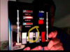
Pin 2 is optional for accesory lights, I use them to light up the blue and red acrylics slightly.
Pin BAT is for power or battery.
Pin Gnd is for Grounding the circuit.
And so, the diagram of the lights looks like this:

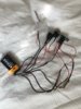
Now the slot leds I grouped them with the help of a pin board, and cut it with a rotary tool so to fix the resistor and have the leds evenly spaced. And because of all the grounding are* to be connected in order to close the circuit, I used a pin board again to connect them all together to try to keep the cables tidy. I tried to use as much shrink wrap as possible to protect the solders*and avoid the cables from breaking. I tell you more than 1 cable broke on me while soldering the others.
And this is what the completed lights rig looks like.


Now on to the sequence... The first sequence I defined is the "ESB Idle sequence" ; small pause between 6 and 7, and full pause in steps 8 and 10.

The second sequence I used is the "ESB Active sequence" ; with small pauses between 4 and 5, 6, and 7, 8 and 9, and full pause in steps 12 and 14.

Just for reference below are Fettronics and Anovos sequences.


Now to get the coding into the controller board, you will have to install the Arduino software, and download the Trinket software and Trinket firmware, connect the Trinket to your computer with a USB cable and upload the sketch (or code). Check the Trinket documentation for further indications on how to do so. Just download the sketch file, upload to the trinket and give it a run. Then you can customize it as you see fit.
*Note: I order to switch between sequences the pusht button must remain pressed thru the end of each cycle, so that the Trinket can read the button has been pushed. This is because I coded using the 'delay' command which does not allow the card to have any input until the delay command has finished. A more versatile way to code it is using 'time' commands which would allow the Trinket to read that the button is pressed at any time and switch sequences, but I found out about it after I was done and my programming abilities are not there yet.
Here is the arduino file:ESB_fade_w-button_rev1.1.ino
So here's a little demo of how my light setup is at the time.DIY Vader chestbox lights demo
Cheers!,
While I was doing my research to make my lights I found there is no definitive sequence for the lights since access to the real props is very hard, actual footage or reference is not very clear.
So I did my own analisys of the ESB movie going frame by frame, and the results you can see on this video:ESB LIGHT BOX SEQUENCE REVISITED
The chestbox on film appear to have 2 separate lights per slot, which means more combinations thus more complex sequence, if any.* I considered 1 fully lit slot only since that’s what almost all vendors do. I believe only Space-In-Vader at Vaderbase.com has a box with 2 lights per slot and is amazing but not cheap*(not for me at least).*
After doing my own set of lights electronics I can say it may be more pratical to*buy from Fettronics or any other vendor, because if you never have soldered electronics it can be a little hard and time consuming, and after buying tools and materials ... the total cost just about matches buying a ready one and the only savings are taxes and shipping. But the advantage is that you get to code your own custom sequences and the satisfaction of self-made lights.
What you will need is as follows:
Materials:
1 Arduino controller board. ( Adafruit Trinket or Trinket Pro.)
1 small rocker switch.
1 small push button
1 yard of red cable 24 or 26 ga.
1 yard of black cable 24 or 26 ga.
1/8", 1/4", 1/2" heat shrink tubing
1 9v battery. (a rechargable Lithium battery can be used as well , see Trinket documentation)
9 red high*luminosity leds
1 diffused red led (optional)
1 diffused blue led (optional)
3 resistors *60ohm (to be confirmed)
Solder and solder paste
(If you’re anything like me, buy x2 in case you screw up..)
Tools:
Soldering Iron for Electronics (static free)
Cable Snips
Helping hands
Rotary tool (Dremel or such)
So what I used is a little controller board from AdaFruit electronics called*Trinket which is arduino programable and ready to use, and is quite cheap (around $7 dlls). There is also a Trinket Pro which has more features, if you already know your way around electronics and arduino coding, give it a go perhaps you can integrate sound as well. (perhaps the respirator sound ... maybe?). You can find more about it here:Adafruit Trinket
One thing about the Trinket is it has only 3 analog pins that can be used with*PWM (Pulse With Modulation), which means they fade the light slowly on the leds. Those pins are numers 0, 1, 4. (*note:Trinket Pro has x2*PWM pins).
So those pins ; 0, 1, 4, will be the pins used for the slot lights.
Pin 3 will be the momentary push button to switch between sequences.
Pin 2 is optional for accesory lights, I use them to light up the blue and red acrylics slightly.
Pin BAT is for power or battery.
Pin Gnd is for Grounding the circuit.
And so, the diagram of the lights looks like this:
Now the slot leds I grouped them with the help of a pin board, and cut it with a rotary tool so to fix the resistor and have the leds evenly spaced. And because of all the grounding are* to be connected in order to close the circuit, I used a pin board again to connect them all together to try to keep the cables tidy. I tried to use as much shrink wrap as possible to protect the solders*and avoid the cables from breaking. I tell you more than 1 cable broke on me while soldering the others.
And this is what the completed lights rig looks like.
Now on to the sequence... The first sequence I defined is the "ESB Idle sequence" ; small pause between 6 and 7, and full pause in steps 8 and 10.
The second sequence I used is the "ESB Active sequence" ; with small pauses between 4 and 5, 6, and 7, 8 and 9, and full pause in steps 12 and 14.
Just for reference below are Fettronics and Anovos sequences.
Now to get the coding into the controller board, you will have to install the Arduino software, and download the Trinket software and Trinket firmware, connect the Trinket to your computer with a USB cable and upload the sketch (or code). Check the Trinket documentation for further indications on how to do so. Just download the sketch file, upload to the trinket and give it a run. Then you can customize it as you see fit.
*Note: I order to switch between sequences the pusht button must remain pressed thru the end of each cycle, so that the Trinket can read the button has been pushed. This is because I coded using the 'delay' command which does not allow the card to have any input until the delay command has finished. A more versatile way to code it is using 'time' commands which would allow the Trinket to read that the button is pressed at any time and switch sequences, but I found out about it after I was done and my programming abilities are not there yet.
Here is the arduino file:ESB_fade_w-button_rev1.1.ino
So here's a little demo of how my light setup is at the time.DIY Vader chestbox lights demo
Cheers!,
Last edited: