Vacuform C-3PO Head

Paul6700

Well-Known Member
RPF PREMIUM MEMBER
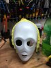
I picked up this vacuform kit over at the R2 Builders site and never built it. I believe it was made by Starbuckcylon. It has been kicking around my garage for about 3 years now and it is time to build it.

2015-08-24 20.30.38.jpg

Everything came with the kit, except for the four inch ABS slip fit connector which I plan to use for the neck.

The plan is make random colored protocol droid this is beat up, weathered, and looks like it was removed from a body. I also plan to make the eyes light up and maybe say a couple of phrases.

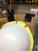
The problem with my kit is that the front and back shells do not fit very well together. Additionally the resin horseshoe is pretty badly warped. I was able to clamp the horseshoe between two boards to straighten it out, but it too did not fit the shells well.

2017-06-17 14.41.32.jpg

The back shell was even worse. I cut out everything that was supposed to be removed and I ended up removing the majority of the top of the back shell. I also ended up cutting up the horseshoe.

2017-06-17 15.06.36.jpg 2017-06-17 15.06.58.jpg 2017-06-17 15.48.04.jpg 2017-06-17 15.48.22.jpg


2017-06-17 15.48.32.jpg

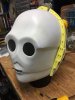
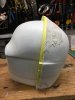
The two halves are attached to each other and there will be a lot of bondo to reshape the head.
 

Attachments

  • 2017-06-17 14.41.32.jpg
    2017-06-17 14.41.32.jpg
    904.8 KB · Views: 358
  • 2017-06-17 15.06.36.jpg
    2017-06-17 15.06.36.jpg
    772.6 KB · Views: 188
Started today by grinding down the extra material on the back detail. By grinding it down with a dremel, I was able to create a nice lip to make it easier to glue into place.

2017-06-17 16.10.18.jpg

I also attached the 4 inch ABS coupler with long screws through the back shell and the horseshoe. This allows the neck piece to pivot slightly.

2017-06-17 16.51.43.jpg 2017-06-17 16.51.54.jpg

I knew I would need to bondo the head, but I decided to use an epoxy putty first to build up the proper shape and then finish it with bondo. I also used it inside the head to back up the areas where I might sand through the shell. Drilling the holes in the top of the head gave the putty something to hold onto.

2017-06-20 18.32.05.jpg 2017-06-20 18.46.16.jpg 2017-06-20 18.46.33.jpg 2017-06-20 22.29.40.jpg

2017-06-20 22.56.02.jpg 2017-06-20 18.31.33.jpg 2017-06-20 18.31.39.jpg
 

Attachments

  • 2017-06-17 16.51.54.jpg
    2017-06-17 16.51.54.jpg
    831 KB · Views: 149
  • 2017-06-20 18.46.16.jpg
    2017-06-20 18.46.16.jpg
    906.1 KB · Views: 160
Made progress on the eyes tonight, but I forgot to take more pictures. Used the Dremel to clean up the eye openings and then painted everything silver.

2017-06-17 21.01.39.jpg

Since I am making a protocol droid other than C-3P0, I chose a white LED over the yellow ones. These are prewired 12 volt LEDs that I plan to wire to a switch that will be hidden in the neck opening.

2017-06-17 21.10.59.jpg

The wires are coiled and zip tied together with enough wire to run down to the neck.

2017-06-17 21.38.33.jpg
 
Went to Home Depot and bought a variety of plumbing fittings to create the neck. I want it to look like the neck could be slipped into the body of a protocol droid. Additionally, I need areas to put the switches, a sensor and batteries.

2017-06-21 18.39.19.jpg

I am using a reducer, piece of ABS pipe and the slip connector for under a sink. The pipe was cut to length and everything sanded. This is what it looks like assembled.

2017-06-21 18.40.05.jpg

I cut a piece of styrene to fit inside the cap to mount switches.

2017-06-21 18.38.45.jpg


Installed switches into the cover, one will power the sound system, one will power the eyes and the push button will allow me to play a sound on demand. The extra hole is for wires to hang down and to help disguise the very end of the neck.

2017-06-26 18.57.24.jpg


Here are the electronics and parts of the neck. I am going to use the Adafruit FX Soundboard to trigger the sounds (not pictured). It has an onboard amp and will hopefully be perfect for this project. To play sounds I will use the push button and a motion sensor connected directly to the sound board. There is a hole drilled in the pipe for the motion sensor. The speakers will be connected to the soundboard amp and are from an old laptop. The sound board needs 4 to 5 volts of power and the eyes need 12 volts, so there are two battery packs.

2017-06-26 19.01.56.jpg

Here is the assembled neck, it will slip into the 4inch ABS slip coupler perfectly.

2017-06-26 19.27.27.jpg
 
It is now time to shape the head and fill in with Bondo.

The process is simple, Apply, Sand, Paint and Repeat.

2017-07-01 11.51.42.jpg 2017-06-27 22.36.38.jpg 2017-06-27 22.36.48.jpg

Apply, Sand, Paint and Repeat
2017-07-02 18.31.43.jpg 2017-07-02 18.31.57.jpg 2017-07-02 18.32.59.jpg

2017-07-03 00.54.43.jpg 2017-07-03 00.54.57.jpg

Apply, Sand, Paint and Repeat

2017-07-16 15.44.01.jpg 2017-07-16 15.44.26.jpg

I tried to sharpen the lines of the face shell with each application. Eventually moved on to glazing putty and finer sandpaper.

2017-08-07 18.32.36.jpg 2017-08-07 18.33.22.jpg

Then a final coat of black paint.

2017-08-08 19.50.29.jpg 2017-08-08 19.50.44.jpg
 
I am really curious to see how a coat of gold spray paint ia going to look. Tje new formulas, even from the hrdwre stores, are said to be quite a step up in quality.
 
I am really curious to see how a coat of gold spray paint ia going to look. Tje new formulas, even from the hrdwre stores, are said to be quite a step up in quality.

I decided early on that I was going to do a different protocol droid head, other than gold. I am going to go for an old chipped up and weather beaten paint scheme.
 
Today I got a few odds and ends done. Soldered wires onto the ends of the small LED flashlight battery pack. This battery will be for the sound board.

2017-07-02 18.34.53.jpg

Earlier in the week, I built a battery box out of a Fatuba servo box to house the two battery packs.

2017-06-26 18.58.09.jpg

Drilled holes in the plastic for the wires and to mount a ground strip on top. Then painted the whole thing black.

2017-07-03 23.58.22.jpg 2017-07-03 23.59.17.jpg 2017-07-04 00.19.30.jpg

As soon as I receive the sound board, I will mount it along with the speakers on the back of this box.

Sanded the whole head one more time and sprayed it with aluminum colored spray paint. This will be the base color.

2017-08-09 14.41.50.jpg

Drilled out the botton of the top greeblie and glued on a 4-40 nut to match the screw that is mounted in the horseshoe.

2017-06-20 22.56.30.jpg

Test fit the greeblie to the head and reattached the neck to the head.

2017-08-09 14.52.19.jpg

Also, marked up where I will need to hollow the back of both ear thingies. I do not think I will need to access these screws again, so will likely just glue these in place.

2017-08-09 15.20.26.jpg 2017-08-09 15.20.34.jpg
 
Received the sound FX board from Adafruit today and was able to solder it the header pins and terminal screws into place. Learned more about soldering today, like use the breadboard to hold the pins straight while you solder. Here is a picture of the board connected to the 2 watt speakers and power through the switch. At this point I am abandoning the button for just the sensor to trigger the sounds.

2017-07-02 18.33.59.jpg

I completely forgot to take pictures of the sensor. It has three headers, ground, power, and signal. The signal wire is soldered to the center leg of the pulldown capacitor. This way the positive voltage from the sensor can be converted to 0 voltage and trigger the sound. I am surely not describing this completely. The Adafruit website was a wealth of knowledge, however this tidbit was hard to find so you do have to do some reading.

2017-08-15 19.32.08.jpg 2017-08-15 19.31.57.jpg

I glued the speakers to the battery box and connected everything. Also, I mounted the battery box to the neck.
 
Next up, is a very simple paintjob. The first color is aluminum color from a rattle can that was allowed to cure over a couple of days. Next I masked off everything I wanted to remain an aluminum finish and then airbrushed a matte blue acrylic paint over the main shell.

2017-08-09 18.51.56.jpg 2017-08-09 19.00.05a.jpg

Before I added anymore paint I wanted to get the eyes in place, so that they can be weathered along with the head.

2017-08-09 21.11.31.jpg

The acrylic paint is very easy to scrape off at this point, I wanted the paint to look worn and scratched up. I used a screw driver for some of it and my finger nail for other parts. I also used some light sandpaper for some areas to just rough up the surface.

2017-08-09 22.25.51.jpg 2017-08-09 22.26.00.jpg 2017-08-09 22.28.54.jpg

Then I thinned matte black and a green black with water and applied it as thin washes over all of the parts. I worked in small areas and would dab off the excess with a damp cloth. I would keep doing this until I liked the finish it was leaving behind.

2017-08-14 19.26.57.jpg 2017-08-14 19.27.17.jpg

Finally a few layers of tan acrylic paint to really make the surface look dirty.

2017-08-14 20.14.42.jpg

Now to allow everything to dry before I add the last details.
 
Finished up assembly and programed the board to play random quotes.

Glued the ear thingies into place with hot glue. I used hot glue just in case I need to remove them in the future to get the screws.

2017-08-14 22.22.10.jpg

Then connected the eye leads to the neck and slipped the neck into place. It is just a slip fit.

2017-08-15 19.29.35.jpg 2017-08-14 22.26.36.jpg

Here is the fully assembled head with working eyes and random quotes.

2017-08-14 22.41.29.jpg 2017-08-14 22.42.00.jpg 2017-08-14 22.42.24.jpg 2017-08-14 22.43.46.jpg

2017-08-14 22.42.56.jpg

Here is a quick video of what it looks like and you can here the random quotes.


The Adafruit FX Sound Board was super easy to program, you just need to use their naming system for the files. I used a free text to speech software with a UK female voice that allowed me to save the file as a wav file. Then I imported the wav files into Audacity and added an echo, then renamed each file and downloaded them directly to the board.

This was a fun build, I should maybe make the rest of it. My goal was to create a static prop that would sit on my desk and talk at me from time to time. Anyway, big thank you to everyone who liked what I did.
 
Last edited by a moderator:
Excellent work! I really like that you created your own dialog instead of using C3-PO clips. It makes it really stand out. Great work.
 
This thread is more than 6 years old.

Your message may be considered spam for the following reasons:

  1. This thread hasn't been active in some time. A new post in this thread might not contribute constructively to this discussion after so long.
If you wish to reply despite these issues, check the box below before replying.
Be aware that malicious compliance may result in more severe penalties.
Back
Top