ST:ENT Hand Scanner Help & Suggestions

So I've been printing the rest of the parts for tests. just the outside though..

Not too bad. The top isn't as curvy as the original prop, I personally like my version a little better. I think it fits the overall feel of the scanner better. I will adjust the edges to match the body tho. And I'll try to make one that is identical to the show prop too.

The side grips are also a little tough.. sketchup doesn't have a good Boolean tool like blender so I have to combine the bump to rounded edge by hand... tried a simpler version and it feels better in my hand but its not as accurate to the show...

Any thoughts on the overall look... like my version of the top?... suggestions, comments always welcome.

ENTSCN03.jpgENTSCN04.jpgENTSCN05.jpgENTSCN06.jpg
 
Looks good, nicely done.
I think I prefer the original shape of the top part of the scanner, but that could just be because I'm so used to seeing it from the show.

Good luck with the sanding/smoothing. As someone who makes a lot of 3D printed and laser cut props, the clean up can be the most tedious part of any build, but getting it right and putting in the hours pays off in the end.

Good luck, sir.
 
Last edited:
Looks good, nicely done.
I think I prefer the original shape of the top part of the scanner, but that could just be because I'm so used to seeing it from the show.

Thank you for kind words. So looking at it this morning, you're right ... I think the top part is too rectangular. Front on view it looks good, but at any angle it's too blocky. So I'll definitely be re-doing that part to match the show.
 
Been following this thread with interest. I too made the Enterprise Scanner along time ago (before 3D printing) and ''old school'' by hand.

I did not cast it out of resin, but instead used mostly styrene for the outside body so that it would be hollow for electronics (backlighting the screen and pop-up function).
Mine is not "screen accurate" by any means, but if you saw it you would know what is is from.

Nice job on the print so far and as mentioned earlier, there looks to be a lot of sanding to be done, especially in the hard too reach crevices.
I wonder if some of the parts could be printed separately so sanding the surface would be easier to get to and have a cleaner look.
Then glued in place after sanding and painting?
 
Last edited:
Been following this thread with interest. I too made the Enterprise Scanner along time ago (before 3D printing) and ''old school'' by hand.

I did not cast it out of resin, but instead used mostly styrene for the outside body so that it would be hollow for electronics (backlighting the screen and pop-up function).
Mine is not "screen accurate" by any means, but if you saw it you would know what is is from.

Nice job on the print so far and as mentioned earlier, there looks to be a lot of sanding to be done, especially in the hard too reach crevices.
I wonder if some of the parts could be printed separately so sanding the surface would be easier to get to and have a cleaner look.
Then glued in place after sanding and painting?

Thanks Propmaster2000... so yes, I think you're on to something ... I have thought about just leaving holes in the print and printing the button do-dads separately and then gluing or force fitting them in later. Some of the cleanliness issues may be the result of printing at 20% fill... the final pieces will be in the correct color PLA and at 75-100% fill.

Now on the screen section, I think I'll need to print them separately for sure. The rectangle detail (slide control?) and the circular button didn't come out as good as I hoped.. so they will need to be added separately for best look. Also I do want to make that rectangle detail a slid-able action.

The screen is a place holder and likely will be a sticker for Halloween... but in the future I'd love to have have an animated LCD screen of the radar like animation used through out the series. I am looking to have a 1.5 inch screen there in the end... smaller than the prop but I think it'll be okay.

So here are a couple pics of the screen and scanner open.... I'll print the final piece tomorrow and my prototype will be complete. Its been great to hold a physical model and trouble shoot it.. definitely areas for improvement.

ENTSCNR07.jpgENTSCNR08.jpg


Speaking of improvements, how is this scanner top overall... is it close? Its my best guess based on pictures I can find. Its 66mm (l) x 23mm (h) x and 25.4mm (w). (I guessed the width of the scanner to be 1 inch or 25.4mm)

ENTSCNR09.jpg

Thanks everyone for your help, thoughts and suggests thus far .. its a big help.
 
So I re-designed the top part. Its more like the show props. I need to round the edges but that'll take a bit as I have fix the rounded edges by hand. But all the pieces came out pretty good. Just a bit of fine tuning, one more prototype print to make sure the pieces slide easy, and I'll be ready to print in the gray, silver, and black PLA.

Edit: Oh and by re-design.. the top part is a flush fit with the main body. There was a gap before... so yeah me!

ENTSCNR12.pngENTSCNR11.pngENTSCNR10.png
 
Hey,
So far it looks like you've mastered the technique and the means, now you have to perfect the design.
If your plan is to add electronics (back light, LED's, batteries, power on/off switch), then this is the time to do it.
Since I know nothing of how the original or other replicas were done, I can only make basic observations and
suggestions.

Since the ''pop-up'' top takes up space in the lower body when pushed down, then the battery would most likely have to
ride with the top and be replaceable (unless you are considering permanent, rechargeable ones).

If this is the case, the ''back light'' must also be thin enough to share space with the battery supply or the battery is
placed below the screen light in the same body. If the battery is separate from the screen ''pop-up'' body, then this
will not add weight to the upper portion as it is released, but you will need to have a way to feed power to the backlight
as it moves up and down. Wires can break during this process however.

I noticed from the Profiles in History video, that there looked to be brass strips running along the sides of the "pop-up".
Not sure if this is how they feed power to the light. A set of contacts (pos. and neg.) riding on brass strips?
Then the miniature snap action on/off switch can be located in the lower body.

If the battery(s) ride with the top portion, then the pressure style power switch (miniature snap action) can ride with the ''pop-up''
as well, to turn off the screen and LEDs while it is back in and locked.

If you use a magnetic Normally Closed reed switch, then you can have a magnet in the bottom body to shut off the power.

If you go the rechargeable LIPO battery direction, precautions must be observed to maintain their effectiveness and safety,
as well as a good charger. LIPO's can be a tricky thing......

I have seen where the back covers are made to be removable so the prop can be maintained, electronics added and
batteries accessible.
This might be something to consider in your version.

Another thought is to design the "pop-up" portion in such a way so it does not fly out of the lower body when released.
Stop Tabs would be included on the "pop-up".
This design would mean that the lower body back door would need to be removable, so the top can be ''set'' in place,
spring(s) added and the release mech. secured, as well as battery replacement.
The backlight for the screen is another issue. EL, LED, UV glow paint?

.
 
Last edited:
Hey,
... I can only make basic observations and
suggestions.
....
Another thought is to design the "pop-up" portion in such a way so it does not fly out of the lower body when released.
Stop Tabs would be included on the "pop-up".

.

So much great input here... thanks so much for your thoughts Propmaster2000. Awesome. I'll definitely look at all the options presented.

Could you tell me where I could find the "Profiles in History" video ... I've not see that.. sounds like great info there.

So to one of your points I'm using the "stop tabs" see picture below. Overall I'll be following Stapleton's design for the inside electronics.. well as best as I can follow. At one point in time I considered putting the battery in the top end cap...

One other option is to have a non-electronic but fully detailed pop up with removable isolinear chip as seen in one of episodes... (Shockwave?) I'd used trans yellow filament and paint the circuitry in.

ENTSCNR13.png
 
So much great input here... thanks so much for your thoughts Propmaster2000. Awesome. I'll definitely look at all the options presented.

Could you tell me where I could find the "Profiles in History" video ... I've not see that.. sounds like great info there.

So to one of your points I'm using the "stop tabs" see picture below. Overall I'll be following Stapleton's design for the inside electronics.. well as best as I can follow. At one point in time I considered putting the battery in the top end cap...

One other option is to have a non-electronic but fully detailed pop up with removable isolinear chip as seen in one of episodes... (Shockwave?) I'd used trans yellow filament and paint the circuitry in.

View attachment 754993

I think he is referring to the Propstore video I posted on the 1st page.
I also think what he believes to be copper strip down the side is actually just the bare resin where the paint has been worn away by friction when it pops up.

I'm working on my own kit that I 3D printed a couple of years ago and trying to integrate a torsion spring mechanism into the prop.
I can post my progress or maybe start a new thread charting my progress.

Good luck with your build. It's great to see Enterprise era props getting some attention, it's a very under appreciated series.
 
Hey Kal Argos,
Sorry about the confusion :wacko .
I was referring to the video posted earlier by renaissance_man from the Propstore.

Could you possibly post the same "all open" picture as above, but with the top portion down?
Would like to see how much room is available when the top is in it's home position.

propmaster2000
.

* Added thoughts:
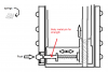
Looking at the video of the scanner again, it seems that since power needs to be transferred to the top and have it still move up and down,
a simple brass "slip rail" would do the trick nicely (no wires to get tangled and broken due to the movement) and it would give the top
a nice glide platform as well and not bind up. I know the power can also be put on the springs if using two of them but not have them
short together. You'd think wires would bunch up at the bottom when pushed in and cause it's own set of problems.
The bass rail (as I see it) looks to be too clean with sharp edges and intentional to be worn paint.
I guess if I did one like this I would use the rails for power.

Enterprise scanner.jpg

>>>>>>>>>>>>>>>>>>>>>>>>>>>>>>>>>>>>>>>>>>>>>>>>>>>>>>>>>>>>>>>>>>>>>>>>>>>>>>>>>>>>>>>>>>>>>>>
* You could also put two springs in the top part left and right of the screen and have them push down, lifting the top.
If it were done as mentioned above, this would keep the springs separated and power could then be applied to them instead
of any rails or wires.

But, if power rides with the top portion then there wouldn't be this issue of the batteries being in the bottom.

* If you can find a small EL panel (about the size of the screen) you may be able to put the power inverter in the head of the scanner
and feed the EL backlght from there.

* If anyone used the Stapleton's lighting design, maybe you could post your build here. For information sake.
I see where he used the LCD Backlight Kit-Glows Blue Turnigy 9x FlySky FS-TH9X DX6i DX7s conversion kit off eBay.
It indicates in the auction the low voltage is 8V for the panel. (SEE ADDED NOTE BELOW)

** ADDED NOTE:
I am finding out a bit more about the LCD Backlight Turnigy 9x for the RC Transmitter.
It appears that the backlight is nothing more then a bottom lit acrylic panel using an LED to light it from it's side.
The panel can be cut to size. No inverter required. The eBay auction indicates that it can run on 8v - 13v but that
is due to the fact that it was designed to be used by the power from the RC transmitter.
So, there will be a resistor in series with the LED to lower the current.
I think if this LED resistor was changed out, it could indeed light up on 2 - 3v coin cells......not sure since I don't have one here.

The video link below shows the panel being modified by the user showing that it is indeed a bottom, side lit acrylic panel.
You only need to use two wires (Plus and Minus) to power the light. There is a resistor @470ohm located in the plug itself.

https://www.youtube.com/watch?v=MWqAB5rVq8E


I am sure there are many ways to make this happen and this is just a few suggestions and really is based on how you
are able to do it.
smile.png


Just my interpretations.

.

Enterprise scanner.jpg
 
Last edited by a moderator:
It's great to see Enterprise era props getting some attention, it's a very under appreciated series.

Agreed! Enterprise is my second favorite series and was cut off too soon IMHO. I have a couple ENT props on my to-do list and hope to post them here one day.
 
Wow, thanks everyone!

@ Propmaster2000 - here is the inside of both sides.. per the photo I have 13mm of space left. This is because I redesigned the top cap piece and due to the curve lost 1mm of space ... this is corrected in the newer version so I've shorted the inner body piece (screen part) by 1mm to correct for this. So the space will be 14mm.

The ENT scanner does have a brass or gold strip on the sides. This detail is not on every prop though. It would be a great way to for a contact though, something to consider. I'm still trying to figure out how the pop up works with the top button as seen in the show ... I don't see the tabs that are used for those pop-up magnifying glasses... any ideas on that?

I'll have to check out the link...

ENTSCNR14.jpg
 
Very small update. So I've done some tinkering to the outer details and the wall thickness.

I decreased the wall thickness by 0.5mm of the outer casing and printed only the top half. So the inner top part now slides like butter. So that was nice. Now off to the pop-up mechanism and lighting design parts.

Here is a screen capture of the my sketchup file.

So I'll be making tabs (2 on each side) on the main outer casing that will do two things. I'll be able to screw the top and bottom outer casing together. The tabs will then pressure fit in the outer grips. this will give more space internally and allow for me to hold the pieces together and hide the screws. I just need to find a place that sells screws with the corresponding female receiver. Any suggestions? Eyeglass stores? Hobby shop? Online I can only find screws with bolts...

ENTSCNRSU36.png
 
Hey,
About a week ago I posted some information I came across about Stapleton using a backlight he got off eBay.
LCD Backlight Kit-Glows Blue Turnigy 9x FlySky FS-TH9X DX6i DX7s conversion kit.
I thought it was a nice way to back light transparent graphics. My research found that it was thin, LED as the light source,
low voltage and fairly bright. The light glows across it's surface very evenly. The one I have uses 2 white LEDs.
There is a 470ohm resistor in series with the LEDs on a type of connector. This light is used to back light LCD screens
in a hand-held RC remote control. It is very nice and should work well for most projects.
Below is a video showing this light as it comes.

As I mention several times, in the video "It's really nice".


https://youtu.be/5N9fqk8Yxi4
 
Last edited by a moderator:
Hey,
About a week ago I posted some information I came across about Stapleton using a backlight he got off eBay.
LCD Backlight Kit-Glows Blue Turnigy 9x FlySky FS-TH9X DX6i DX7s conversion kit.

Thanks for putting this video together. That is perfect. And it's pretty cheep.

I'm hoping to go the craft store this weekend to get an "inanimate plastic rod," springs, and little metal rods. Work on the pop up feature.
 
Thanks for putting this video together. That is perfect. And it's pretty cheep.

I'm hoping to go the craft store this weekend to get an "inanimate plastic rod," springs, and little metal rods. Work on the pop up feature.

No problem Kal Argos.
This back light would be perfect for this prop. Small, thin, bright, low voltage and not too expensive.

Have you made any progress on the spring ''pop up'' feature?
Maybe you could just go crazy and make it motorized with a miniature gear motor and lever system (not servo - may be too slow for this application).
That way it can go up and down automatically!
 
No problem Kal Argos.
This back light would be perfect for this prop. Small, thin, bright, low voltage and not too expensive.

Have you made any progress on the spring ''pop up'' feature?

That's a big negatory! Unfortunately I didn't get a chance to get the supplies. I'll try to draw out what I plan to do tho so if any one has a suggestions or improvements they post them.

Fully motorized pop-up... hmmm.. maybe but I still want to see about adding an animated LCD screen in as a future update.
 
Hey Kal Argos

There are many off the shelf, small screen players that have been used by others and seem to do the trick.
The Micro/Mini USB they use to program makes them easy to set up and reprogram in the future.
Many times a HERO prop is required to do many things, but there isn't enough room inside to "do it all".
So the propmakers make several duplicates to do a specific HERO STYLE function and when they are filmed,
they show the one that has that ability making it seem that one prop "does it all".

Having a pop up feature and an animated working screen would be the "cat's meow" and "bees-knees".
(geeze! who is this guy?)

Can't wait to see your progress :)
I know how "real" life sometimes gets in the way of the creative flow, so post when you can an thanks for the updates.


propmaster2000
.
 
Can't wait to see your progress :)
I know how "real" life sometimes gets in the way of the creative flow, so post when you can an thanks for the updates.


propmaster2000
.

Thanks propmaster2000 for all the suggestions and feedback...

Yeah, real life is hard to ignore... that and kids... so like I said realistically for Halloween its likely going to be a sticker screen..

But after that the skies the limit. The lcd animated screen is the ultimate "have it all" prop... but I have no programming experience so that is in the future for sure.

So I am still printing prototypes for fits, though I'm on to tiny detail like the "button" and "slider" or that's what I call them. Pictures below. Note the slider has a "tab" and there is a slot for the tab to fit in. The idea is a friction fit that allows for a sliding action. In one show, Lt. Reed seems to use that button like a slider.... so its an action feature. Note the screen is a hole... so I can put a light up screen or lcd screen in there. :eek:)


ENTScanr14.png

ENTScanr13.png

Lastly is my best approximation of Stapleton's ENT scanner pop-up action. It was pretty well done, so why re-invent the wheel. The sketch is extremely crude... the new PAINT program stinks... also drawing not to scale...

pop up sketch.png

And before I forget again... I did ask Stapleton where he got his little screws and threaded insert... here is the address for that...

https://m.mscdirect.com/mobileweb/p...rm=0-80+brass+insert&hasRestrictedParts=false

Next is the assembly bits to hold the screw/thread inserts, these will be hidden it the grips. The tabs for the screw/threads will fit in the under side of the grip and be a friction fit to hold the grips on.
 

Attachments

  • pop up sketch.png
    pop up sketch.png
    14.7 KB · Views: 58
Last edited:

Your message may be considered spam for the following reasons:

If you wish to reply despite these issues, check the box below before replying.
Be aware that malicious compliance may result in more severe penalties.
Back
Top