Y Wing based on the Dave G open source project

If someone can give me some measurement from an original Y-wing, I'd be pleased to modify the file as soon as I'm back Home by the end of the month.
I did this one by eye between all the photos I have of the Red Jammer and the one from Mr Ladd.

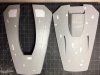
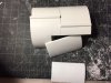
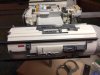
Just an FYI, if you used Stephan's files for the fins they are too long. The whole assembly only goes in so far before it rests on the cores. I needed to make new shorter ones so the nozzles didn't stick too far out of the back.

View attachment 680751View attachment 680755
 
If someone can give me some measurement from an original Y-wing, I'd be pleased to modify the file as soon as I'm back Home by the end of the month.
I did this one by eye between all the photos I have of the Red Jammer and the one from Mr Ladd.
The only measurements I can give is the distance the nozzles are supposed to stick out of the back. This is based off the old fashion way of enlarging the engine can to the correct diameter (which we know) in photoshop and using that measurement. If the measurement I came up with of 3/8 of an inch is correct that means the fins need to be 2 3/16 inches long in order for the assembly to rest on Dave's acrylic core and have the nozzle stick out the back the correct distance. If this makes any sense LOL. I think having the size of the actual studio model engine nozzle assemblies would be nice, but for the purposes of the Green Leader project and using the engine cores we have is probably the better call in this case because we don't want the nozzles to stick out too far or not enough. Just my opinion.

Something to take into consideration also is if the acrylic cores and the 3D printed ones that some used are the same size.

kg_anh_gold5-003.jpg~original.jpg
 
I just posted a STEP 3d model file of the entire Starboard Nacelle that can be used as reference for determining the length and shape of the nozzle fins... or at least my photo interpretation of them. Like Kokkari I based my dimensions on reverse engineering from photos. I used the Alan Ladd model as my primary photo reference. my dimensions are close to Kokkari's, certainly within the "margin of error". Keep in mind that there were variations between each model, including the trim length of the Saturn shell castings.

The file is in the Engine Nacelle folder in the Repository.

https://drive.google.com/drive/folders/0BwDa06cjX-frMmhuRDYzWENoVDg

Engine%20Nozzle_zpsn5wmll4k.jpg
 
A question for those who have cut the T for their build: How long did you make the pieces?

I'm leaning towards 13 1/2 inches.
 
Here are some screen shots of how I intended the Tee struts and shroud to interface. I designed a flat 1/4" pad where the strut seats to give a little extra glueing surface. This will require notching the end of the strut back about 1/8" and cutting a curved notch into which the piston parts will seat. I too plan to cut the Tees to 13 1/2" long.

Tee%20Strut%20Shroud%201_zpsatmyo2ci.jpg


Tee%20Strut%20Shroud%202_zpsrcj3swne.jpg


Tee%20Strut%20End_zpsqbuuuugu.jpg
 
Has anyone figured out what kit the struts come from?

I'm not 100% certain, but confident that the Tamiya 1/35 Hanomag Sd.Kfz 251/1 (Kit #35020) is a fine kit to use for struts that will fit, parts B16-B18, modified to create the T-bars at both ends. Looks like you'll need at least two kits to make enough for one Y-Wing, but for my money DaveG's Shapeways versions are spot on, and super crisp in their detail. DaveG's struts obviously fit DaveG's rear ventral shrouds like a glove, but the lengths and widths of the Tamiya Hanomag are also right in that exact ballpark, with wiggle room of what looks like 1mm or less on any dimension. I'm working on my hand-made set this weekend because, you know, it builds character, and will take/post some comparison shots when finished.
 
Chipping away on Thanksgiving night here. The bottom aerodynamic pod isn't attached yet and is a little out of position in the pic.

I used the Ladd Y and Julien's new version for reference. His pics really helped out since he's got the underside layed out. He did mention that he has pyro pics, so I'm assuming the underside relates to that. Otherwise, there's only one shot of the underside in 3/4 view of the Ladd Y, and it's pretty fuzzy.

Next comes some engine/tee rod work.
 

Attachments

  • IMG_2408.JPG
    IMG_2408.JPG
    308.6 KB · Views: 322
Some more progress.

In order to make the covers that go outside of the nacelles, which must cover the mounting points there, I used the same parts of the saturn v. In order to not have to buy another kit, I cemented the ends of the cut offs together very carefully to not have much of a seam between parts. I then cut out the parts and beveled the edges as needed. The parts in the pic are just a little too long. I ended up having to remove about 3mm more.

Next up: start to cement tees in place and cover the nacelles with my roboterkampf approved rising detail assemblies.
 

Attachments

  • IMG_2409.JPG
    IMG_2409.JPG
    837.5 KB · Views: 310
That's so funny Scott I did the exact same thing! It's like looking at an exact clone of what I did. I originally thought that the saturn shell wouldn't look thick enough, but after creating the beveled edge it looked right.
 
Some more progress.

In order to make the covers that go outside of the nacelles, which must cover the mounting points there, I used the same parts of the saturn v. In order to not have to buy another kit, I cemented the ends of the cut offs together very carefully to not have much of a seam between parts. I then cut out the parts and beveled the edges as needed. The parts in the pic are just a little too long. I ended up having to remove about 3mm more.

Next up: start to cement tees in place and cover the nacelles with my roboterkampf approved rising detail assemblies.

Scott,

Can you give us the measurements of your nacelle covers? I was guessing on mine, eyeballing it from reference pics, and would love to know what you came in at.
 
The cans are done. I ended up using parts from 18 of the resin engine assemblies. The last 6 or so because I needed all the blocky protrusions that surround the rear of the engines.

I used mostly the left, right and underside views of the Ladd Y to place everything. There are still a few mystery pieces used that I can't ID.

I was lucky to get the yamato rising cast parts in a trade for some H&R brick sheet. I could only ID two places, on one engine, where the brick sheet was used on the Ladd Y.

Next up is the wing work I think. I don't want to put the end pieces on the tees until later so I don't knock them around while working on the rest.

I'm hoping to have Dave's new neck to work with soon too.
 

Attachments

  • IMG_2414.JPG
    IMG_2414.JPG
    503.5 KB · Views: 364
  • IMG_2415.JPG
    IMG_2415.JPG
    484.4 KB · Views: 389
The cans are done. I ended up using parts from 18 of the resin engine assemblies. The last 6 or so because I needed all the blocky protrusions that surround the rear of the engines.
.
A question about the triangular shapes at the end of the engines , does anyone know what these are off , i was confused by a shot of the rear of the starboard engines and the triangular pieces look part of the Saturn engines , I thought I had the wrong kit, but I now realise this engine was a casting , not the original styrene kit .
IMG_4777.JPG
 
I've always assumed they were scratch built from a bit of styrene and added to the engine patterns before casting. I've modeled them up and was going to 3D print at Shapeways in Extreme Detail Plastic them so they would all be identical. I'll post the files if anyone else wants to do the same.
 
This thread is more than 6 years old.

Your message may be considered spam for the following reasons:

  1. This thread hasn't been active in some time. A new post in this thread might not contribute constructively to this discussion after so long.
If you wish to reply despite these issues, check the box below before replying.
Be aware that malicious compliance may result in more severe penalties.
Back
Top