1/10 scale Apollo 13 Lunar Module and Command and Service Module

Aries1b

New Member
Inspired by the amazing Lunar Module Eagle build by Crackerjazz here on RPF, I decided to design and construct a 1/10 scale Apollo 13 CSM/LEM stack together with a display stand. The end goal is that the model with be on display and used as a lecture prop in a series of space lectures in the UK, the first of which will take place at the end of Oct 2015. You may have noticed that the deadline has already passed. I actually started this project 6 months ago and it has been pretty intense at times, especially as the deadline loomed ever nearer. As such, I have not had time to start a thread until now.

So, this is a retrospective thread and will catch up with the present time quite quickly. The model is presently at a stage one of completion, meaning it looks finished but lacks fine detail and work will continue to add details in the coming months.

My thanks to Crackerjazz for sharing links, info and tips at the start of my build some 6 months ago. I don't know if I'll ever be able to replicate the incredible detail in his model but I may get there one day.

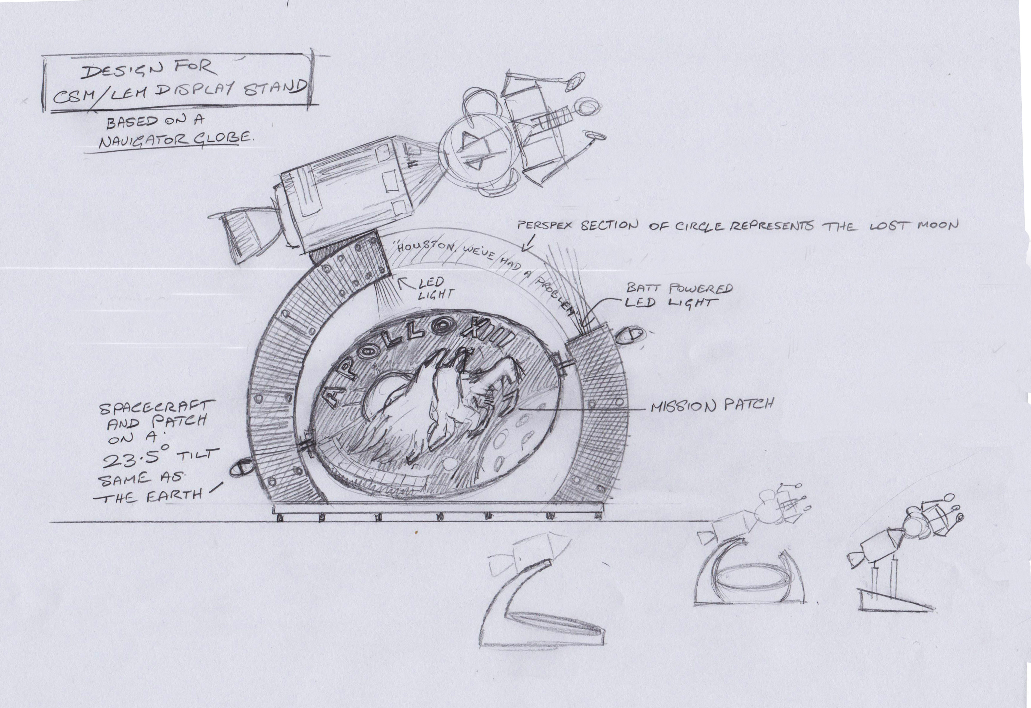
Here's a rough sketch of my design on the back of an envelope

attachment.php
 

Attachments

  • drawing_edited-1.jpg
    drawing_edited-1.jpg
    1.5 MB · Views: 2,622
Last edited:
Here's the MDF stand under construction


attachment.php
attachment.php
attachment.php
 

Attachments

  • apollo stand 007.JPG
    apollo stand 007.JPG
    4.7 MB · Views: 1,398
  • apollo stand 013.JPG
    apollo stand 013.JPG
    4.7 MB · Views: 1,321
  • apollo stand 017.JPG
    apollo stand 017.JPG
    5.3 MB · Views: 1,320
Last edited:
The stand is constructed using 150mm bolts then painted with a grey primer/undercoat. The mission patch has been printed on to a 1000mm wide Alupanel disc.

The service module substructure consists of a disc of MDF at each end of a simple timber framework which was then covered with a sheet of flexible MDF.

Within the framework is a cross-brace for strength.

A steel support bar is fitted into sockets in the service module framework and runs from the rear of the service module, through both ships to the lunar module descent stage engine well.

The access hole seen in this picture is for locating the rear socket when installing the tube and for locking it into position with a screwdriver.
attachment.php
 

Attachments

  • Apollo 13 model 047.JPG
    Apollo 13 model 047.JPG
    4 MB · Views: 1,313
Last edited:
all the best designs are :thumbsup
very impressive gimbal , is the patch a mission coin that will spin, or just pinned at an angle ?
Looking forward to seeing it

The patch does pivot but is intended for a static display. It was easier to make it pivot than to fix it and make it look like it pivots. thanks for your comment :)
 
Last edited:
Aries1b, I bow to thee :) You are light years ahead in skill and nothing seems impossible for you. I'll be glued to this thread to watch your progress. If not for the distance I'd probably wear out your doormat.
 
Thank you Crackerjazz, but this thread wouldn't be here if not for yours :)

Making the Command and Service Module engine.

I considered several methods for making this large engine bell including making the correct shape by using clay on a potters wheel before making a plaster mould then casting it in GRP. However, the quickest and cleanest method seemed to be the one I eventually decided on (pictured below}. I enlarged a side view picture of the Apollo 15 CSM engine bell and made a profile card from that. The next step was to cut out a series of MDF circles and fix together with screws into a rough engine shape slightly larger than the finished engine would need to be.

This stack of circles was then attached to a lathe. Using woodworking tools, I carefully honed it down to the correct shape, checking the curve of the engine with the profile card.
While still on the lathe, sandpaper was used to achieve a smooth finish.

At this point I wasn't sure what to do with it but at least I had the correct engine bell shape!
attachment.php
attachment.php
attachment.php
attachment.php
 

Attachments

  • csm engine 009.JPG
    csm engine 009.JPG
    2.8 MB · Views: 1,136
  • csm engine 005.JPG
    csm engine 005.JPG
    2.7 MB · Views: 1,174
  • csm engine 001.JPG
    csm engine 001.JPG
    2.4 MB · Views: 1,175
  • csm engine 014.JPG
    csm engine 014.JPG
    2.6 MB · Views: 1,146
The 1/10 scale CSM engine bell with a 1/72 scale Dragon CSM for comparison.
attachment.php
 

Attachments

  • csm engine 026.JPG
    csm engine 026.JPG
    4.8 MB · Views: 1,136
Vac-forming slightly less than one half of the CSM engine bell using 2mm styrene sheet. I would need three vac-formed pieces to make an engine.

I cut an engine shaped hole in the peg board that formed the top of the vac-forming box and sunk the engine into it leaving just less than half showing. This meant the MDF engine former would remain intact as it would be needed later as a solid core, around which I would cut, trim and glue the three moulded engine sections together. When set and the joints sanded smooth, the lightweight styrene engine simply lifts off the former.
attachment.php

attachment.php
 

Attachments

  • csm engine 027.JPG
    csm engine 027.JPG
    4.8 MB · Views: 132
  • csm 025.JPG
    csm 025.JPG
    4.1 MB · Views: 1,114
  • csm 034.JPG
    csm 034.JPG
    4.2 MB · Views: 1,094
Last edited:
That is very very impressive. I'm looking forward to seeing the progress. Some phenomenal skills there, and such clean clean work.
 
Is it not possible to vacform over the thruster buck with it stranding to eliminate joins

I did consider doing that but as this was my first ever go at vac-forming I thought it better to play safe. I envisaged creasing and folds in places had I attempted it. I may try what you suggest if I need to repeat the exercise though.
 
3d printed thruster bells designed by Crackerjazz (Check out his incredible Lunar Module build here on RPF) and acquired via Shapeways. Here being fitted to the CSM thruster housings.
attachment.php
 

Attachments

  • thrusters 007.JPG
    thrusters 007.JPG
    4.6 MB · Views: 1,006
Last edited:
Command module framework being fine tuned on the lathe.

attachment.php
 

Attachments

  • command module 031.JPG
    command module 031.JPG
    2.2 MB · Views: 805
Last edited:
This thread is more than 5 years old.

Your message may be considered spam for the following reasons:

  1. This thread hasn't been active in some time. A new post in this thread might not contribute constructively to this discussion after so long.
If you wish to reply despite these issues, check the box below before replying.
Be aware that malicious compliance may result in more severe penalties.
Back
Top