You are using an out of date browser. It may not display this or other websites correctly.
You should upgrade or use an alternative browser.
You should upgrade or use an alternative browser.
AceSG, Three years with no particular timeline to finish. I will be releasing the design to the whole project once complete. I have already released the "unfinished" CAD files, see earlier in the thread, or the first post. Even with the full set of CAD files, this is a very complex project. It will never be a "3D Print this at home!" style project. The final build will involve commercial 3D Printing, laser-cutting, casting, thermal bending, electronics, and software.
Last edited by a moderator:
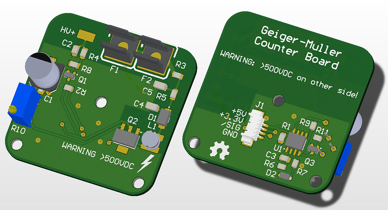
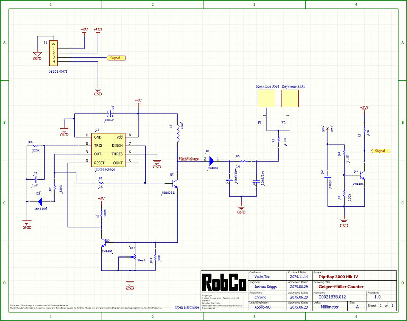
The Geiger–Müller tube radiation detector board design is complete. Again this is based on the PiGi design.
I replaced the four pin inductor with two pin inductor, so no high voltage will be accessible after the board is installed.
The Geiger tube will sit in the two fuse clips at the top, with a short wire connecting the end of the tube to the HV+ pad.
You are an absolute machine, sir. I sit in awe of your engineering skill.
undeadmith
Active Member
this is amazing, i am in awe!
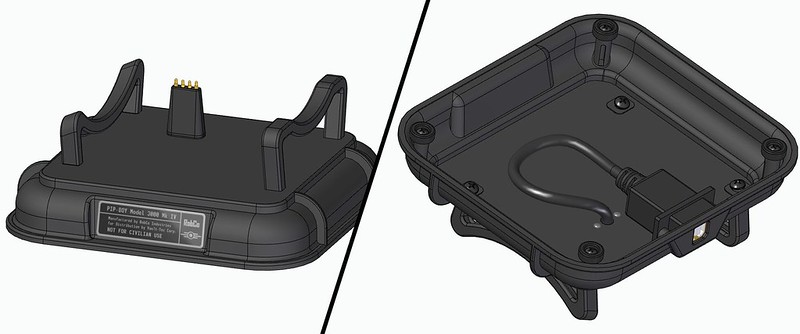
One feature I have wanted from the start of the project, is a way to keep the Pip-Boy powered even when it is docked. So I re-designed the dock so that it has four spring-loaded Pogo-pins. These will allow the Pip-Boy to dock and both charge and connect via USB.
Even when docked, new connector will be barely visible, as it is hidden behind the latch.
----------------------------
However, unlike the official bluetooth edition, I am not willing to add a ugly protrusion the outside of the Pip-Boy.
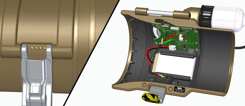
The external connection on the Pip-Boy is done using four small gold pads. They also very well hidden inside the space where the latch connects. These are wired to the same USB connection as the retractable cable.
I'm fine either charging mine through the USB cable on the probe or with an induction charger.
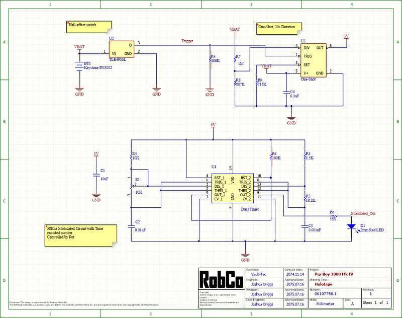
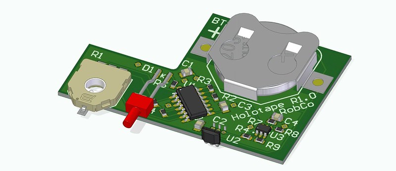
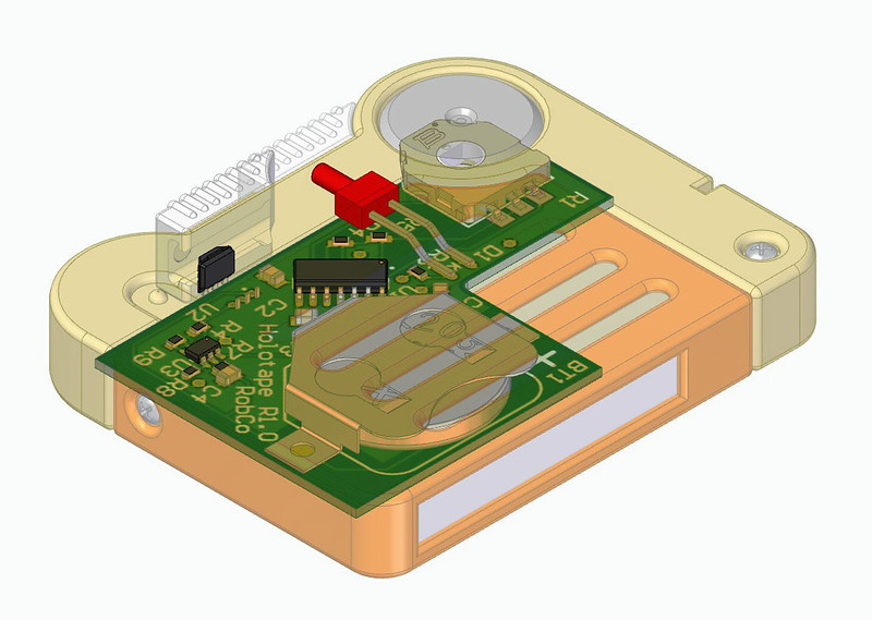
Today was more electronics. The Holotape circuit board. This is one of the last peripheral boards I need to do before starting on the motherboard.
I am sticking with the optical data transmission on the Holotape. Afterall, it is just cool that it uses actual optical data transmission.
Here is how it works for those who haven't read the earlier parts of the thread:
1) When you open the Holotape dust cover, a small magnet is moved in place over the Hall Effect Sensor.
2) The Hall Effect sensor triggers the one-shot circuit, which in turn powers up the Dual Timer Circuit for a period of 30 seconds.
3) The first portion of the timer circuit generates a 38KHz carrier signal, the same type used for Infrared TV remote controls.
4) The second portion of the timer circuit generates a variable pulse width signal. Controlled by the potentiometer.
5) The modulated timing signal is then transmitted out via the red LED.
6) After 30 seconds the Holotape is automatically powered down by the one-shot circuit to save battery life.
7) It can be re-triggered by closing/opening the dust cover.
On the Pip-Boy:
1) When inserted into the Pip-Boy a small detector switch will detect that a Holotape is present.
2) A second magnet inside will actually trigger the circuit upon insertion, just in case you forgot to open the dust cover. (The translucent cover won't stop the IR signal)
3) A 38KHz IR Demodulator chip on the Pip-Boy will decode the signal, and pass the pulse-width signal to the microcontroller.
4) The microcontroller converts the pulse width signal into a number, and this is compared to a set of ranges.
All of this means the Pip-Boy can have up to 12 different ID codes variably controlled. So you can remove the Holotape, and turn the knob on it to set it to some other tape configuration. (Game, Log, Audio, etc...)
Basically the Holotape becomes a very complicated remote control. It tells the Pip-Boy software what preprogrammed Holotape to load.
I did look at adding some actual two-way optical data communication using IrDa and a tiny Arduino, but the battery in this case wouldn't last very long, and the software would become much more complex.
Last edited:
drewthecostumer
Active Member
This is SUCH a project! I love it! Following with great intrigue!
*drools incoherently*
So I could leave the pot on each tape in one position to permanently make it one 9f the game tapes, or a specifically marked personal log or like that?
Short answer:
Yes, that is the idea. You can set the potentiometer to one of 12 settings, and then program what setting is what in the PIp-Boy. By making it adjustable you won't have to have 12 separate (expensive) holotapes, you can just change the setting as you want.
Overly detailed answer:
Since the pot and timing circuit are analog, technically you could have hundreds of possible timing outputs. But in reality the position of the pot won't be that stable. So the idea is to mechanically put in 12 detents into the knob. (12 happened to work out to a nice even pattern around the small knob)
The detents help the pot settle on a number by mechanically holding it in position. Even then there will be some drift.
So if we are using 8-bit range of numbers that is a 0-255. Lets say the pot is set to half-way around. The output is ~128. The microcontroller might end up reading 128 exactly, but the number could drift on either side of 128. So we use every electrical engineers favorite word: Hysteresis. You compare the raw number you have to a range of numbers. If we device the 0-255 in 12, then the range is approximately +/- 10 on each side of the target number. Anything in that range is considered a valid input. Software compares the number to a set table, and calls up the correct command.
In the end the holotapes are going to just be another gee-wiz feature. I imagine having around three tapes that you can swap out and show off different programs.
Well today marks an occasion: I have officially run out of mechanical design tasks on my list!
The only feature I think I haven't been able to really get in was a stronger wrist attachment. But that can be added later without changing the rest of the design, as I have both screw and magnet attachment points. Everything else is now as good as I can design in CAD. I am sure prototypes will reveal lots of tweaks to make.
I won't be rushing to make SLS printed prototypes at this time. The electrical design tasks may push some mechanical changes. Also, all the 3D printed parts alone will cost $500 to produce on Shapeways. And I have quoted the most expensive parts through multiple online suppliers, Shapeways always seems to win out. Although I will keep looking for the best 3D printing shop for this. If I take long enough the Fuse 1 may arrive before I am done.
I will be making lots of FDM printed prototypes. I will build prototypes in small sections like I did earlier. There are also lots of non-3D printed parts to prototype also.
------------------
There is still a ton of electrical design work to do. But since I am now using the extremely popular Raspberry Pi, I should be able to order pre-made prototype boards and test most things. Even then, it will take a lot of time to research all the best options, test and integrate them.
For example here is the list of items I need to design:
-Motherboard with lots of connectors
-Lots of various power regulators, and power control circuits.
-Air Core Motor Controller.
-Audio output, mic input.
-OLED Power circuit.
-OLED Control. (DSI with HDMI as a backup.)
-USB, both from comms cable, and an internal debug.
-GPS module.
-Compass modules.
-WIFI and Bluetooth modules.
-Real Time Clock.
-Holotape interface.
-Analog input interfaces.
-LED control and boost circuits.
-FM Radio circuit (Still a maybe).
------------------
Also, a new set of epic set of 3D renderings will be forthcoming.
Last edited:
Macgeoffrey
New Member
So I've been stalking this thread for a couple years now, can I just say this whole project is amazing! It blows me away how detailed this thing is. Sorry this is probably off topic, but I had a question. I'm getting into custom electronics and stuff like this too, and I'm currently designing some custom PCBs like the one's you've been posting. What service do you recommend ordering custom PCBs from? Where will the ones from this project be coming from?
What service do you recommend ordering custom PCBs from? Where will the ones from this project be coming from?
I haven't decided who I will order the boards from yet, so I can only tell you who I have bookmarked from my research:
1) macrofab.com. They are local(ish) to me in Houston. What is cool is they have a ton of pre-populated commonly used components which they will populate on their boards for cheap. But they are not the cheapest board house to start. They have a podcast I listen to every one and a while with some good tips.
2) OSHPark.com. Their boards are made in the USA, and they are still pretty cheap yet still fast, especially for 4-layer boards. However, every board comes in purple.
3) pcbs.io Cheap for small boards, all boards come in black. They have a cool board sharing feature, letting anyone order a board you made through them.
I am probably leaning towards using PCBs.io for the small boards. My main board will be at least 4 layers, so I will probably prototype that with OSHpart, and get a final board made somewhere else. (I actually want green boards just because the Pip-Boy isn't supposed to be a modern slick device)
If your following this project, you might want to check out my side project: The Vault-Tec Scientist Radiation Dosimeter. (I think most the RPF regulars already have seen it)
In either case, while working on it, I had to find a battery capable motor control chip. And whatever I use in the Dosimeter will also be used in the Pip-Boy.
I have narrowed my search down to the Texas Instruments DRV8848 Dual H-Bridge Motor Driver. This is one of the few drivers I could find that could operate at 5V, but also go up to as high as 9V if needed.
TI even sells a development board that will get me started. The board connects to their ultra cheap MSP430 microprocessor development boards. I even already had one! (Somewhere in the piles of remaining moving boxes)
-------------------
Here is the thing, the MSP430 has built-in IrDa logic. That means it can transmit and receive serial data over a optical link without any external circuitry besides the IR transceiver.
So here is the question:Should I upgrade the Holotapes have two-way optical data communication?
Even if I don't do two-way communication, the MSP430 also makes IR remote control signal transmission quite simple, and very low power. So I may end up using it just because it is actually more foolproof than the Dual 555 timer circuit I have now.
I am sure two-way data would take more energy. However I think I can fit in a rechargeable battery into a tiny holotape.
As far a storing that data, I would add a flash chip. You can get up to 1Gb (125MB) of flash in a tiny package.
It seems like this sounds really cool, but could end up taking a heck of a lot of software work for what becomes bragging rights on where the actual data is stored.
Last edited by a moderator:
The 3D printer at work has been turning out parts all week. I don't have everything done yet, but there is enough to get excited about.
The above is just a prototype. I never planned on building the final thing using FDM 3D printing. That said, holding the physical object my hands is pretty cool.
The size feels just right. It fits on my arm well, but I expect that some of the padding will end up too tight, and some too loose, so perhaps a custom mold may be in order. Since the padding will be magnetically attached, you can swap it out for a decorative game-accurate version for display.
The hinge, and closure work great. The clasp works, but needs tweaking to become perfect.
The radio knob already works perfectly despite things being held together loosely. So do the other knobs.
The USB connector retraction mechanism is very finicky, so I will have to revisit it.
I already have a huge list of small changes to make assembly and fit a bit better.
--------------------------
This is what the front half looked like at the end of a 36 hour 3D print. It was printed at 0.1mm thickness per line for maximum resolution.
The printer is a Ultimaker 2 Extended, using ultimaker brand silver PLA.
--------------------------
More than half of the plastic used was just for the support material. It took almost two hours just to remove all the supports. A printer with dissolvable support materials would help greatly here. If you didn't know the inside design, you would have a hard time figuring out what to remove and what to keep.
The supports did great in most areas, no sanding needed, just some light scraping.
--------------------------
I was impressed that nearly every internal feature turned out to workable for this prototype. There are a few clogged holes, some which are impossible to get to drill, so those parts will end up heat-set. Even with fairly weak PLA plastic, the whole piece is quite stiff. When I make it from solid nylon it will be rock solid.
There are a few dimensional inaccuracies however, each hole is a bit too small and oblong shaped. A few places where parts had to slide past each other required grinding, despite there being 0.3mm of clearance.
--------------------------
The back half was a similar story. It took 18 hours to print. Most everything except the snap-fit electrical switch came out great.
--------------------------
I have lots of hardware and electrical parts to order before I can build a full working mechanical mockup, but I figured y'all would like to see it coming into physical form.
Last edited:
Woooooooowwww, that is beautiful. The reality of this whole thing just got more... real...
orion42m, I am using SolidEdge. One of the best CAD programs on the market, but also not priced for a home user. I get to use it as its my daily software at work.
I have talked about it a few times, but I am sure it is buried deep in this thread, so here it is again. Also I don't work for them, but this will sound like a sales pitch. I haved used over a dozen different CAD programs over the years, and working in SolidEdge is just a joy.
SolidEdge is not to be confused with Solid Works. Solid Work is lower cost, more popular program, but not as capable. What makes SolidEdge so amazing is just how it handles modeling in "Synchronous mode". You see most CAD software such as the low-cost Inventor software work the same as old-school AutoCAD. Where every thing you do is based on a hard sketch, and then you build up a long history tree as you model. If you want to change the diameter of a hole you made 25 steps back, you have to go back and edit that step, then hope that when all the new steps are laid on top, that nothing breaks. This method of CAD design dates back to before the mouse was invented. And while some programs are getting options to allow later edits with more ease, they still don't work like SolidEdge does.
How SolidEdge works is that you still use a sketch to make your initial shapes, but there is no history required. Instead design becomes more like sculpting, but with the power of parametric modeling still there. I can add and remove features at will, with no regard to when that feature was made. I can alter things in the model without ever worrying about a history tree. It takes 3D CAD design and makes it just getting to a end-product. And less a exercise in fighting the CAD software.
I don't think I could have made the Pip-Boy in any other program. I could have made something that looked like a Pip-Boy, but I wouldn't have been able to make the thousands of small tweaks and changes as I worked.
------------
To answer the 2nd part of your question:
Yes, I plan on releasing the whole design when I consider it complete. That will include native SolidEdge CAD files, STEP files and STL files. The PCB designs that are mostly complete are already available on CircuitMaker. (I say mostly, as nothing is done until I have it in my hands, and have no future changes)
I also plan on making an assembly document, and making it lore friendly like I have done with the PCBs. I will probably do a CAD drawing for each component also, just like I do with my day job. Making this as real as any fully designed product.
------------
Update based on 3D printed physical model:
Actually putting together the physical model always means changes. Most things went together great, but I am striving for perfection here. Here is the raw list of changes so far:
1) Flip captive pins over and use shoulder to hold springs instead of retaining rings
2) Make hook on latch less aggressive, add more clearance at top edge.
3) Add more clearance to lower latch arm
4) Re-think pin assembly order on eject button
6) Re-do mount design for top springs
7) Chamfer brass screw holes.
8) Tighten wobble on all knobs
9) Add set screw behind selection wheel detent to allow adjusting tension
10) Figure out a better way to retain all knobs
11) Swap detent on macro knob from body to the knob itself.
12) Make selection wheel sound less resonate
13) Make catches on reel longer
14) Change on/off switch to be retained by metal pins instead of snap-fit
15) Double check long shaft diameter
16) Add spring pin or other better snap-fit to the comm cable
17) Make USB connector retraction mechanism more fool proof
18) Figure out way to make bottom latch tension adjustable
19) Rotate catch points on spool for free release at end of cable
20) Angle top right screw hole on back insdie
21) Look at adding battery removable style cloth pull tabs to padding.
22) Add stops to helix carrier
23) Add more pins to radio knob board so LEDs are parallel instead of series.
Last edited by a moderator:
Similar threads
- Replies
- 2
- Views
- 319