Randy Cooper Stardestroyer - Assembly description

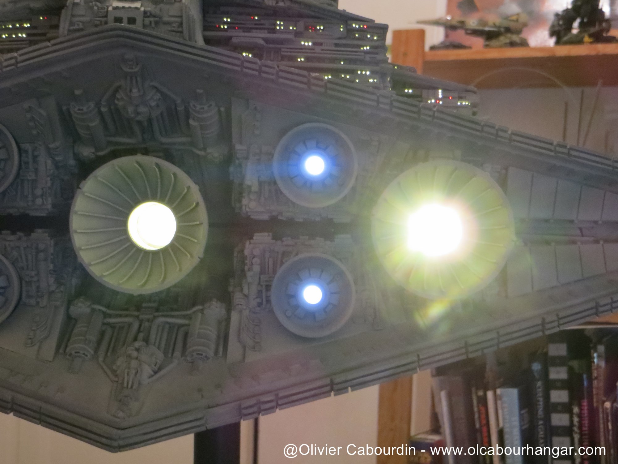
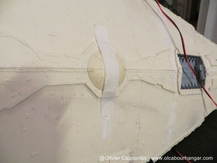
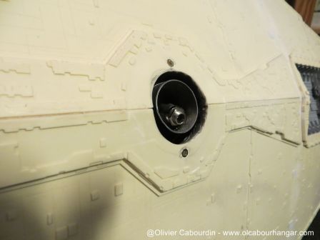
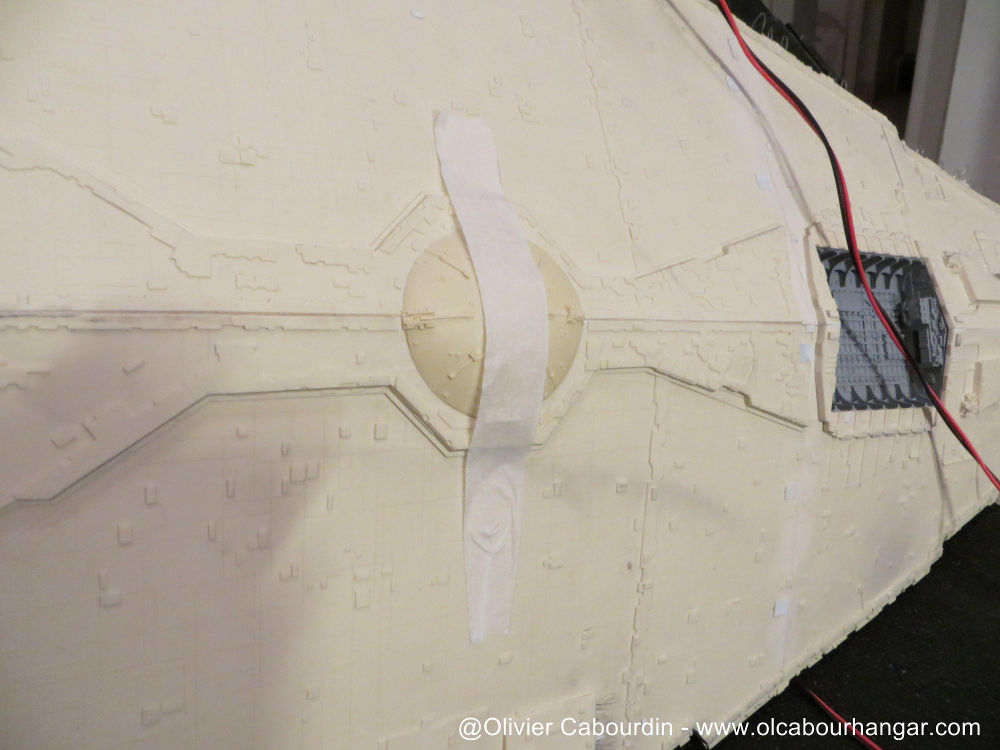
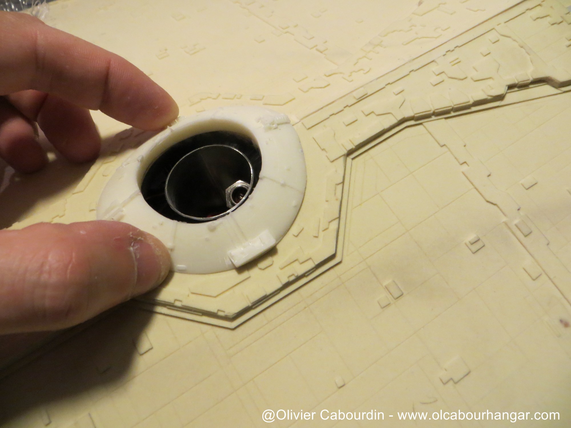
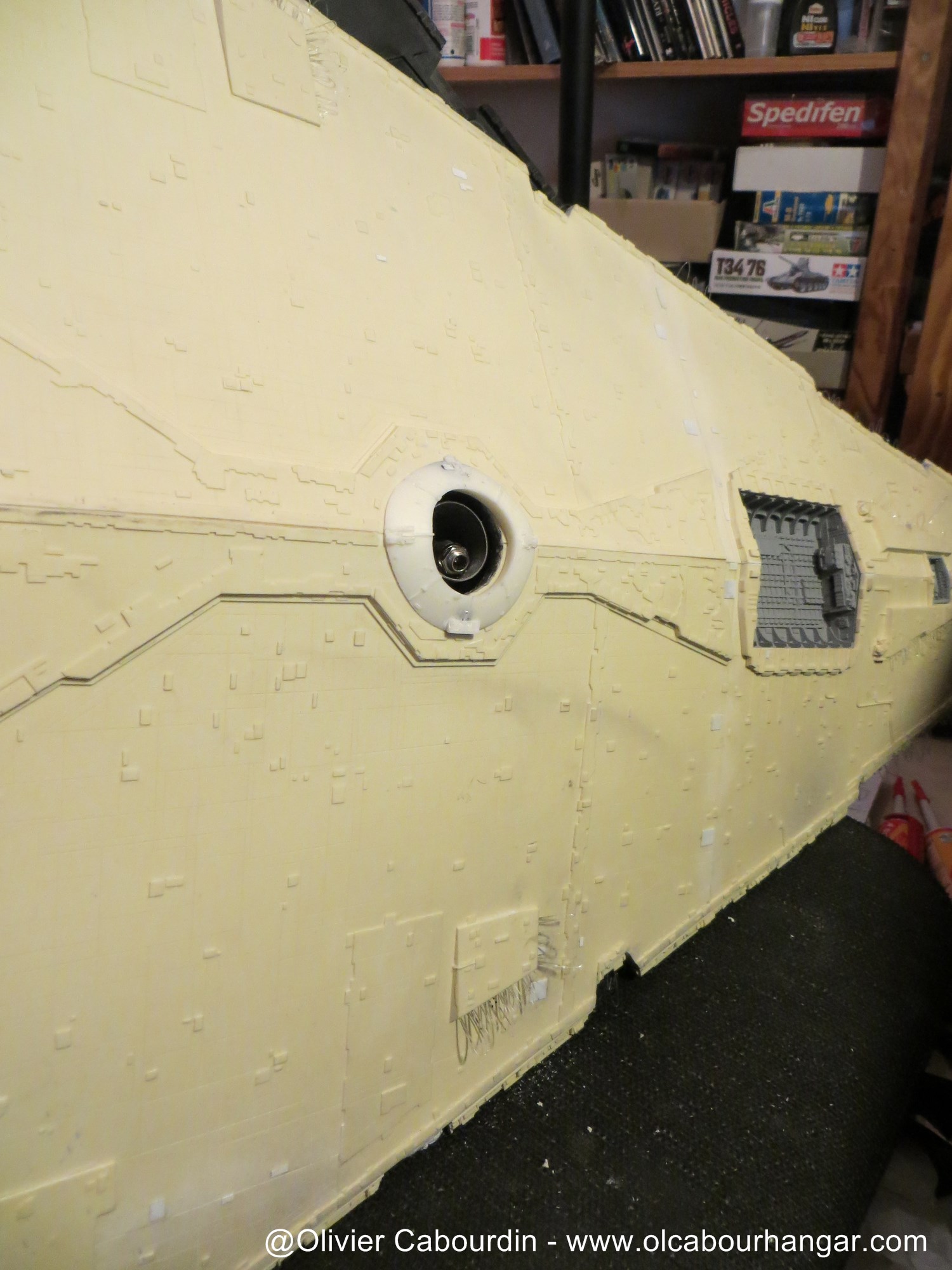
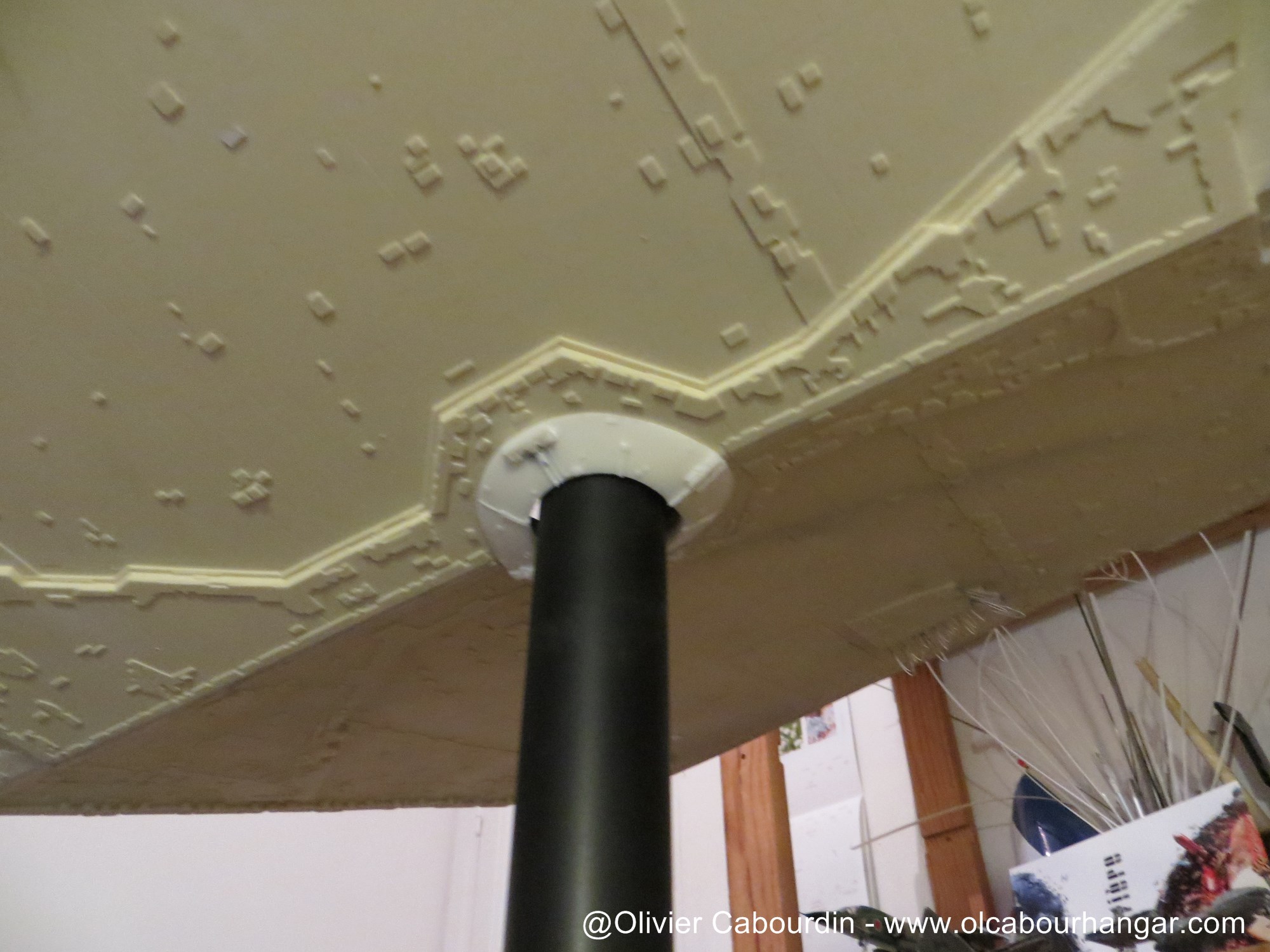
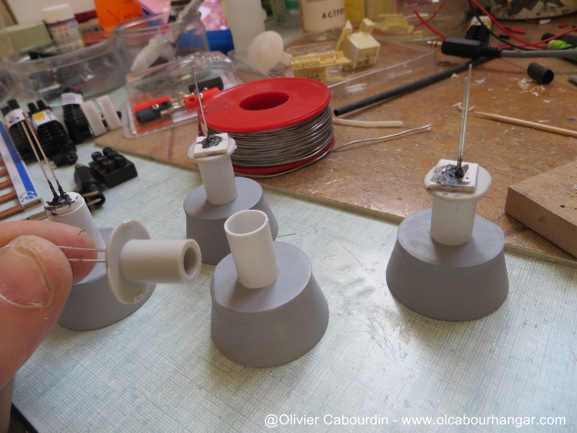
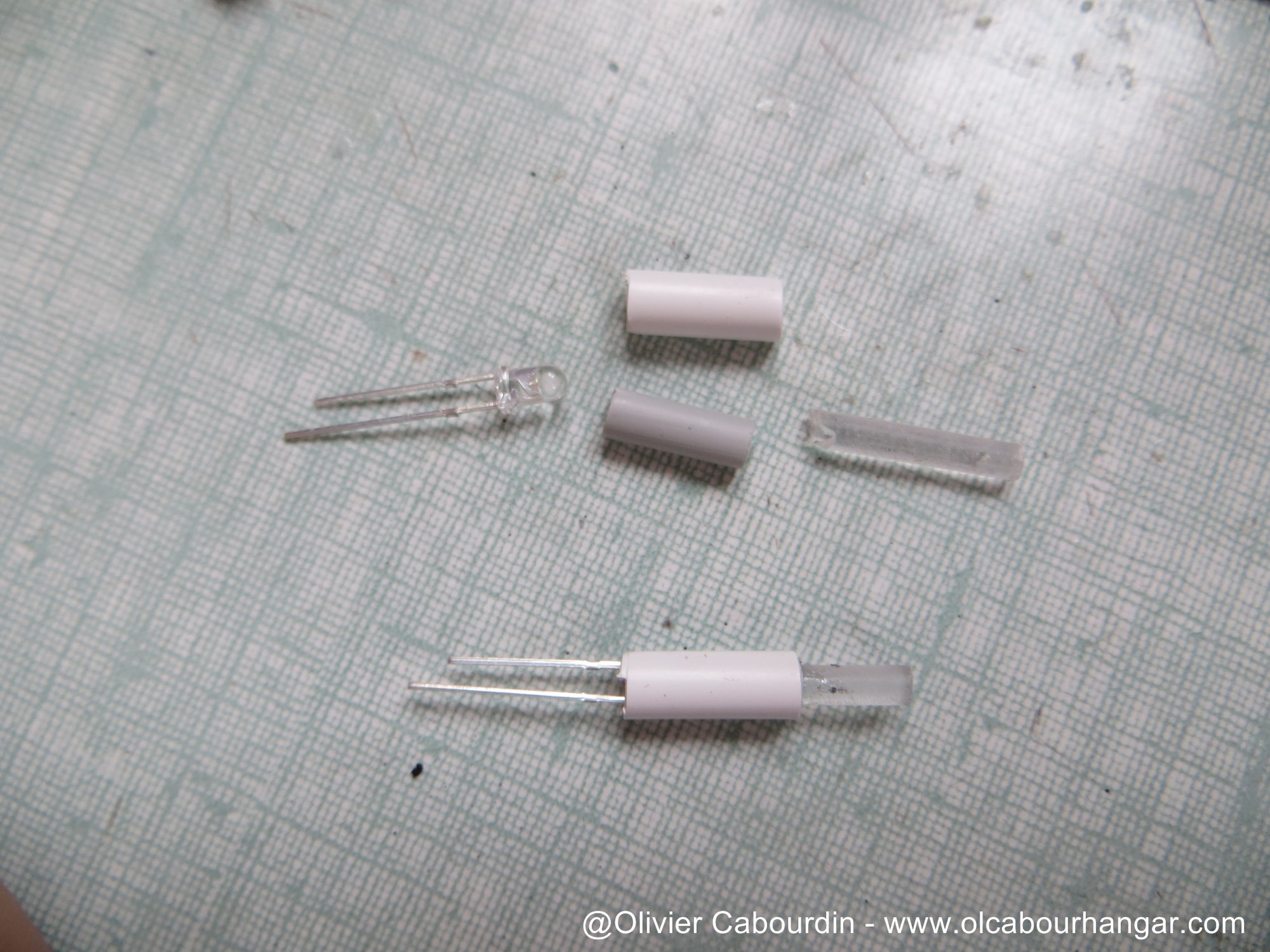
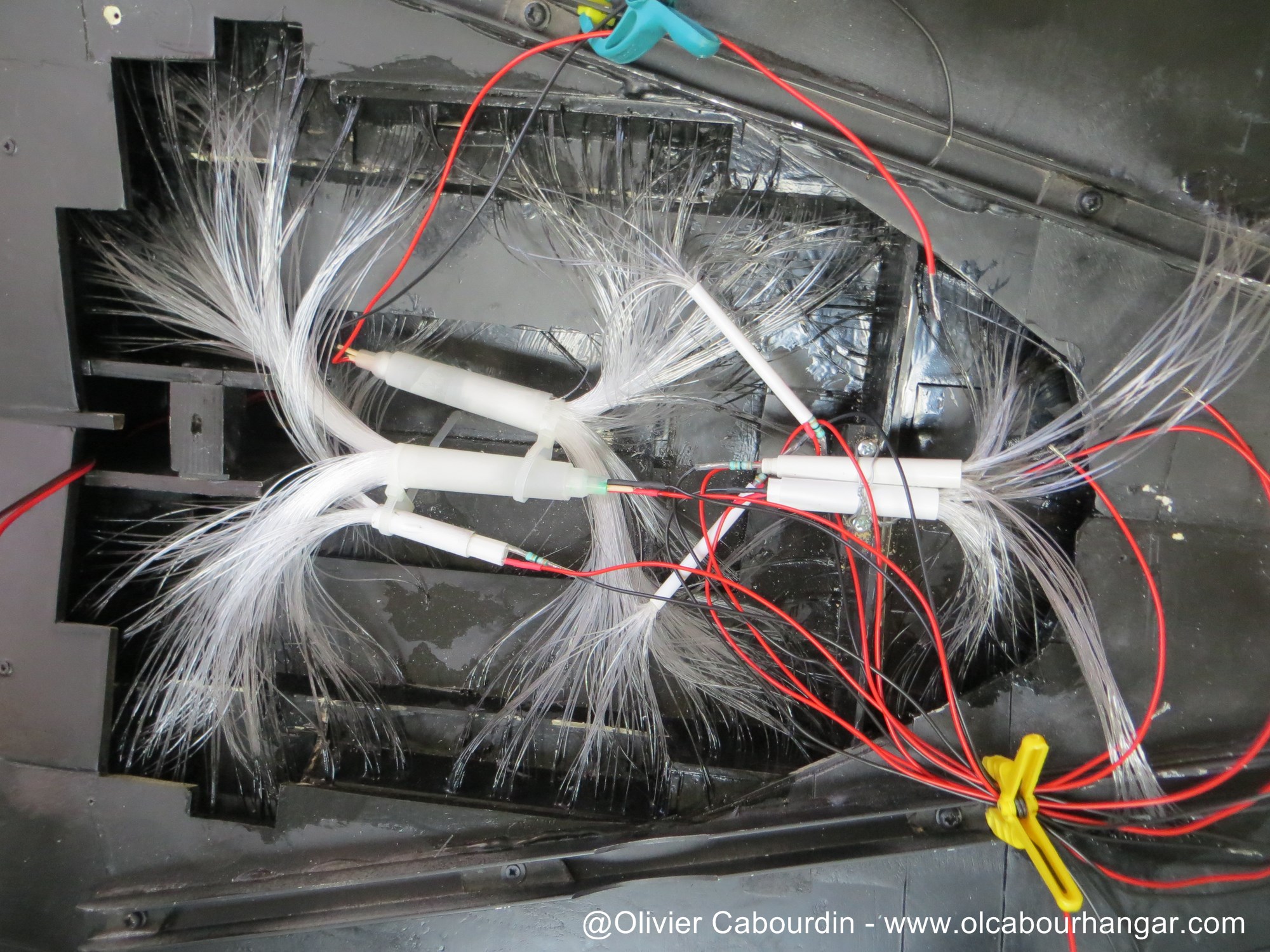
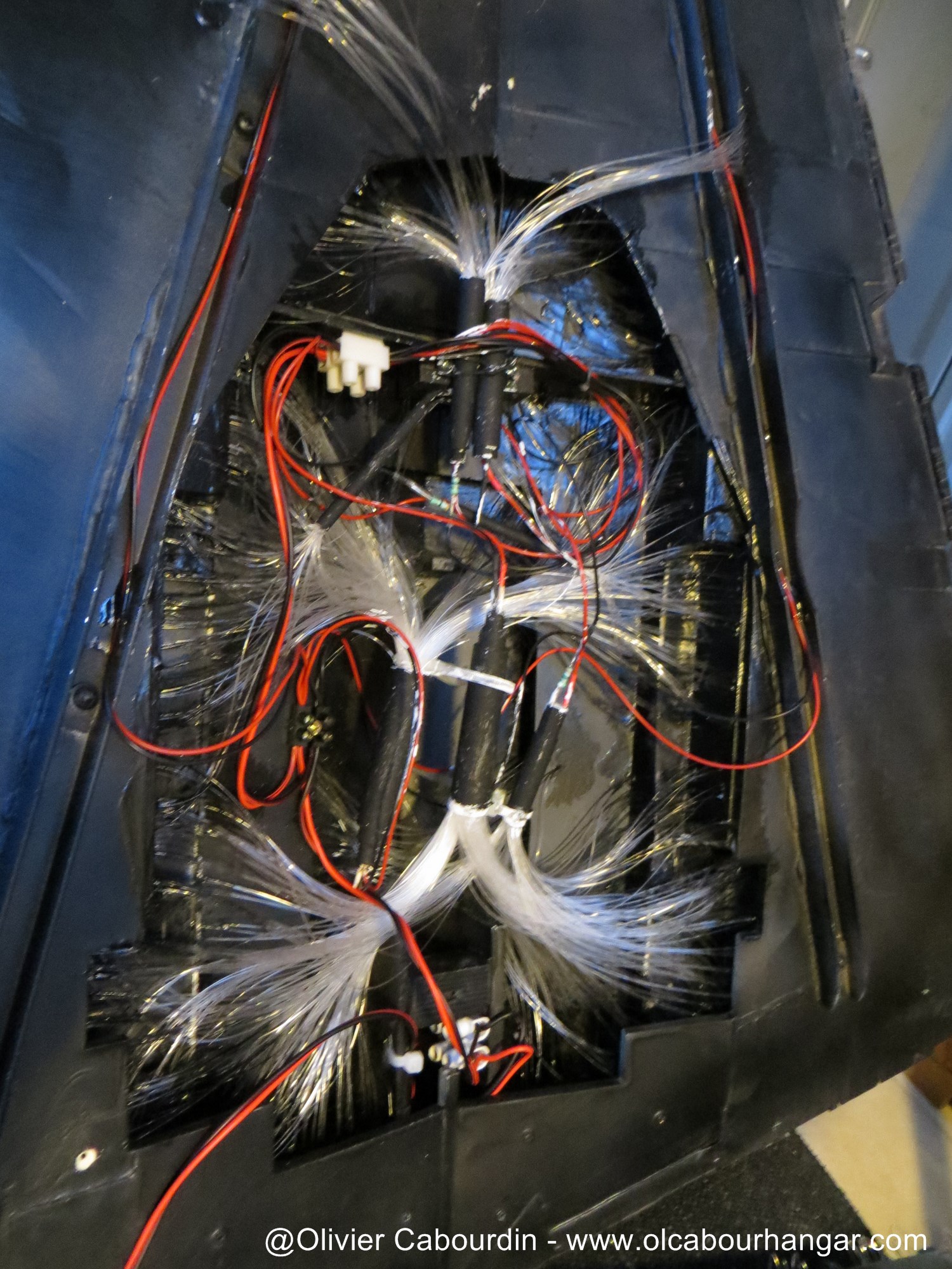
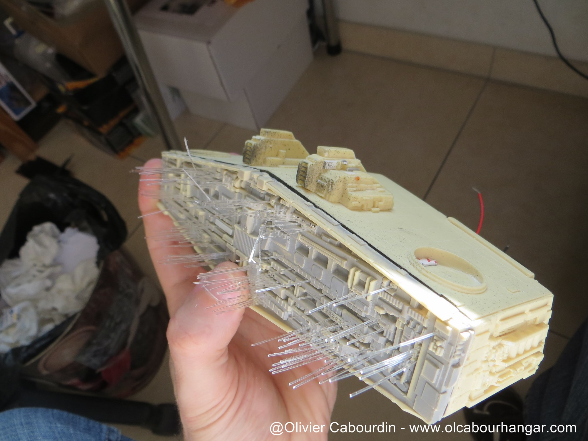
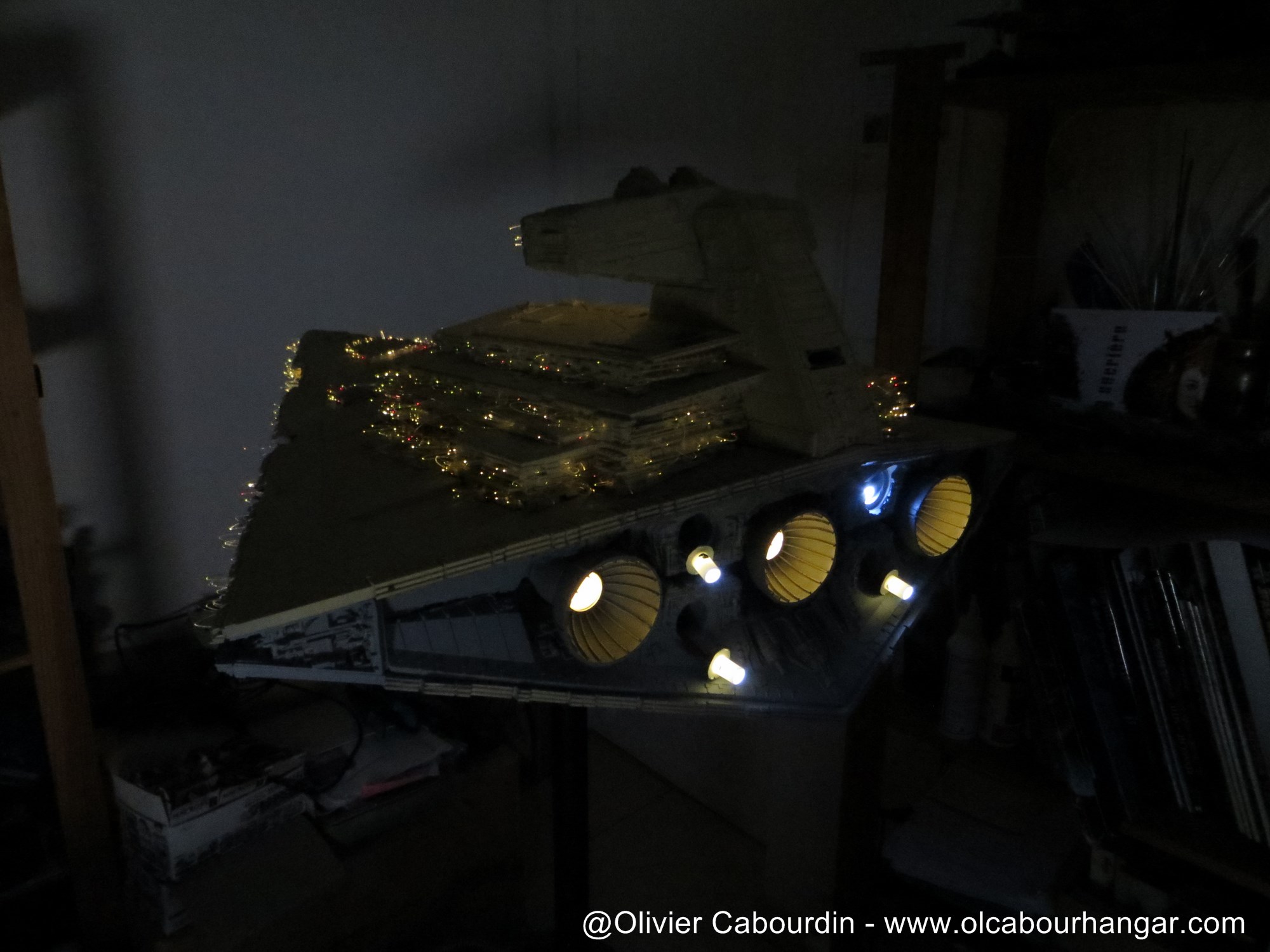
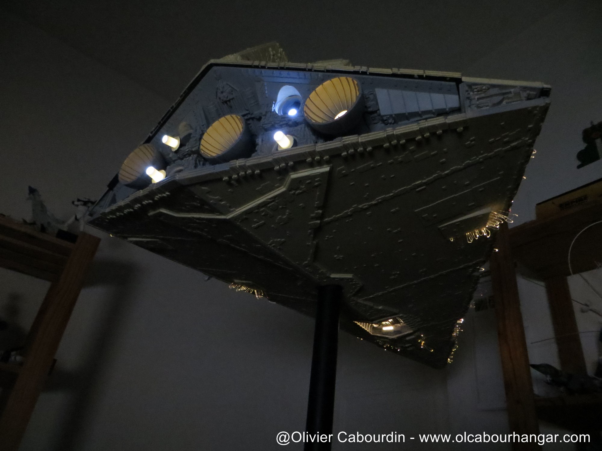
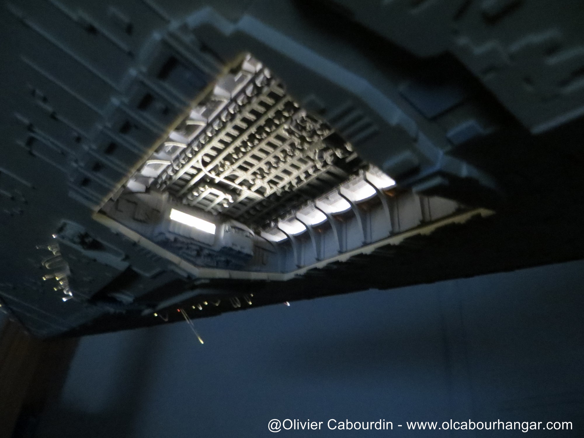
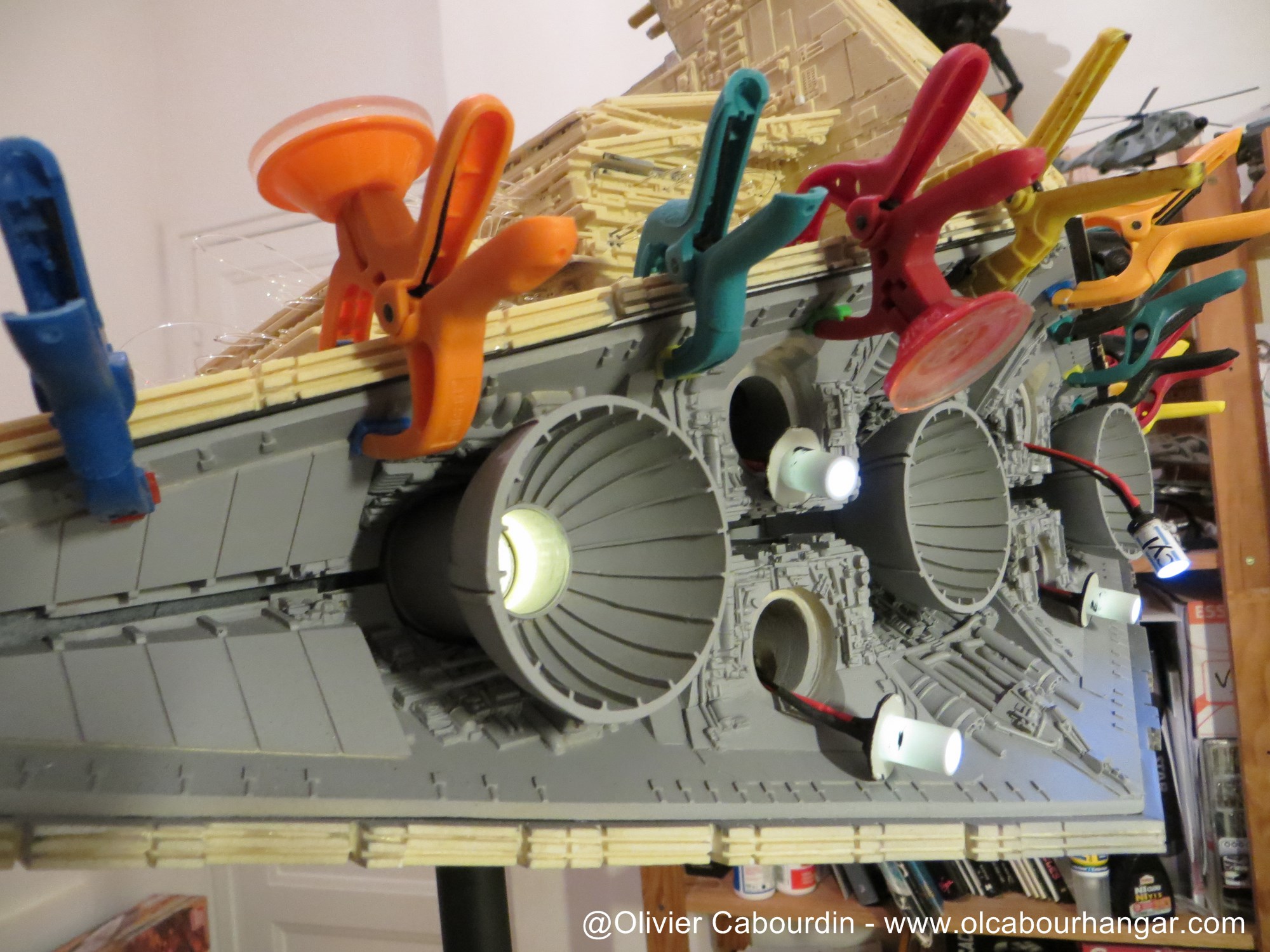
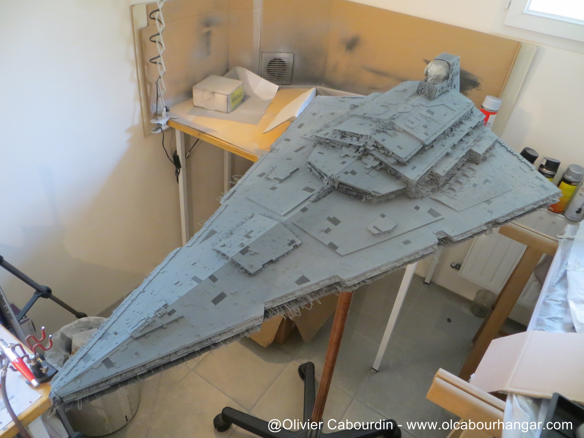
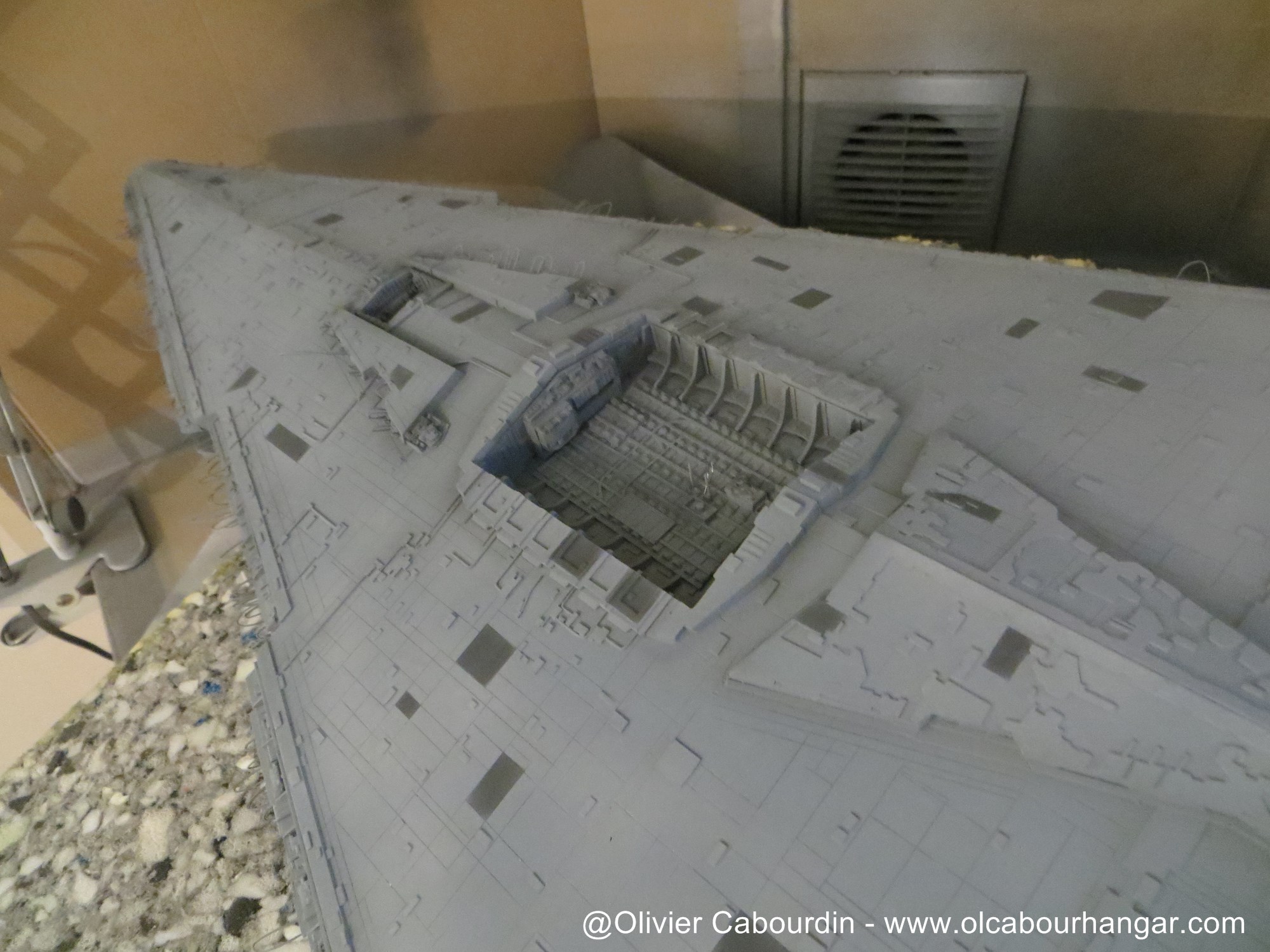
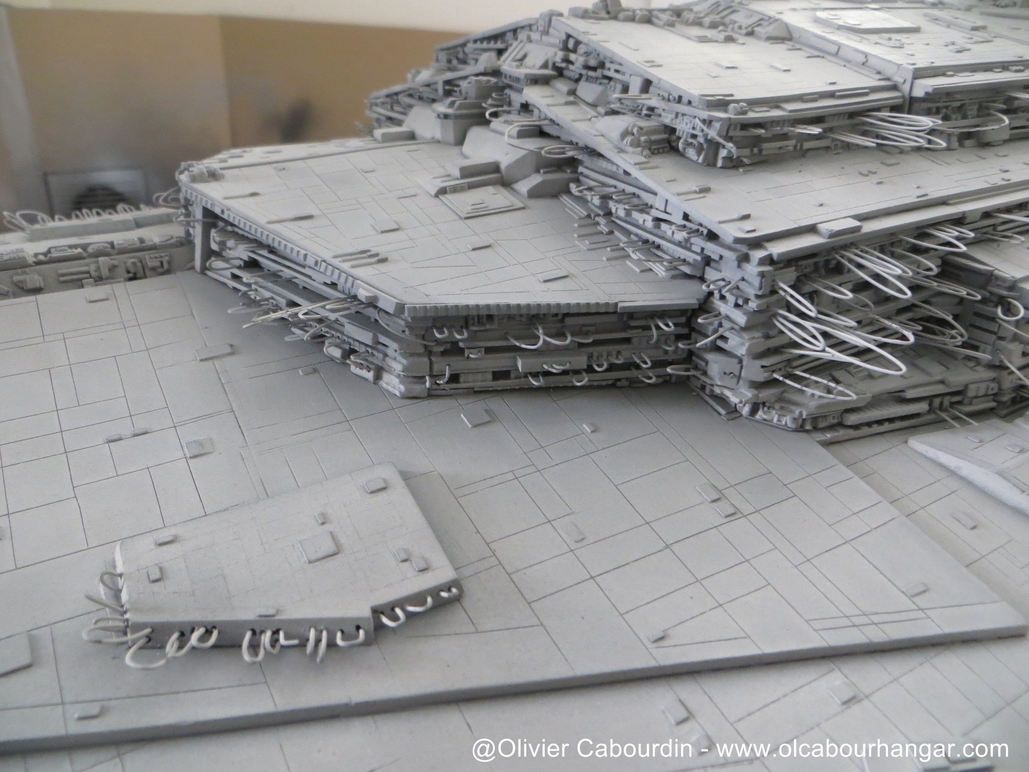
The underside support goes through the location of belly dome. The dome kit part was not glued, as I kept it to hide the hole when I will use the lateral support.
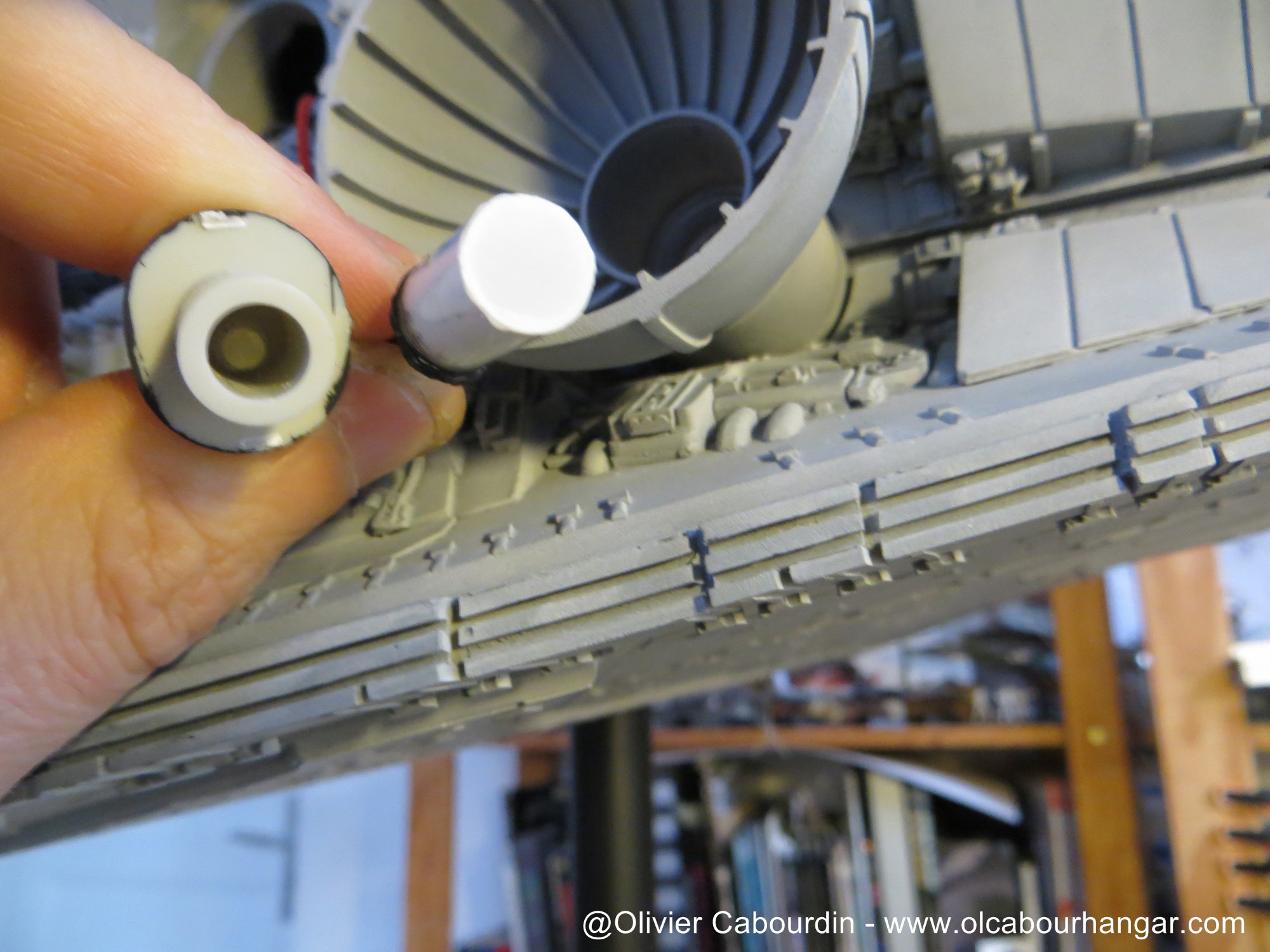
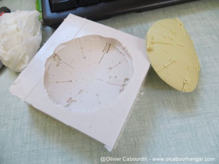
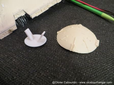
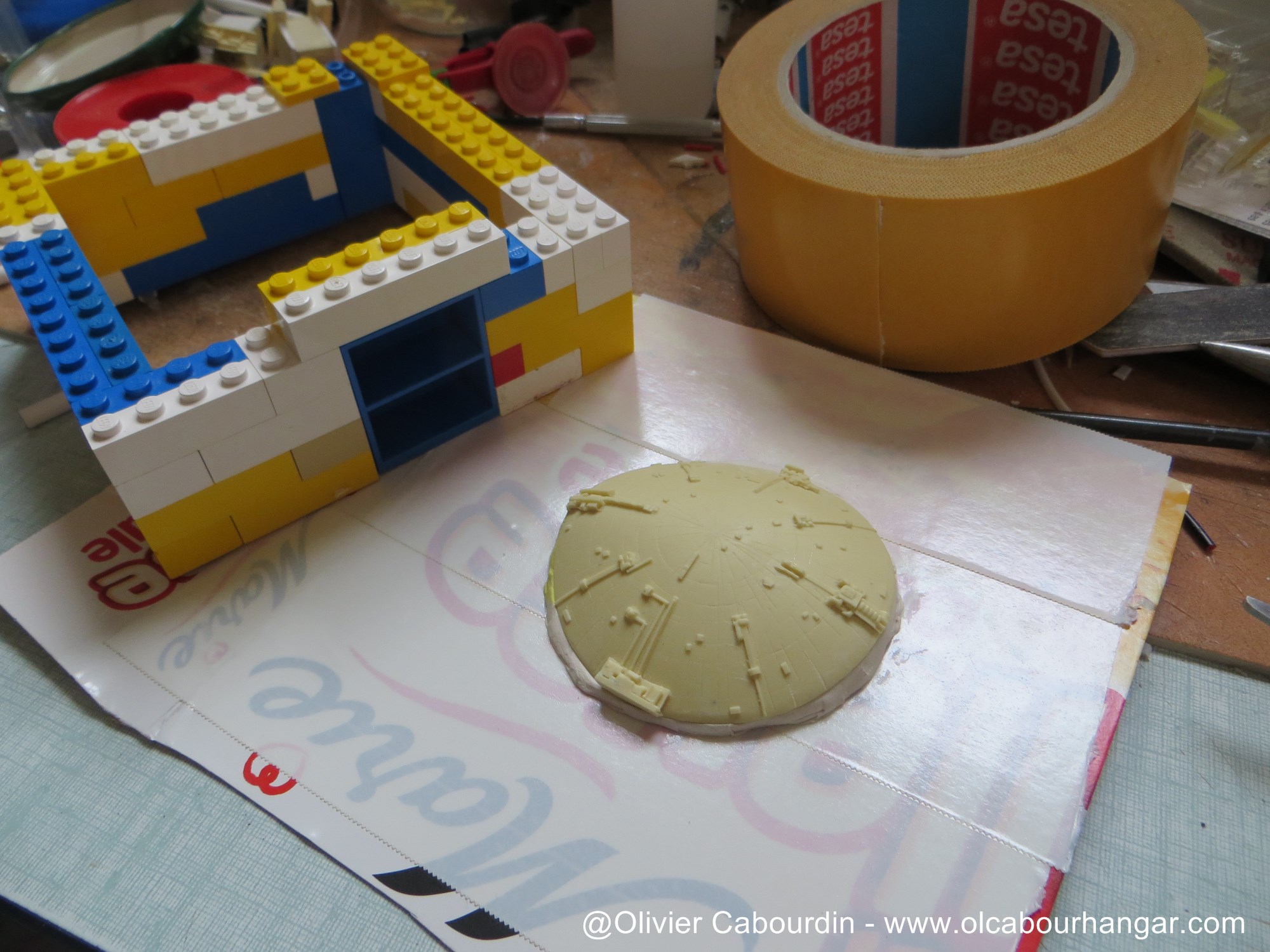
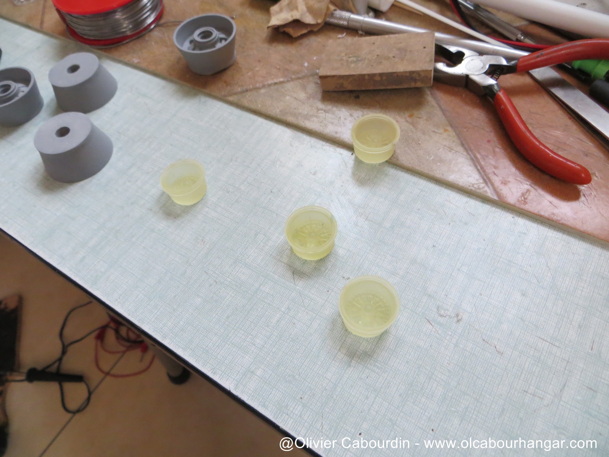
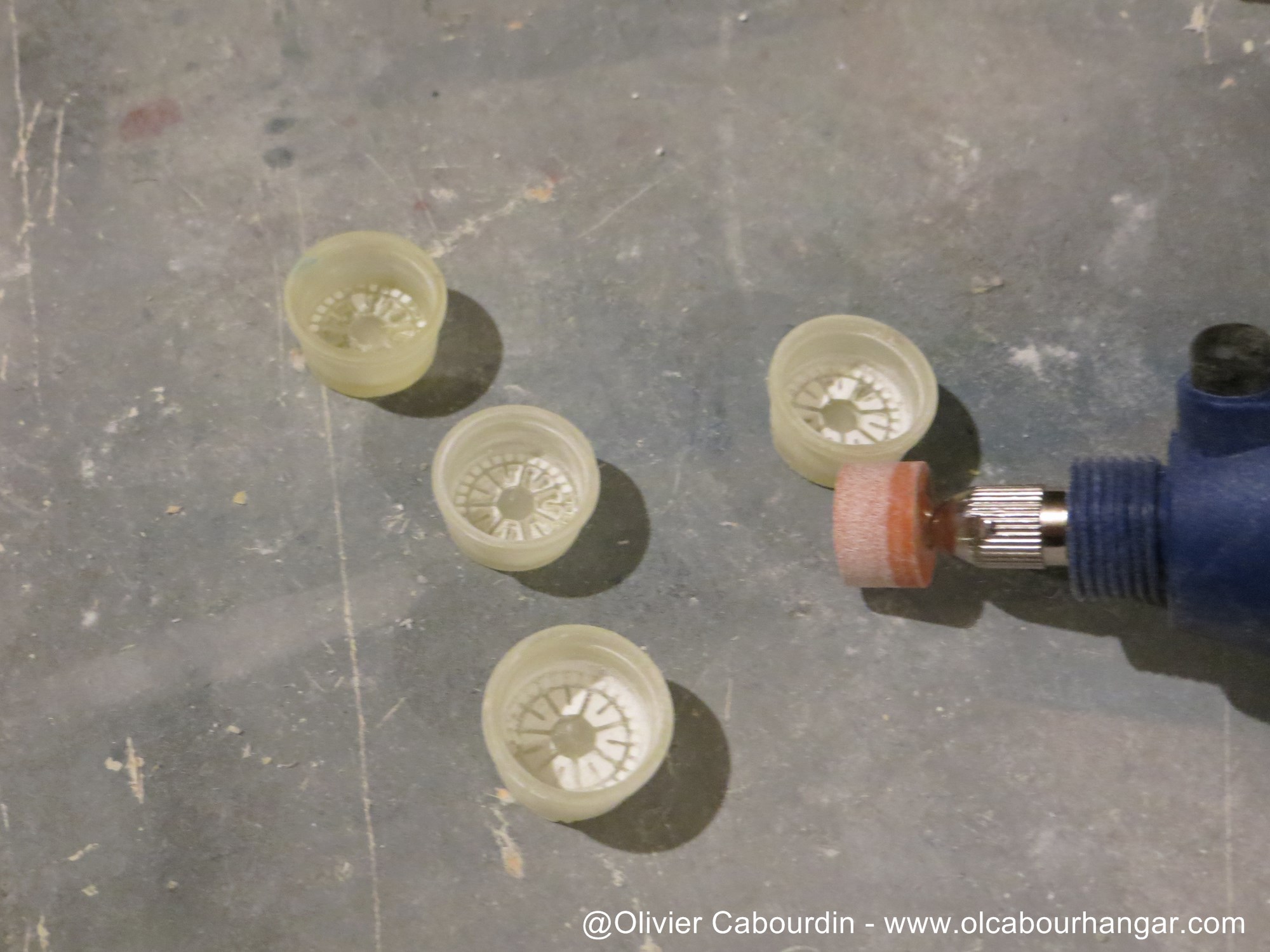
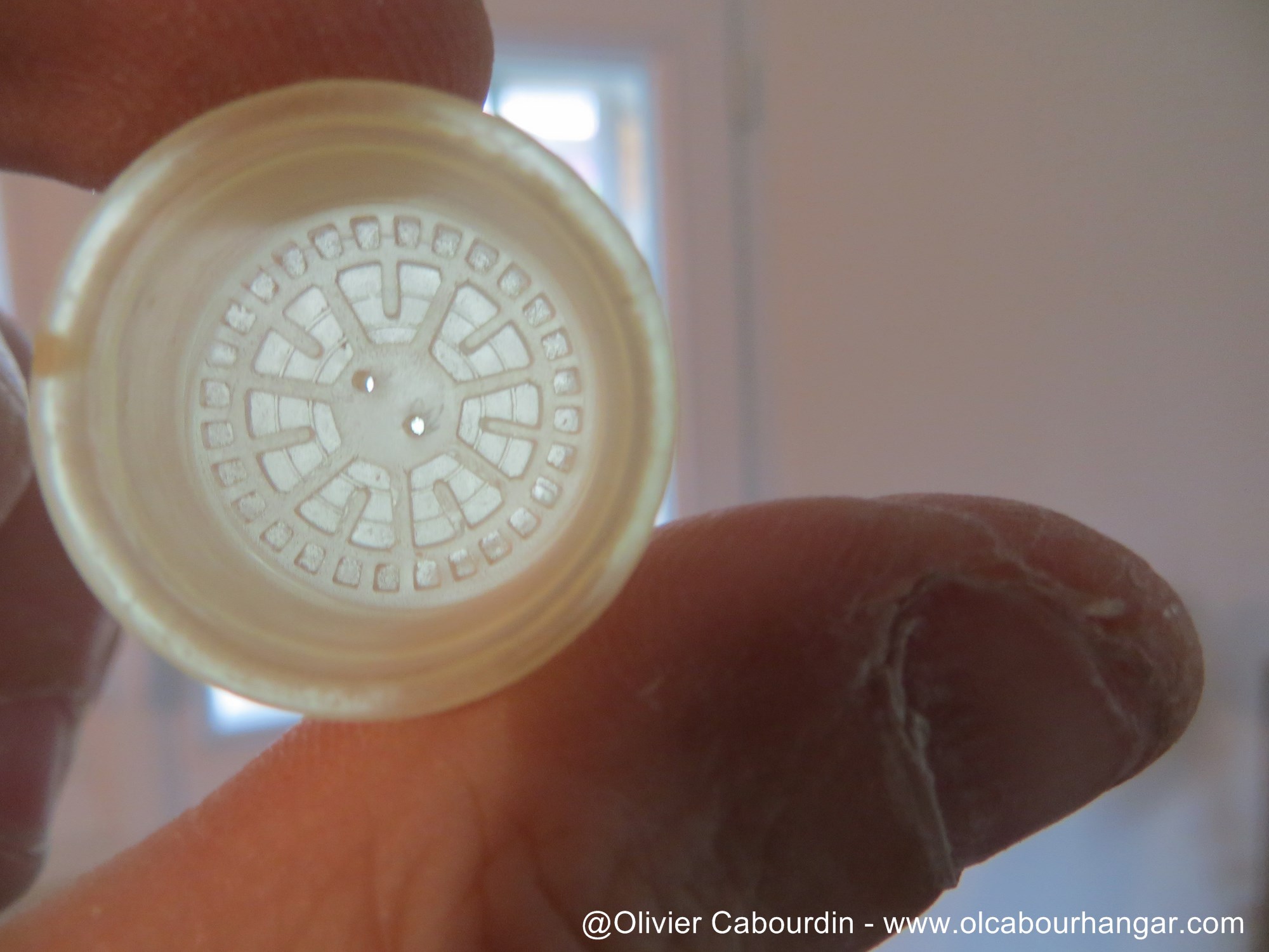
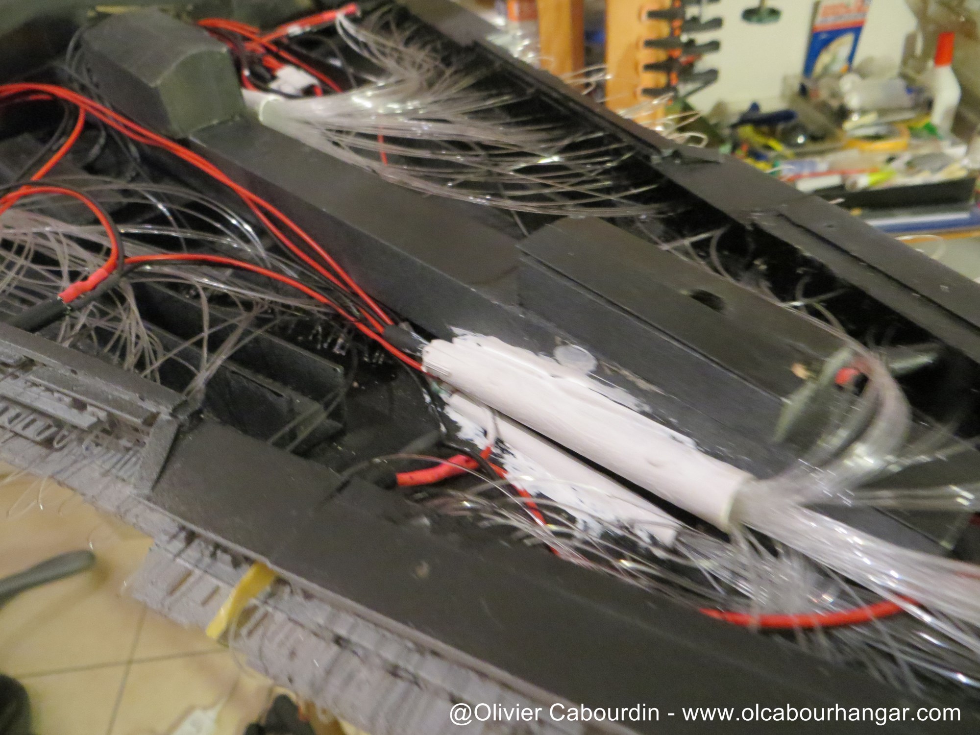
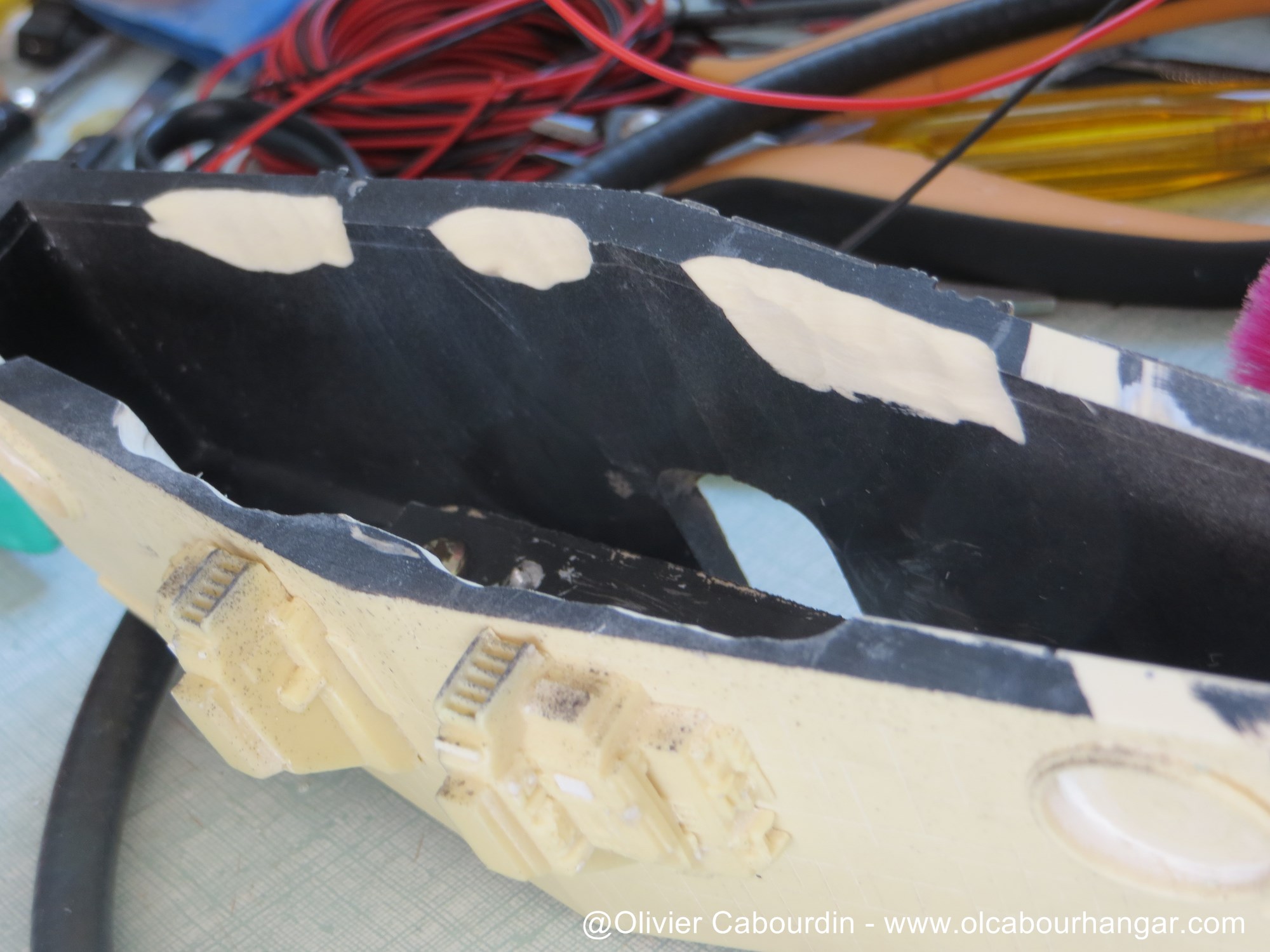
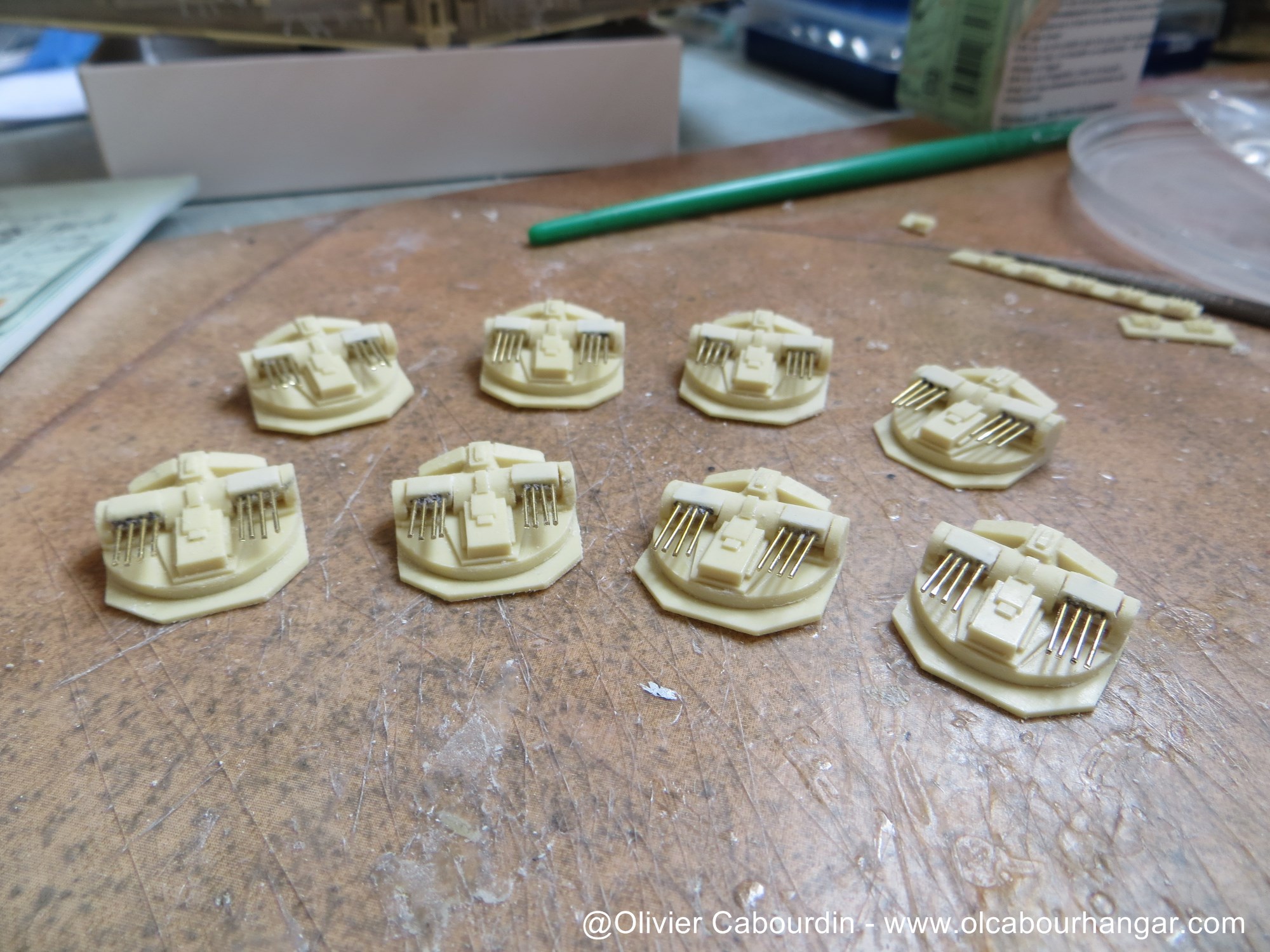
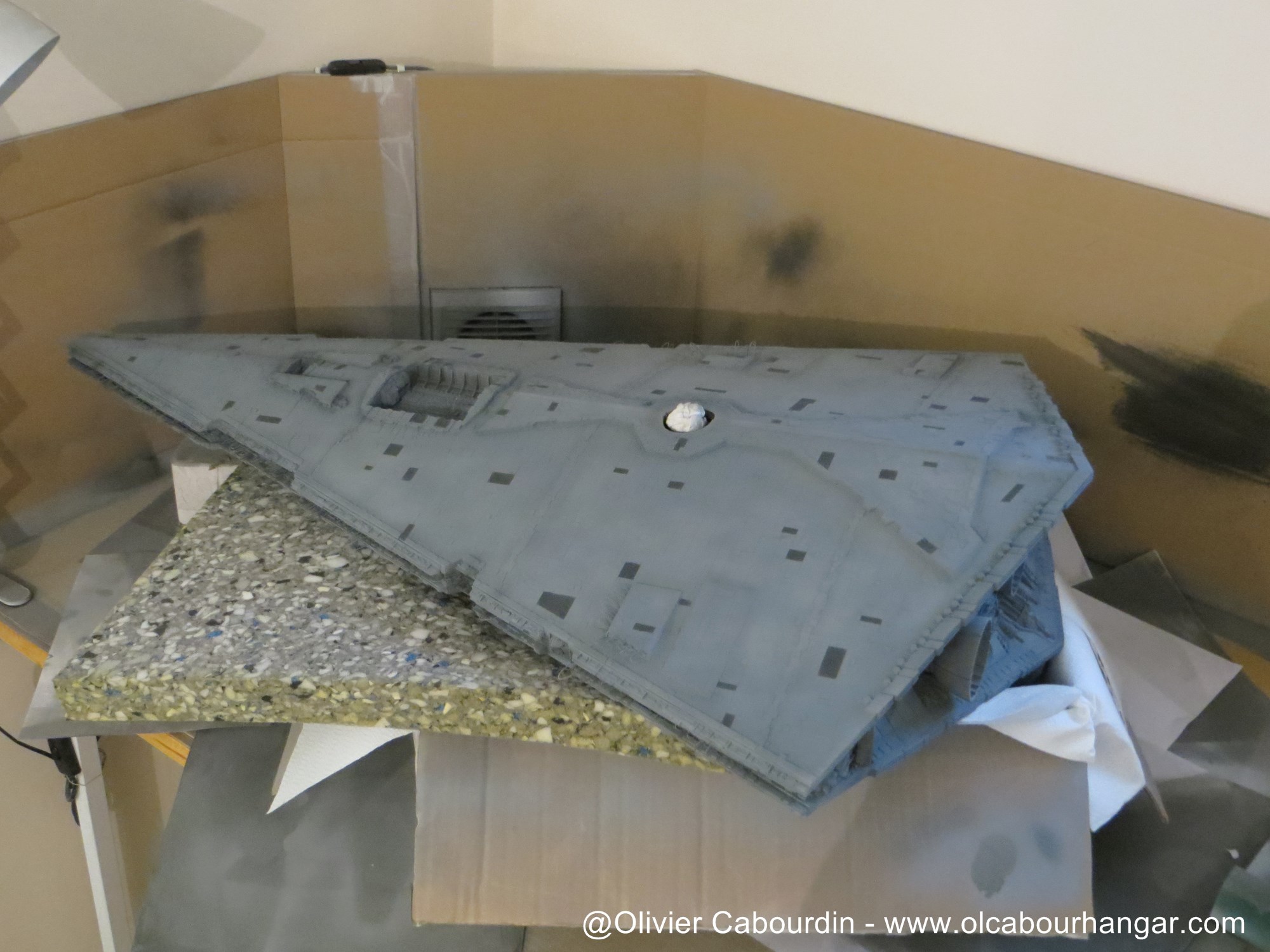
As the dome is an important visual element below the Stardestroyer, that bothered me to not have it. So I made a mold of the kit part, to have a copy which I hollowed out the center.


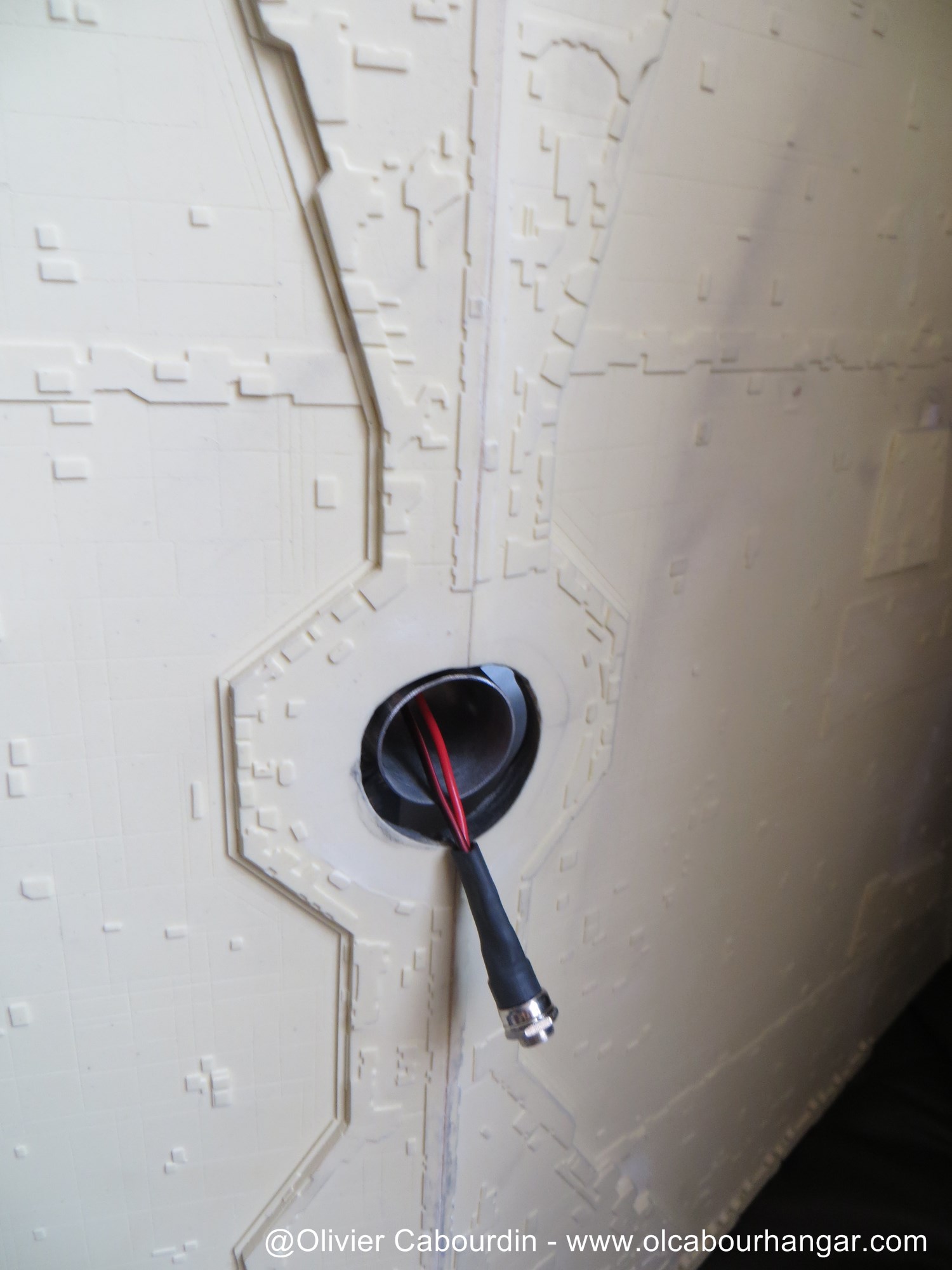
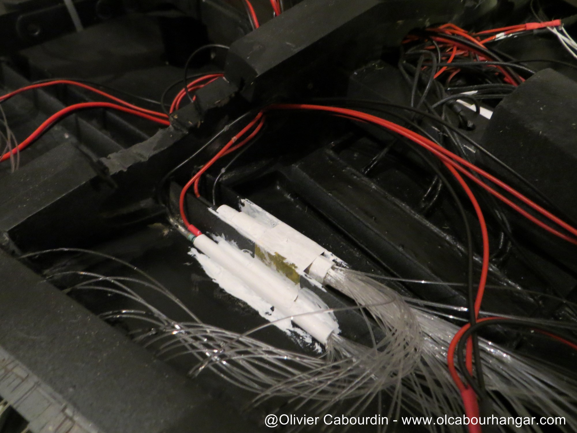
To fix these domes, I use two different methods :
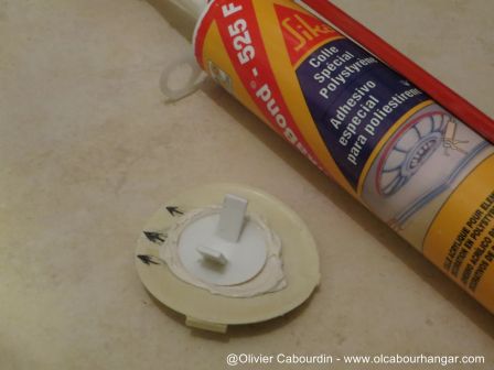
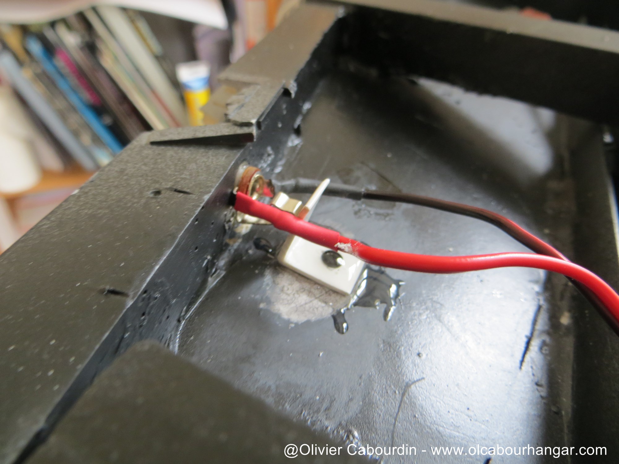
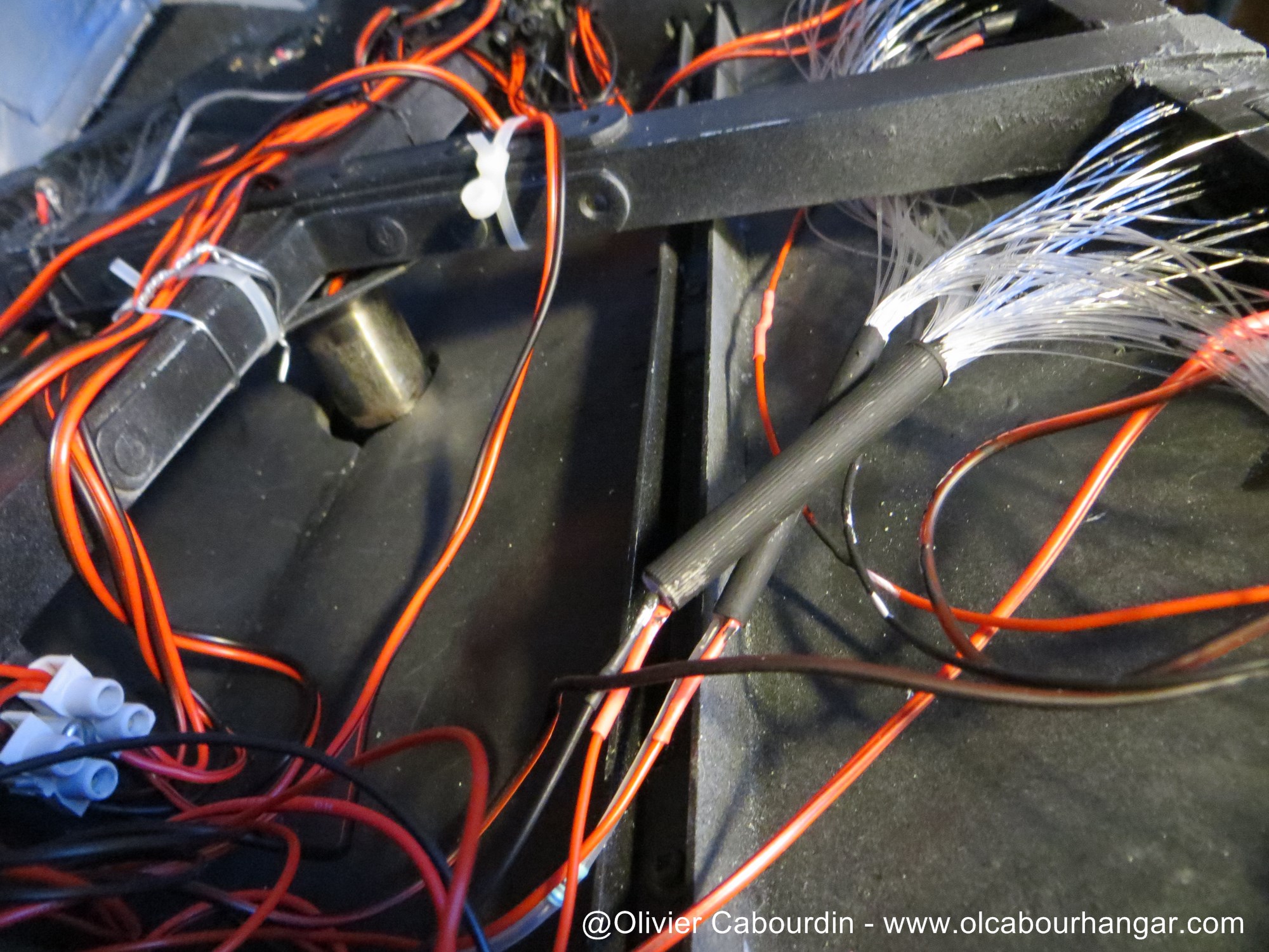
- the complete original dome is held with a water cistern blocking unit from a (new) toilet kit. It is glued to the dome.


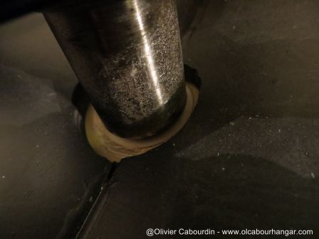
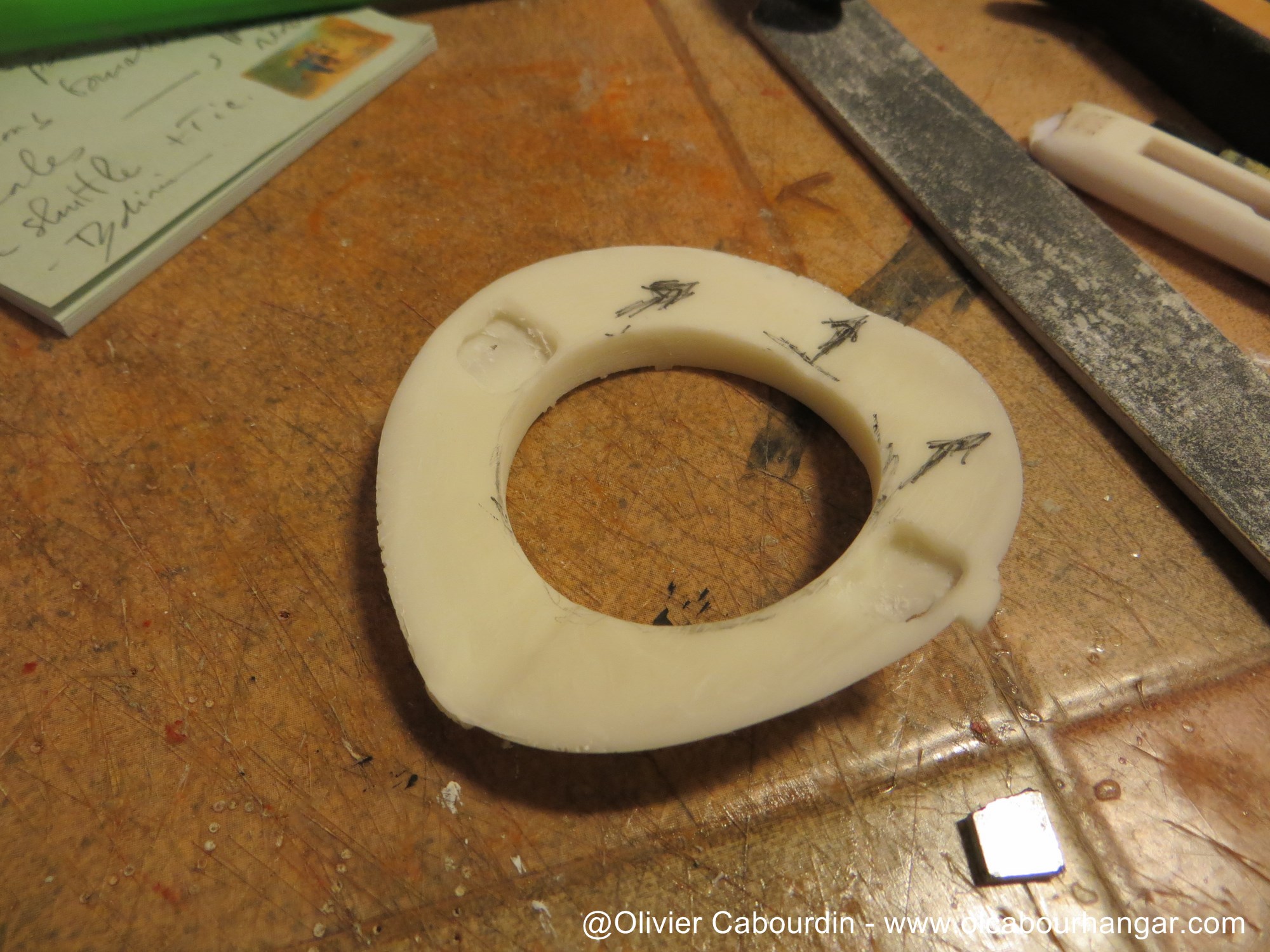
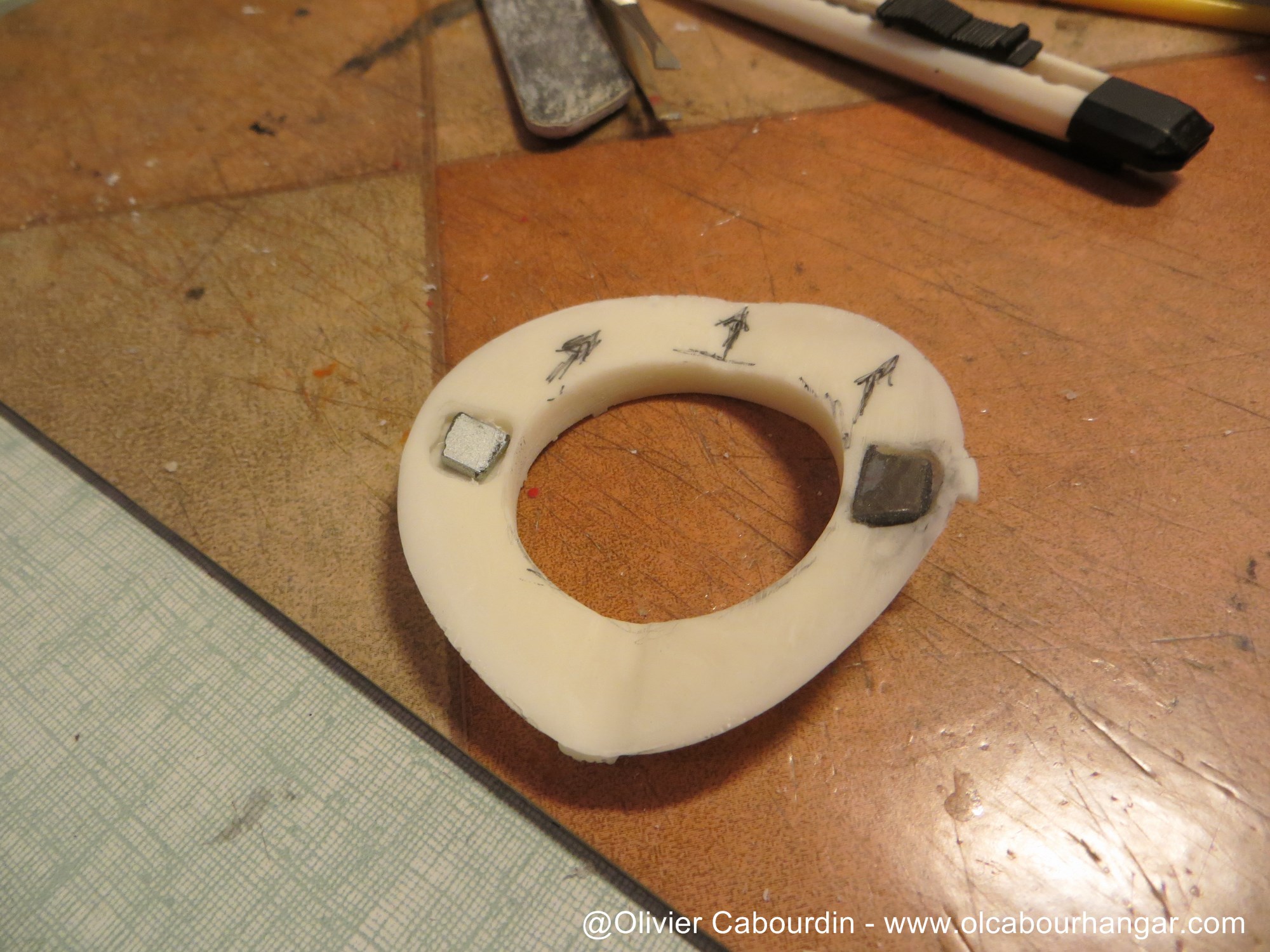
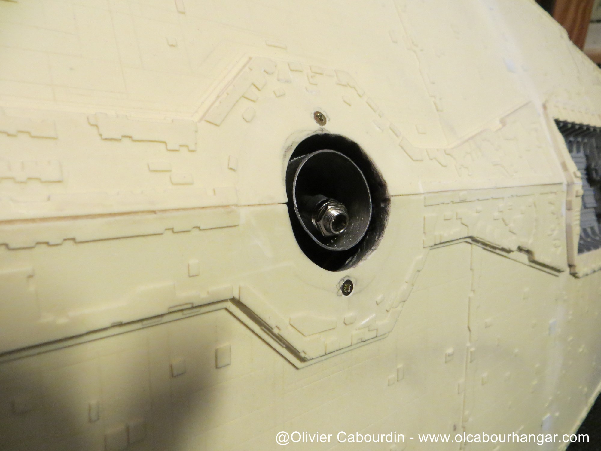
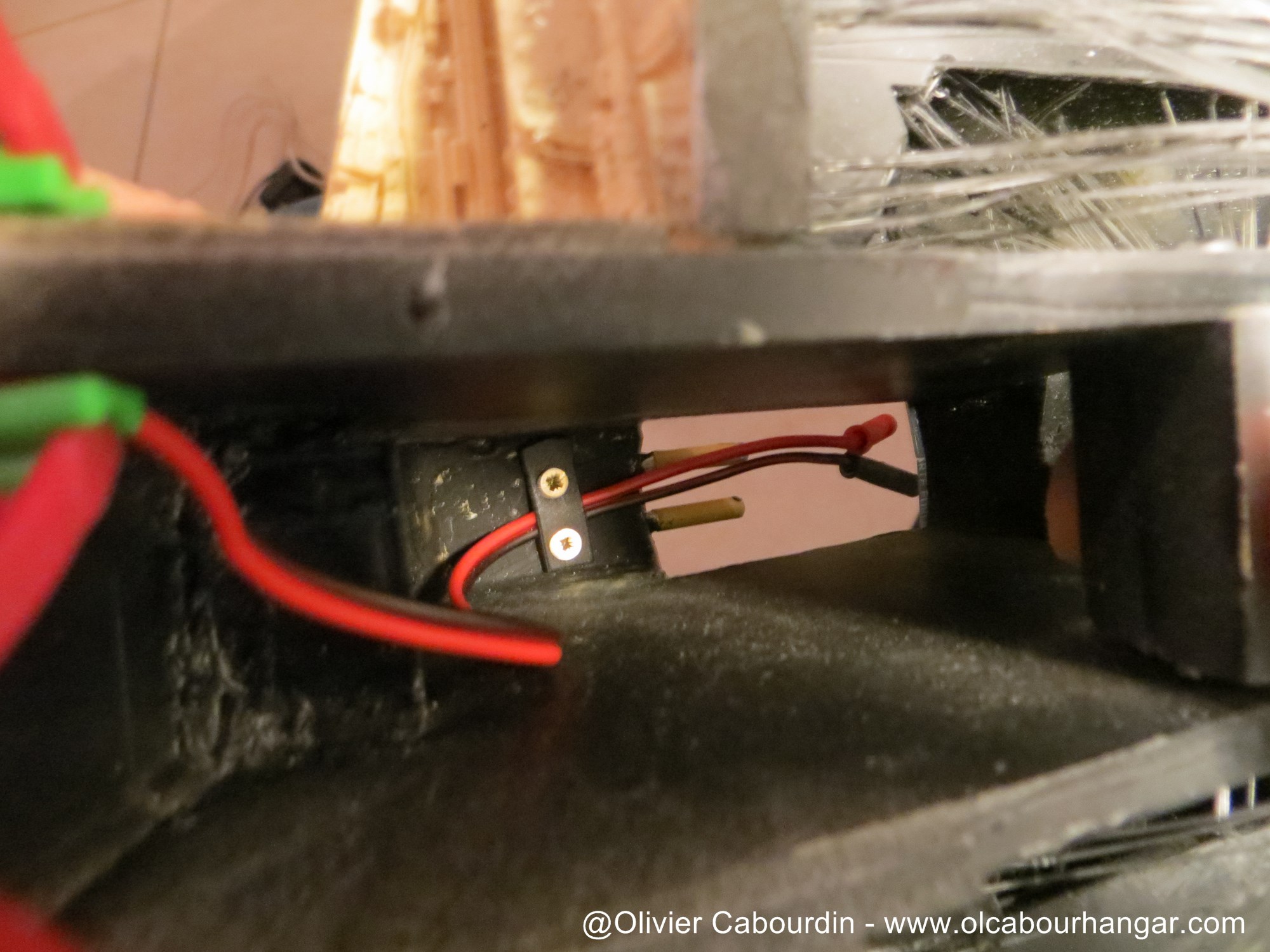
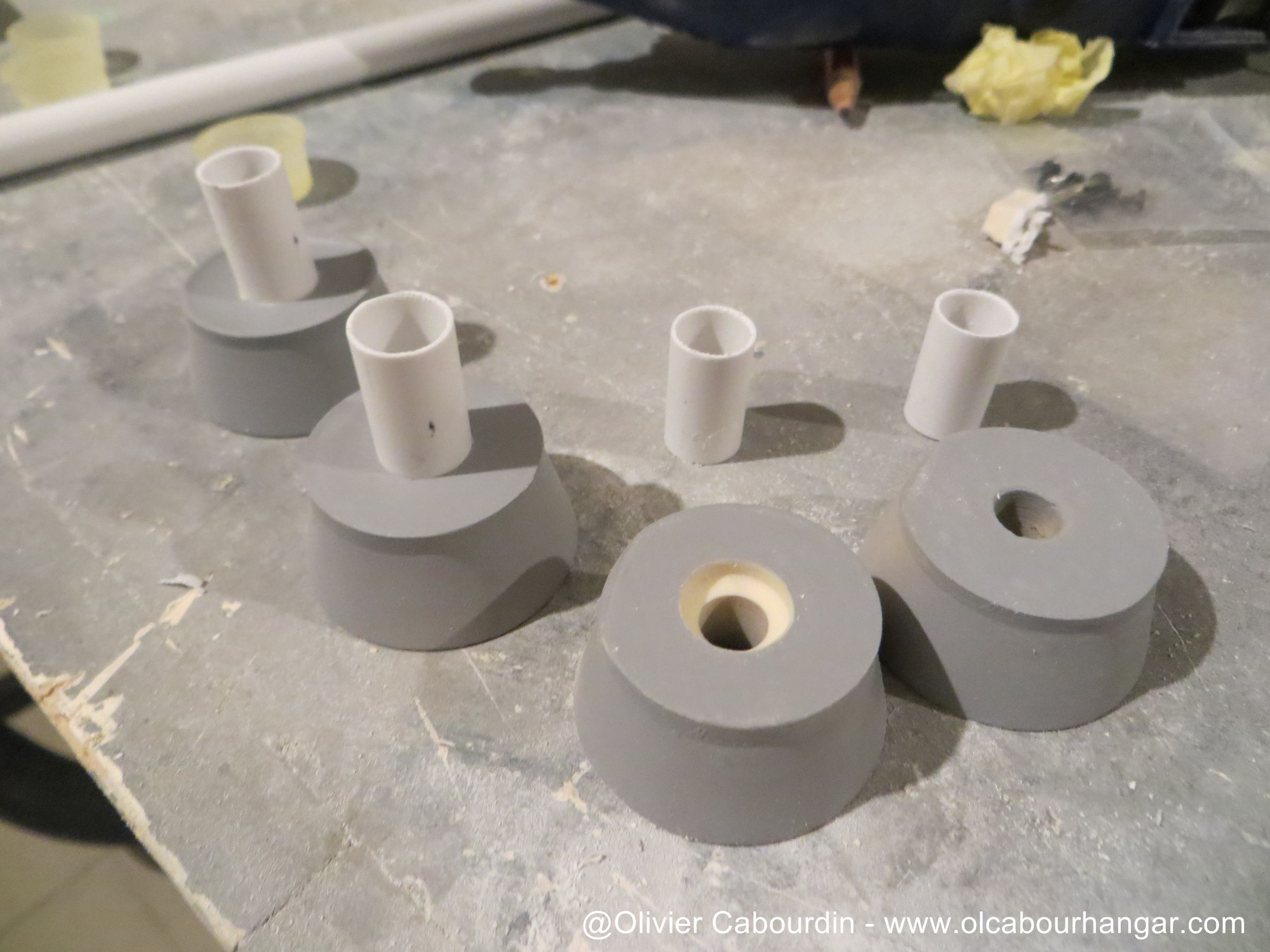
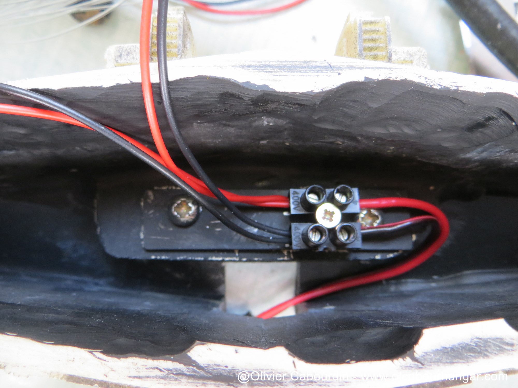
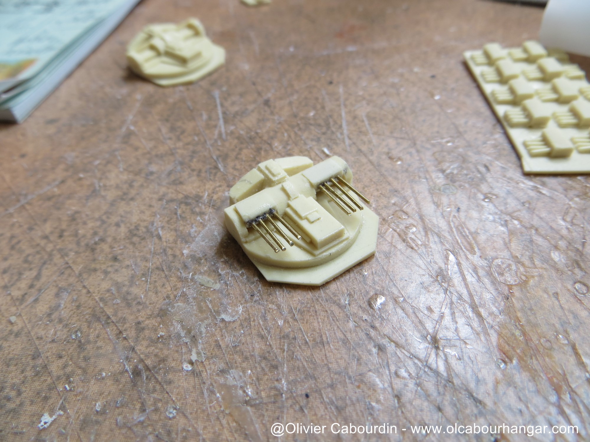
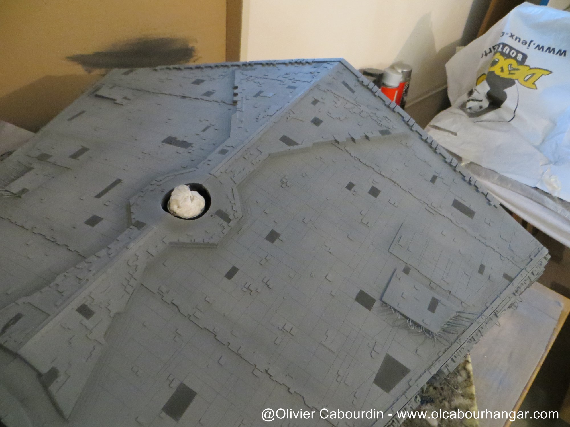
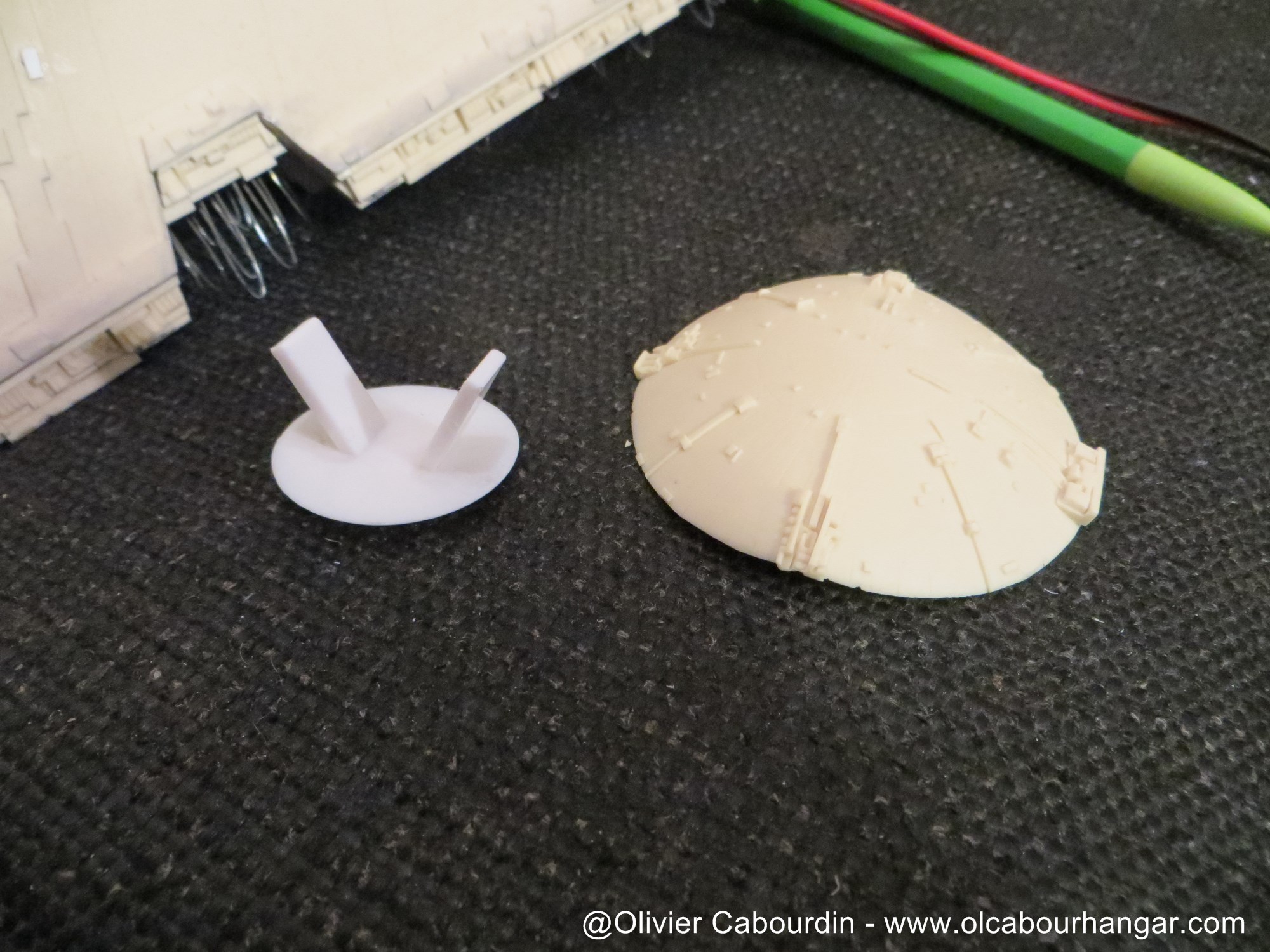
- For the hollowed dome, I first imagine a system of brackets but finally went with magnets : magnets in the dome, and screws in the stardestroyer belly.


Next is the setting up step of the electrical and lighting circuit.


Ventral Electric supply


Side electric supply


As the bridge is removable, connectors are done with plugs.


The 3 main thrusters are warm white LED, they are entrenched in truck covers (clear resin parts provided in the kit), painted black then aluminium.


The 4 secondary thrusters are cool white LED (they indeed have a bluish tint on the studio model). They are glued to bottom of tubes, themselves fit into the tubes glued on the engine bells, which will be fixed later.


On the set of model, some bulbs were exposed in the trenches, and lit comprehensive areas in the trenches. To avoid over-lighting the trenches, I use light rods (the bulb being so remote and hidden inside the model).
These light rods are made from frosted clear rods, tubes and warm white LED.
These 11 rods are then glued to the back of the trenches.
(unfortunately, no photo of the installation step)


As I am not sure of me with these light rods, so I placed a switch on the sub-circuit, hidden in the details of a side trench.
A second switch is placed on the sub-circuit of the engines, in case they would interfere during photo shots.


And I had to go with the optical fibers step (a really boring step)
They are folded in two, the loop staying on the outside (except for the bridge... no reason there... just forget this trick when I started it...). They remain well in place, do not escape and fill two holes simultaneously.


They are then set with a mixture of white glue and black paint.


The fibers are then grouped to warm white or red LED, inserted into tubes (evergreen or recycling of body pens or felt pens).
The white / red allocation is made like the original for the bridge, but randomly elsewher as it was too complicated to do, and besides the right side of the studio model was less detailed and included only very very few fibers (that was the left side that was filmed and then the image reversed).


The tubes LEDs are painted in white to enhance light diffusion inside.


then covered with black for light leaks to the outside.


For the bridge, I had to make some adjustments.


First tests.


It is time to finally close the box, so the whole upper part is installed, glued and screwed to the bottom part.
The back requires a bit more attention (cyano glue and putty) to prevent light leakage.


Last adjustments before painting:
- Realization of covers of the light rods (otherwise too bright)

- side connectors covers (tubes and tank wheels)


- the canons of turbolaser turrets are awfull as is and are replaced by a simple brass rods


- the turrets locations need wedge so that they are level horizontally.

Before:


After:


- the screws are hidden behind small squares of plastic card.


- Obviously, it was just cured when I realize I forgot fiber on a belly outgrowth ! Too bad, the holes are filled with plastic putty. Grrr!

 
This is simply magnificent!

As a complete new person to the model building world I am curious to how
you will paint the ship and not paint over the optic fibers?
 
The openings are masked and then a coat of primer is applied


The preshading consists of panels randomly painted in Panzer gray all over the entire surface.


It is then covered with an off white (white with few drops of sky grey xf19)


Even if the original model is even whiter than what I did, I think it is too much white.
So, to mitigate it, I sanded the surface with an abrasive sponge.


After a light gray oil wash, I airbrushed very thin coat of the same light gray to finally arrive slowly to the color that satisfied me.


As a complete new person to the model building world I am curious to how you will paint the ship and not paint over the optic fibers?

All the fiber optics will be painted over with the rest of the ship and since the fiber optics are threaded with loops far beyond the surface of the ship they can be cut afterwards so they become clear again. See the last 3 posted pictures :)

Chaim
 
This is simply magnificent!

As a complete new person to the model building world I am curious to how
you will paint the ship and not paint over the optic fibers?

Thanks Datfly
Sorry, I missed your question when posting.
Sym-cha explained perfectly: all the fiber optic are set to rise a bit from the surface, painted as is, then cut with pliers along the surface. Where you cut, the FO is then clear for the light

All the fiber optics will be painted over with the rest of the ship and since the fiber optics are threaded with loops far beyond the surface of the ship they can be cut afterwards so they become clear again. See the last 3 posted pictures :)

Chaim

Thanks Chaim
:eek:eek Majestic :thumbsup

Thanks sqbiedo :)
 
Need updates.

I was gonna pass on the RC Star Destroyer due to the amount of work it required after wanting it for years. Then I saw this built and it was what I had in mind for how I wanted to do mine and I decided screw it,...and took the plunge. Should be here in a week so, so all the pain and work I am going to go through it totally your fault.:lol

Tom
 
Back on this wip after a very long absence.

While the paint was drying, I go into a small scratch Shuttle Tydirium around a blue 2mm micro LED. I reduced 3-view blueprint for a length of 1.2 cm. The metal rods welded on the LED are embedded in the upper wing. They bring electricity from the connector hidden in the hangar bay.


The 2 escort Tie are only 4 mm long.
The wings are plastic card, the rest is cross of brass rod welded and some white glue to the central ball.

 
- With the paint now fully dryed, the optical fibers are cut

- The light rods covers are then placed

Before


After


- the engine lights are too powerful, so I added tracing paper round on blue engines.


For 3 large engines, tracing paper did not work (the aperture is too large and the result too flat). So, I placed cyano plugs directly on the LEDs. They are held with white glue.


left: after | right: before


- A carrying case is custom built, with 10mm plywood and insulating foam panels.


This thread is more than 7 years old.

Your message may be considered spam for the following reasons:

  1. This thread hasn't been active in some time. A new post in this thread might not contribute constructively to this discussion after so long.
If you wish to reply despite these issues, check the box below before replying.
Be aware that malicious compliance may result in more severe penalties.
Back
Top